
Abstract
Significant temperature rise is stimulated during high-speed machining of metals, specifically in dry cutting conditions. This experimental investigation undertakes the effects of uncoated, single layer coatings (TiN and TiAlN), and multilayer coatings [TiAlN/TiN (9 + 5 µm), (9 + 3 µm), (9 + 1 µm), and (5 + 1 µm)] on cutting tool material during dry orthogonal cutting of AISI/SAE 4140 alloy steel. The study compares crucial parameters such as cutting and feed forces, chip-tool contact area, thickness of deformed chip, chip reduction coefficient, heat partition ratio, flank wear, and shear angle. The layer TiAlN used as the first layer from the Tungsten Carbide (WC) substrate owing to its better adhesion property, whereas TiN used as the second layer (top coating) owing to its better sliding behavior. In this research, cutting operations have carried out using Dean Smith and Grace Lathe machine. A Scanning Electron Microscope (SEM) also used along with a Kistler 9263 dynamometer to measure cutting forces. The cutting temperatures are measured with the help of an infrared, high-resolution thermal imaging camera, ThermaCAM model SC3000 by FLIR. Results have shown that layers act as a thermal barrier that block excessive heat generation in the cutting tool. Thus, this increasing the surface finish, tool life, and overall efficiency, while reducing the abrasive wear, tear, and parallel ridges due to rubbing friction. Furthermore, it has found that multilayer coating of (9 + 5 = 14 µm) shown good consistent results with less variance, specifically in the high-speed machining regions. Hence, the study evidently justifies the usage of coated tool inserts in high-speed dry cutting operations.
Keywords
Introduction
Chip formation is an imminent process during metal cutting that greatly affects tool wear, tool life, surface roughness, and surface finish and. It is the process to remove metal layer by a cutting tool, which is termed as the chip. Metal cutting operations are very common among many heavy industries like manufacturing, construction, aerospace, automotive, etc. to carry out most of the manufacturing activities in the plants. In the context of engineering, the word machining mainly describes a metal removal process. Turning operations have utilized for metal cutting due to its wide usage in myriad manufacturing industries. During the process of metal cutting, two major operations take place: mechanical and thermal. The former includes the removal of excessive or unwanted metal from the workpiece, whereas the latter includes heat generation during machining operation. The cause of heat generation is the frictional interaction between the workpiece material and the chip, which leads to increasing tool temperatures and plastic deformation within the materials.
The study of chip morphology has been into consideration since many years and many authors have worked to further study the topic into extreme detail to determine the chip behavior during the process of metal cutting. In a study, Holleck et al. 1 analyzed multilayer coatings of material TiC/TiB2 in a process of magnetron sputtering during decomposition of numerous ion bombardments. Munemasa and Kumakiri 2 worked on preparing SK5(JIS), which is a carbon tool steel material. This tool is specifically for substrates that are finished to numerous surface roughness, ranging between (Rmax) values of 0.2–17 µm. They deposited TiN and Titanium on their prepared substrates using the method of magnetron sputtering. On the other hand, Knotek et al. 3 worked on identifying various mechanisms that were helpful in improving material coating properties.
In a study by Halvarsson et al., 4 they worked on preparing cutting tool inserts that were made of cemented carbide. These inserts were coated with alumina whose cross-section was made of thin foils. Löffler 5 took a systematic approach to develop new and more useful Physical Vapor Deposition (PVD) tools. His worked was tested and proved success in numerous applications. Yurgartis et al. 6 worked on measuring possible descriptions of numerous crack coatings like types of cracks, their width, orientation, area of cell, and gaps amidst them. Ma et al. 7 utilized the method of hardness indentation along with scratch tests on a fractured cross-sectional piece of specimen. They worked on coatings that were hard to analyze the behavior as to how fractures and deformations occur using a Scanning Electron Microscope.
Knotek et al. 8 worked on coated cutting tools to determining their performance characteristics. They took a different yet innovative approach by measuring the substrate quality, structure, and composition of material coatings. On the other hand, Leyendecker et al. 9 performed their research on the combined modern PVDs. They chose two hard coatings, namely Al2O3 and TiAIN, while selecting a system of new multilayer that were deposited at a temperature lower than 450°C. This showed enhanced thermal stability relative to the previous PVD coated materials. Selinder et al. 10 focused their research on the evaluation of carbide cutting tools, namely that were primarily TiN/NbN and TiN/TaN. These cemented carbide tools were super lattice made with lamellae thin films. The machining tests were performed in milling machine where results indicated extraordinary performance relative to single layer coated tools such as CVD or PVD.
In an investigation by Su et al. 11 to measure the performance of fatigue and tension for 1045 AISI steel material. They carried out tests for both coated and non-coated steel. Their findings concluded that applying thin surface films on the material did not have any impact on material tensile strength. Kang et al. 12 performed experimentation on reactive sputtering process where they found that TaN films were deposited at a ratio of 0.4 with N2/Ar showed high crystallinity along with high adhesion strength and material hardness for the multilayer Ta/TaN. In a hard machining experiment by Barry and Byrne,13,14 they worked on the acoustic emission signal energy. Their results showed that, in comparison to the machining of relatively softer material such as pearlitic steel, the acoustic energy of harder material could be around twice in the magnitude orders.
Cutting conditions can improve the stability of the cutting process. 15 M’Saoubi et al. 16 used this analogy and researched on a technique which was primarily based on the infrared CCD camera that helped analyze the tool’s cutting edge temperature distribution. In an experimental analysis by Venugopal et al. 17 during the machining operation of Ti-5Al-5Mo-2Sn-V under cryogenic dry cutting conditions, it was found that Ti alloys did not go under suitable machining operation when cut with TiB2. On the other hand, Abukhshim et al. 18 performed turning tests of EN-19 steel alloy at varying cutting speeds, ranging between 200 and 1200 m/min while keeping the constant depth of cut of 0.1 mm. Subsequently, during the process of oblique cutting, Moufki et al. 19 inferred that friction condition at the chip-tool interface was greatly affected owing to the dissipation of heat because of the larger sliding velocity and pressure values.
In the quest to analyze the effects on the frequency of chip morphology due to the varying cutting speed values, Belhadi et al. 20 found a direct relationship of chip segmentation frequency with the cutting speed and inverse relationship with the feed rate. Therefore, increasing the cutting speed increased the frequency whereas the frequency decreased as the feed rate was increased. Mativenga et al. 21 claimed that tool coatings also played a vital role and influenced the area of contact and the associated heat fluxed during the metal cutting operation. Bigerelle et al. 22 worked on estimating the suitable roughness parameter and asserted that those that did not include extreme values. Additionally, at 20 m/s of cutting speed, the temperature fields for C15 and 42CrMo4 materials showed maximum temperatures of 630°C and 870°C, respectively at the interface of chip and tool. 23 According to finite element modeling by Iqbal et al. 24 to analyze rubbing process, coefficient of interfacing heat transfer was observed to be decreasing at slow rubbing speeds; however, as the rubbing speed was increased to high values, the heat transfer coefficient became approximately constant.
Coated materials have more rigidity against wear and tear than their counter parts, as investigated by Lee et al. 25 to analyze how the surface temperature of drills. During finite element modeling and simulations of Al6061-T6 to observe the process of micro-milling, Wang et al. 26 utilized two models, namely Merchant and Arcona-Dow models, and found that variation in length of the shear band and the chip-tool contact length were the major causes that produced segmented chips. In a study of turning operation of nickel-based Hastelloy C-276 by Khidhir and Mohamed 27 to predict the wear types, the burr size of the chip for uncoated inserts was found to be more than that of the coated inserts. In fact, the burr size almost vanished for coated tips at speeds higher than 150 m/min. Liew 28 presented a research that showed that spraying minute amount of mineral oil, even in the form of mist helped reduce the wear and tear and signs of early abrasion, and also decreased the premature formation of chipping, delamination, and cracks. Bermingham et al. 29 worked on constant speed turning process in the presence of cryogenic cooling and changed depth of cut and feed rates at different varying combinations. They asserted that tool life improved six times with lower depth of cut and higher feed rate. The same way, Gill et al. 30 also researched to analyze the strength of adhesion phenomenon during orthogonal turning of tungsten carbide cutting inserts which were treated cryogenically.
Fernández-Abia et al. 31 studied the behavioral differences of AISI 303 stainless steel material under high-speed cutting operation. Their study concluded that cutting conditions became favorable as the speed rose to 450 m/min or higher. Furthermore, they found that the thickness of chip was also reduced at speed over 450 m/min, benefitting the tool life and life expectancy. Fernández-Abia et al. 32 worked on understanding the effects of different co-efficient of forces to predict the behavior of AISI 303 stainless steel during turning operation. Numerous tests were performed at high values of cutting speeds (from 350 to 750 m/min) using the mechanistic technique. Their model predicted an error margin on around 8%, given that the tool geometry was kept the same. Pereira et al. 33 researched the eco-efficiency of AISI 304 stainless steel using a combined technique of Minimum Quantity Lubrication and cryogenic cooling during turning operation. Their results revealed that this duo technology could improve the tool life up to 50% and feasibility to carry out machining operations at speeds of around 30% larger than that of dry machining operation, along with sustainability of the environment. In a study to analyze the sustainability of different lubricants, Pereira et al. 34 utilized five different natural oils, such as oleic, sunflower, ECO-350 oils, to replace the commonly used canola oil during high-speed cutting of Inconel 718. This proved not only environment-friendly cutting operation, but also helped improve the tool life up to 15%.
Polvorosa et al. 35 compared the effects of different coolant pressures during face-turn testing of Wasp alloy and Inconel 718, which are the common alloys for aero-engine applications. They found that structures with bigger grain sizes led to a greater notch wear, whereas a greater flank wear was noticed with structures of lesser grain size. In another environment-friendly approach of cryogenic and minimum quantity lubrication (MQL), a nozzle-adaptor spraying methodology was used by Pereira et al. 36 to perform smooth gas machining operation of Inconel 718. The theoretical-based analysis was matched with CFD simulations as well as practical scenarios to identify the differences, which predicted increased tool life of up to 93.5%. During machining of Inconel 718, Díaz-Álvarez et al. 37 used a numerical prediction technique to measure high temperatures using a dual-colored, fiber-optic-based pyrometer. Their temperature sensor was powerful enough to work in the range of 250°C–1200°C . They found that flow of heat toward the workpiece in the primary zone was around 17%. However, the effect was found to reach severity as the feed rate was varied to a smaller value of 0.05 mm. Pereira et al. 38 also studied the feasibility of friction drilling to analyze the effects on the performance and life cycle changes during wet and dry drilling of dual-phase steel material. Their technical analysis showed a better surface quality in friction drilling rather than the conventional techniques. Thus, stressing on the need to improve traditional use with the improved counterparts.
Pereira et al. 39 studied a thermal resistant material, Inconel 718, during high-speed milling under CO2 showered cryogenic conditions. They used CryoMQL external lubrication to compare it with conventional lubricated cooling practice. The outcome showed that with CryoMQL, the tool life could be improved by 57% in comparison to the technique of emulsion coolant. Rodriguez et al. 40 used a cryogenic cooling technique while drilling stacks of CFRP-Ti6Al4V. Instead of working on a dry drilling operation, they switched to fluid drilling wherein they used liquefied CO2 to shower on the material being drilled. Their results highlighted reduction in tool-tip temperature and less damage in edges of tool, increasing the tool life. In the life cycle analysis during machining of Ti-6Al-4V Titanium Bar, Khanna et al. 41 assessed the environmental effects and tool life with the use of conventional cutting fluids. They utilized liquid carbon dioxide and observed low hazardous impacts on the environment and tool life, stating that the conventional cooling method served to reduce around 75% of the overall tool life when worked at high speed machining. Gómez-Escudero et al. 42 undertook a study to perform milling operation for the manufacturing of knee prostheses joints. They also utilized CO2 cooling method on a Ti-6Al-4V knee implant. They asserted that with this cryogenic cooling method, they obtained high surface finish and less roughness in the manufacturing joints.
Pérez-Ruiz et al. 43 studied the impact of force of cutting and features of anisotropy on Inconel 718 during the milling operation. They observed that cutting forces decreased while fabricating a low volumetric energy density (i.e., grain size less than 10 µm), given that the axes of grain and tool were kept parallel. González et al. 44 used CryoMQL method for Ti6Al4V integral blade rotors during flank milling operation. They used technique to eliminate the conventional oil emulsion method, which is very commonly used as a coolant during high speed cutting. Their results revealed that usage of CryoMQL prevented formation of dry ice and nozzle-pipe clogging. With environment preservation in view, Pereira et al. 45 performed CFD simulations on cutting tools made of super alloys using cryo-cooling technique to compare the differences with commonly used oil emulsions operations. Their results proved improvement in the milling operation, reduction in tool temperature, and cutting forces of around 40% and 25% respectively, and increment in tool life of around 17%.
The novelty in this research is that it takes into account the three most probable types of tool configuration – uncoated, single-layer coated, and multilayer-coated tools intertwined into one study of chip morphology. The experimental research compares major machining parameters such as cutting and feed forces, chip-tool area of contact, thickness of deformed chip, chip reduction coefficient, heat partition ratio, flank wear, and shear angle, ranging from conventional machining to high-speed machining (HSM), that is, Vc = 100–880 m/min.
Experimental details
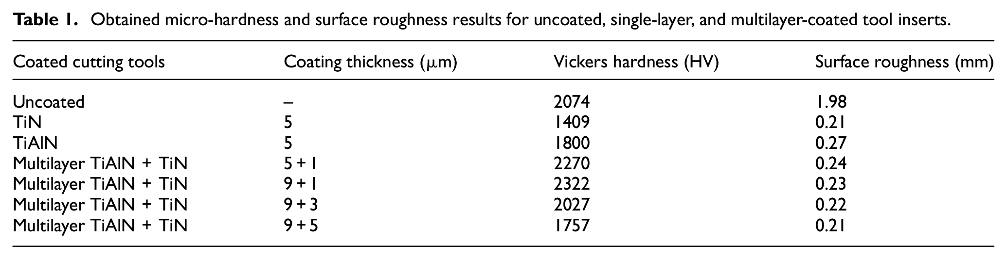
In this research, orthogonal cutting tests under dry cutting conditions were performed on AISI/SAE 4140 alloy steel workpiece material. To carry out machining operations, the Dean Smith and Grace Lathe machine was used on a TCMW 16T304 tool geometry. During experimentation, seven types of cutting tools were used: uncoated; single layered coating (TiN and TiAlN); and multilayered coating [TiAlN/TiN (9 + 5 μm), (9 + 3 μm), (9 + 1μm), and (5 + 1 μm)]. Each layer deposited through the process of Physical Vapor Deposition (PVD). Furthermore, each type of cutting tool insert underwent a micro-hardness testing in a micro-hardness (Buehler 5114) testing machine under a loading capacity of 300 g. Single layer TiN and TiAlN coatings deposited on the carbide P10 tool substrate using PVD process and coated tools loses hardness when temperature increases compared with uncoated tools. TiAlN coating was found high hardness value compared to single layer TiN coating because TiN coating required higher temperature for deposition compared with TiAlN coating. For multilayer coated tools, TiAlN coating was followed by a top layer of TiN. It was observed that TiAlN/TiN (9 + 1) coating has maximum hardness among all the considered coatings. Moreover, to examine the surface finish of the fresh coated tools, the surface finish was measured on the rake face of the fresh cutting inserts using a Wyko 1100 NT white-light interferometer. The average surface roughness was determined at regular intervals along the contact length of the cutting inserts. These measured micro-hardness and surface roughness results for uncoated, single-layer, and multilayer-coated tool inserts are presented in Table 1.
Obtained micro-hardness and surface roughness results for uncoated, single-layer, and multilayer-coated tool inserts.
For the purpose of experimentation, a workpiece material with a length of 150-mm, diameter of 200-mm, and wall thickness of 2.5-mm was used. Moreover, cutting tests were done over cutting speeds of eight different types: (100, 197, 314, 395, 565, 628, 785, and 880) m/min. Subsequently, for every change in the cutting speed, a new cutting edge was utilized for enhanced performance. Experimental tests for each cutting speed were repeated thrice to minimize the errors and to ensure the accurate and reliable readings. After the cutting operation, used tools were examined using a special purpose microscope (Scanning Electron), which further underwent an Energy Dispersive X-ray Analysis (EDXA). Additionally, cutting and feed forces were measured with the help of a Kistler 9263 dynamometer while keeping depth of cut and feedrate as constant values of 2.5-mm and 0.1-mm/rev, respectively. A high-resolution IR thermal imaging camera known as ThermaCAM model SC3000 by FLIR was used to measure cutting temperatures. The camera specifications are: thermal sensitivity of 20 mK @ 30°C; image resolution of 320 × 240; and spectral range between 8 and 9 µm. All the captured images during experimentation were then transferred to an attached PC, which were further analyzed through a built-in FLIR software. Figure 1 below shows the complete experimental setup for machining operation.
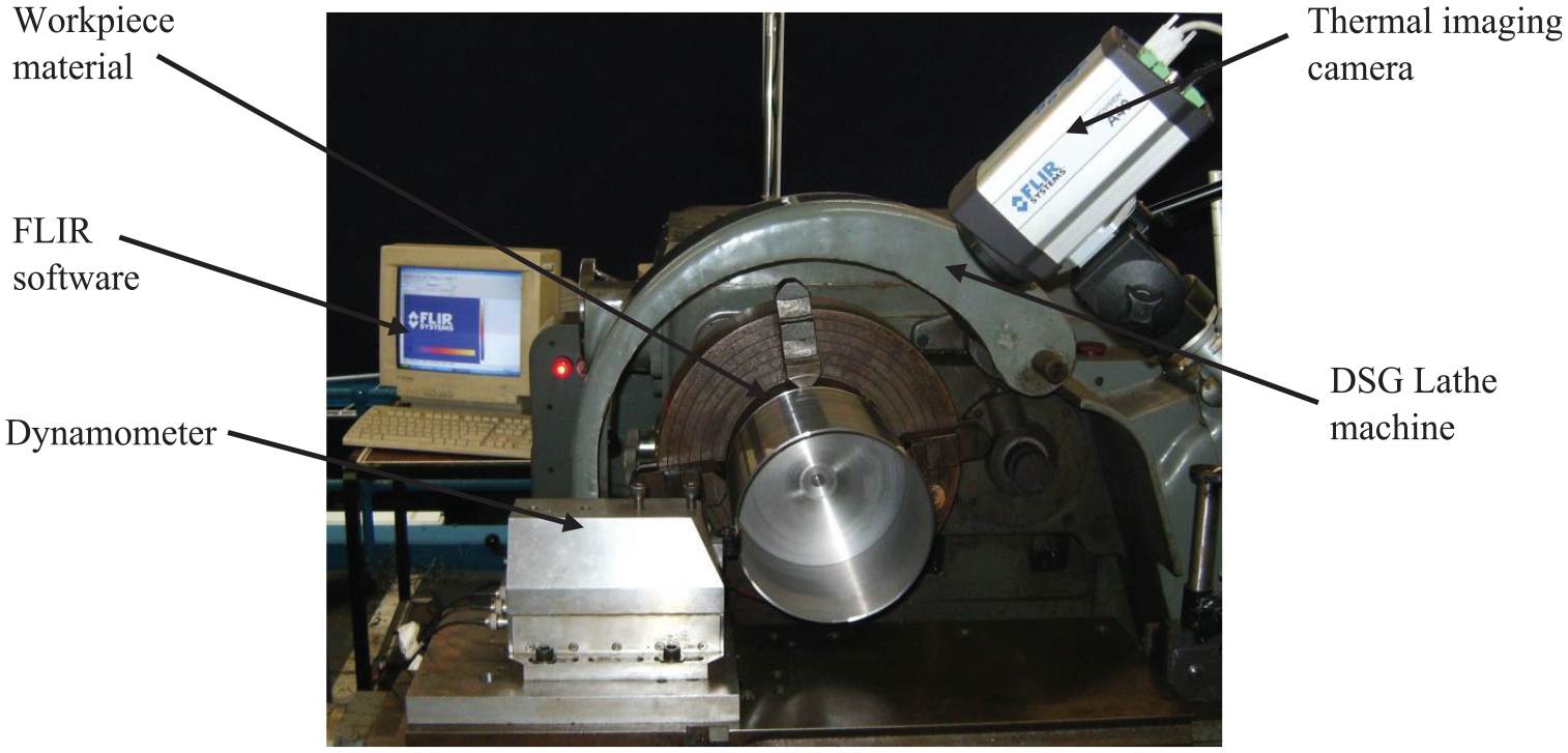
Experimental arrangement for the machining of AISI/SAE 4140 alloy steel.
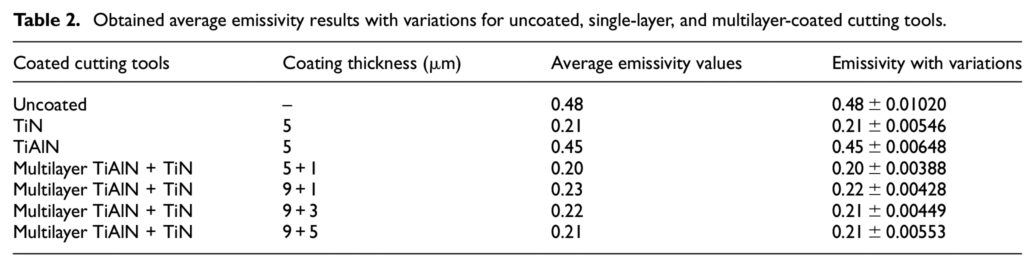
When measuring actual temperatures, emissivity values play a vital. For this purpose, a highly observed calibration was performed of the thermos graphic system for all tool types, which include uncoated, single layer coated, and multilayer coated tools. For this purpose, the material temperatures were raised between 100°C to 900°C, and while capturing the temperature of the tool inserts via a ThermaCAM, emissivity values were also adjusted so as to match its values with those obtained with the help of a thermocouple reader. For better results, 15 values of emissivity were recorded for each temperature level and mean value utilized for setting-up the camera. Thus, the average emissivity values for uncoated, single layer coated, and multilayer coated tools were calculated and are presented in the below Table 2 @ 700°C, which showed changing values. Furthermore, the values had minor change between the range of 450–900°C, which are shown in the variation column.
Obtained average emissivity results with variations for uncoated, single-layer, and multilayer-coated cutting tools.
Cutting tool and workpiece materials
In this investigation, an uncoated cemented carbide, tungsten-based cutting tool along with two single layer and four multilayer coated tools were used. The inserts utilized were in triangular shape as TCMW 16T304 (ISO grade P10) having thickness of 3.97 mm, nose radius of 0.4 mm, and a clearance angle of 7°. The single layered tools were coated with TiN and TiAlN, each of 5 µm thick layer (Figure 2(a) and (b), respectively). All the images in Figure 2(a) to (f) represent the cross-sectional view taken via SEM, which helped measure the coating thicknesses of the tools being utilized.
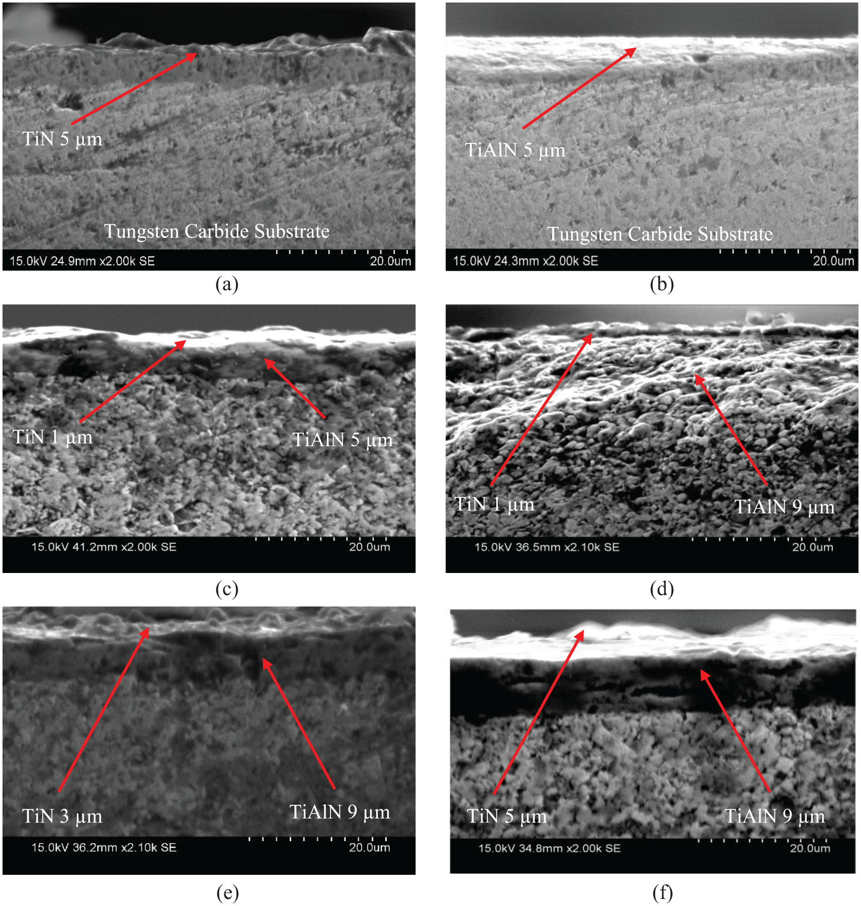
Microscopic cross-sectional images of (a, b) single layer tools and (c–f) multilayer tools.
Furthermore, multilayer coatings were also analyzed during the experimentation in four different coating thicknesses of TiAlN/TiN, as described in Table 1. Note that TiAlN was used as the first layer from the Tungsten Carbide (WC) substrate owing to its better adhesion property, whereas TiN was used as the second layer (top layer) owing to its better sliding behavior that rendered smooth machining operation and less sticking of the chip remnants on the cutting-tool material. The SEM images of the cross-sectional views for four different multilayered coating thicknesses of TiAlN/TiN on the cutting-tool have been shown in Figure 2(c) to (f), with specified thicknesses as 6, 10, 12, and 14 µm, respectively. For cutting operation, a high performance tensile steel alloy (AISI/SAE 4140) was used. Before coatings were applied, the workpiece material had an HRC hardness of 23.9. Table 3 highlights the chemical composition recorded via SEM for the workpiece material.
Weight % of chemical composition for AISI/SAE 4140 alloy steel.
Results and discussion
Cutting and feed forces
Graphical results in Figure 3 showed that uncoated cutting tool required more cutting force than single layer and multilayer coated tools. Furthermore, with the addition of coatings, the cutting forces decreased drastically, and continued to decrease as the speed increased from conventional speed of 100 m/min to HSM at 880 m/min. Increase the cutting speed to reduce cutting forces values is the most frequent method used by researchers.18,21,46–49 High temperature at the flow zone increased hardens of coating and decreased tool-chip contact area, except for uncoated cutting tool, which is considered to be the main reasons of this inverse proportion. Furthermore, the reduction amount in cutting forces can depend on workpiece material, working conditions, and ranges of cutting velocities. Thus, reduction in cutting forces turned out to be beneficial for cutting operation in the HSM domain. 50 Subsequently, in comparison to the uncoated tool, the highest multilayer coating of TiAlN/TiN (9 + 5 = 14 μm) reduced the cutting force from 631 to 455 N at 100 m/min (Figure 3), which was about 72%. The same way, a continuous decrease in the cutting forces was observed as the speed was changed from conventional to HSM.
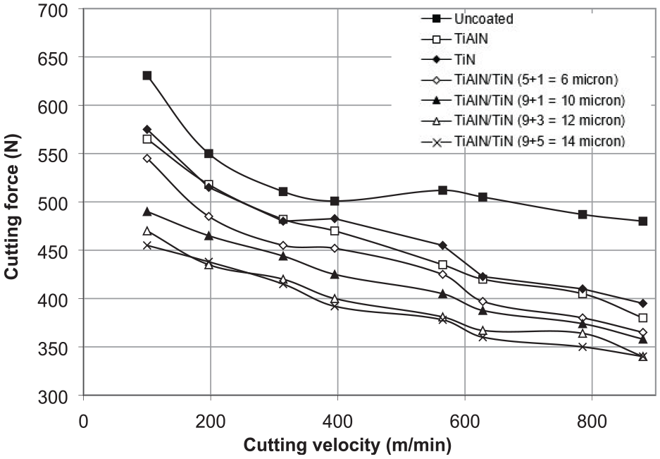
Deviation in cutting force with cutting speed.
Similar to the cutting forces, feed forces also showed a decreasing trend as the speed varied from 100 to 880 m/min, as evident in Figure 4. In addition, as the thickness of the multilayer coating was increased, the feed force decreased. Furthermore, owing to smooth edge of cutting tool and the associated lubricity effect due to added layers of TiAlN/TiN, friction was reduced and built-up edges were prevented, which allowed smooth machining operation.
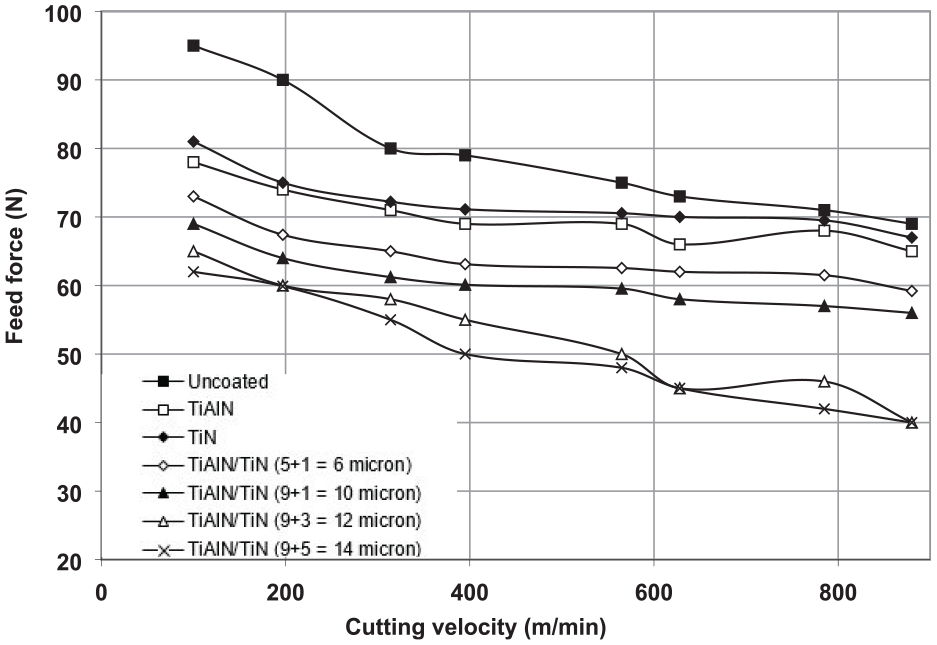
Deviation in feed force with cutting speed.
Chip-tool contact area
The area of contact between chip and tool can greatly influence the machining mechanics and its associated factors such as cutting edge, tool-chip contact zone, heat partition, and heat generation. Note that for every change of speed, new tool was utilized for precise comparison. The SEM images of used tool inserts at varying cutting speeds have been shown in Figure 5. Figure 5 highlighted the chip-tool contact area for uncoated, single, and multi-layer coated tools, respectively (numbered left to right from 1 to 21).
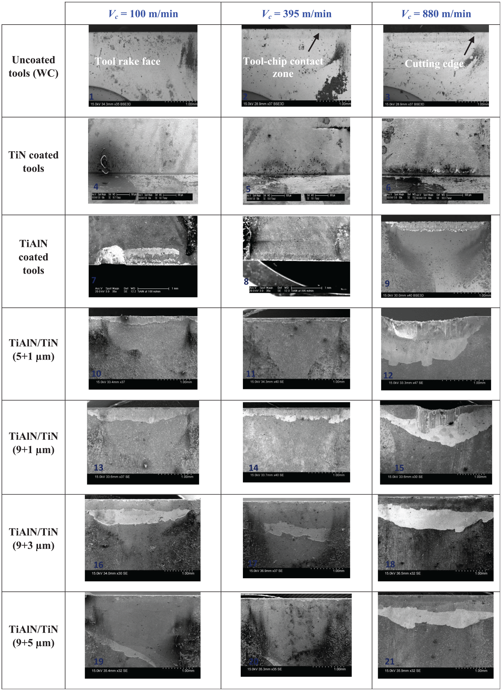
Microscopic images of the chip-tool area of contact for uncoated, single layer, and multilayer coated tools at different cutting speeds.
Figure 6 shows the graphical representation of the chip-tool contact area at varying cutting speeds. It was found that uncoated tool, relative to other coated tools, had larger contact area. However, the variance became more prominent after the speed transition from conventional to HSM (>395 m/min). Furthermore, both single layer and multilayer coated tools had lower contact area mainly because coated layers created a thermal barrier that reduced the excessive flow of heat flux; thus, protecting the material from undue wear and tear and increasing the tool life and its efficiency.
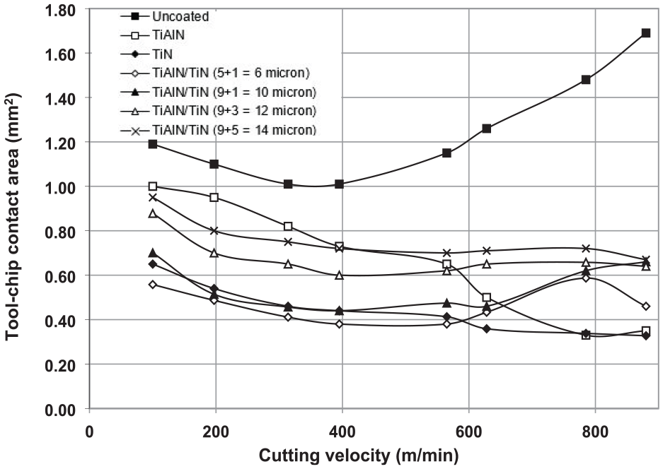
Deviation in the tool-chip contact area with cutting speed.
The TiN single layer coated tool had lower contact area than TiAlN single layer tool because of its good sliding properties. On the other hand, the multilayer coating of TiAlN/TiN (14 µm) appeared to have greater area of contact relative to TiAlN/TiN (9 + 3 µm), (9 + 1 µm), and (5 + 1 µm), as evident from Figure 6. This happened because of the greater influence of bimetallic effect produced by the larger middle-layer thickness of TiAlN in the cutting tool insert. It was worth noting that although multilayer coatings (9 + 5 µm) and (9 + 3 µm) had high contact areas compared to uncoated and other multilayer tool inserts; however, they showed the highest consistency rate of contact areas in HSM region, with only 29% and 27% change in the final value compared to initial contact areas, respectively.
Deformed chip thickness (tc)
During orthogonal dry cutting, the deformed chip thickness for all tool inserts were taken into consideration at varying cutting speeds, as shown in Figure 7. All of these images were captured using a special-purpose microscope (SEM). It was noteworthy that, during machining with uncoated tool, the deformed chip formed was relatively more serrated or non-homogenous than single layer and multilayer coated tool, as evident in the SEM images in Figure 7 (numbered left to right from 1 to 21). The happened due to the decreasing material strength as the temperature was increased at high speed machining, also known as thermal softening of the material. In uncoated tool inserts, due to the absence of added layer, the tool absorbed more heat; thus increasing the tool-chip rubbing friction, which lead to the formation of serrated chip.
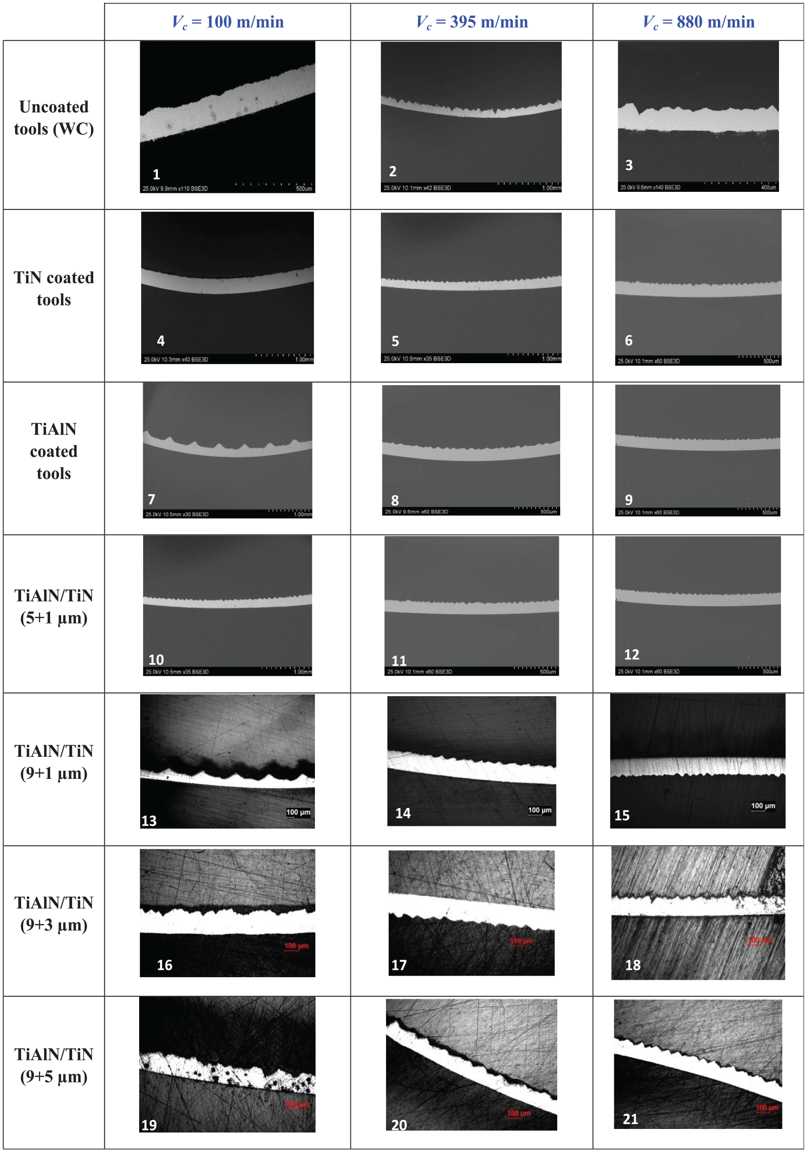
SEM images of chip thickness for uncoated, single layer, and multilayer tools at varying cutting speeds.
Furthermore, the graphical representation of the variation in deformed chip thickness was also recorded, as presented in Figure 8. Results showed that chip thickness was almost the same at 100 m/min for all tool types except for (5 + 1 µm) multilayer tool, which had the lowest deformed chip thickness of about 0.19 mm at 100 m/min. However, it showed the greatest variation relative to other tool inserts in high cutting region (from 785 to 880 m/min), with thickness increased from 0.1 to 0.16 mm (+37.5%). Conversely, the multilayer coating of TiAlN/TiN (9 + 5 µm) was found to perform well in conventional as well as HSM regions, with constant decrement in the deformed chip thickness and lowest value of 0.10 mm in the HSM region (Figure 8).
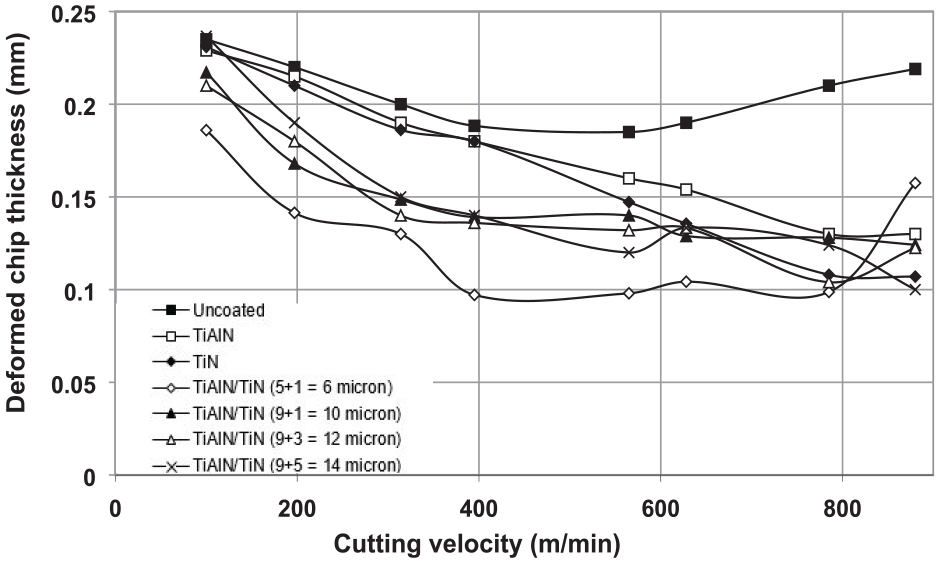
Deviation in deformed chip thickness with varying cutting speed.
Shear angle (Φ)
Figure 9 shows the variation in shear angle at different cutting speeds for each type of tool insert (multilayer, single, and uncoated). Results revealed that shear angle for uncoated and (5 + 1 µm) multilayer tools decreased at speeds greater than 565 m/min. In addition, shear angle for multilayer-coated tool TiAlN/TiN (9 + 3 µm) dropped from 43.88° @ 785 m/min to 39.33° (10.4% drop). However, multilayer coating of TiAlN/TiN (9 + 5 µm) showed the highest increase in the shear angle, from 22.91° at 100 m/min (conventional machining region) to 45° at 880 m/min (HSM region). Thus, the large shear angle for multilayer (9 + 5 µm) coating required less force of cutting and gave smooth surface finish with thin and continuous formation of chip at higher cutting speeds (Figure 9).
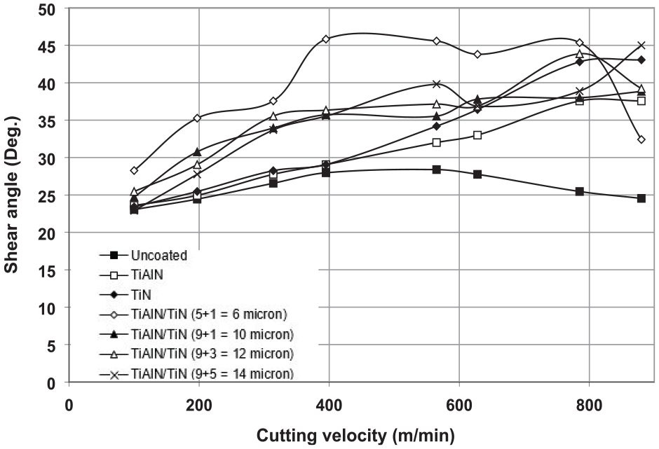
Deviation in shear angle with varying cutting speed.
Chip reduction coefficient (λ)
Figure 10 highlights the variation in chip reduction coefficient at different cutting speeds under identical cutting conditions. Results revealed that uncoated and multilayer (5 + 1 µm) coated tool had minor increment after the cutting speed of 565 m/min. However, the change became more profound as the speed was further increased up until 880 m/min. Thus, forming larger deformed chip than other coated tools. Also, the multilayer (9 + 5 μm) tool had the lowest chip reduction ratio at the cutting speed of 880 m/min, showing a 57% decrease in the HSM region. This showed that multilayer tool (9 + 5 μm) performed well for larger cutting speeds with the lowest thickness of deformed chip.
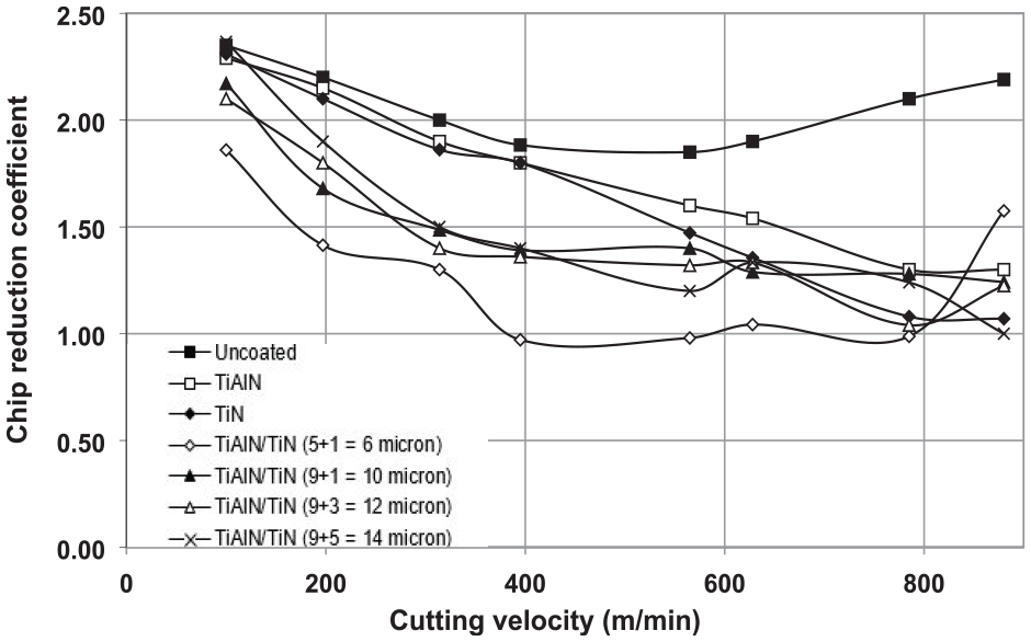
Deviation in chip reduction coefficient with varying cutting speed.
Heat partition ratio (RT)
Figure 11 compares the heat partition ratio for uncoated, single layer coated, and multilayer coated tools. Results showed a decreasing trend heat partition for all tools in conventional machining region. This trend within the conventional cutting speed region is influenced by the well-known 46 decrease in the tool-chip contact area (Figure 6). For uncoated cutting tool, the lower value of heat partition at 395 m/min represents a large part of the heat generated at the tool-chip interface to be carried away by the chip. However, the value for uncoated tool significantly varied in the HSM region (>395 m/min). When the cutting speed is increased above 395 m/min, that is, to the HSM region, the nature of the contact changes and the tool-chip contact length, and hence the contact area, increases. As a consequence, the fraction of heat flowing into the tool increases gradually with the cutting speed and reaches 0.23 at 880 m/min (Figure 11). Thus, the tool-chip contact area is critical in determining heat partition into the cutting tool.
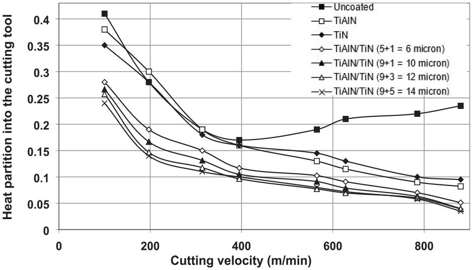
Heat partition variation into the cutting tools with varying cutting speed.
For single layer TiN-coated tools heat partition varies from 0.35 down to 0.095 and for TiAlN-coated tools the heat partition varies from 0.38 down to 0.092. It was worth noting that heat partition ratio dropped prominently when multilayer-coated tool inserts were used for all cutting speeds in conventional and HSM regions. The reason behind this sharp drop was the addition of multilayers that blocked the excessive transfer of heat from chip into the tool via secondary deformation zone. Thus, for (5 + 1 µm) multilayer coated tool, partition of heat dropped from 0.28 to 0.05 (decrement of 82%) for all speed ranges. Similarly, for multilayer (9 + 1 µm), partition of heat reduced from 0.26 to 0.04 (decrement of 84%); for multilayer (9 + 3 µm), partition of heat reduced from 0.25 to 0.03 (decrement of 88%); and for multilayer (9 + 5 µm), partition of heat reduced from 0.24 to 0.03 (decrement of 88%). Therefore, from the results, it transpired that multilayer (9 + 5 µm) coated tool showed the lowest heat partition ratio among all other coated and uncoated tool utilized because the larger thickness of TiAlN produces a stronger influence of the thermal bimetallic effect.
Flank wear
Parallel ridges and abrasive groves characterize the condition of tool. Owing to friction due to rubbing amid the machined side and tool’s flank face, flank wear initiates. This research investigated the average tool flank wear for multilayer, single layer, and uncoated tools. Cutting operation was carried out for speeds between 100–880 m/min and 0.1 mm/rev of constant feed rate, as presented in Figure 12.
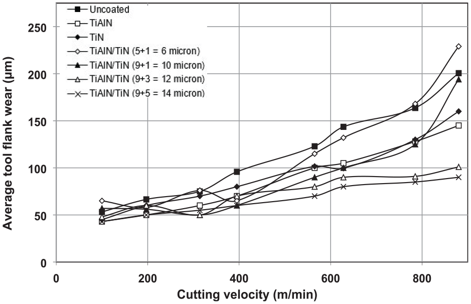
Deviation in tool flank wear with varying cutting speed.
During machining, it was analyzed that average tool flank wear increased mostly in the HSM region (speed >395) for uncoated, TiN (5 µm), TiAlN (5 µm), multilayer (9 + 1 µm), and (5 + 1 µm) coatings. One major reason for faster flank wear rate was early tool softening because of high cutting temperatures at the chip-tool interface. Conversely, multilayer (9 + 3 µm) and (9 + 5 µm) showed consistency in HSM region with comparatively less tool flank wear relative to initial wear (about 52%), Figure 12.
While experimentations, it was found that, for TiAlN/TiN (9 + 5 μm), the flank wear rate decreased relative to other coated and uncoated tool inserts. However, under the cutting edge, the land of the flank wear area appeared to be regular as the cutting velocity was increased. Hence, when TiAlN/TiN (9 + 5 μm) results were compared with other tool inserts, it was seen that flank wear occurred mainly in areas which were isolated with the tool-chip contact. Therefore, for cases where there is excessive rubbing, the generated heat on the rake face of the tool will have an increased effect on the rate of flank wear. Additionally, it was reasonable that excessive wear was attributed to the hardened layer of insulation of the Al2O3 material, which could primarily alter the balance of hart partition ratios by allowing more transfer of heat into the chip.
Conclusions
In this paper, orthogonal dry cutting tests were performed on AISI/SAE 4140 alloy steel workpiece material with a length of 150-mm, diameter of 200-mm, and wall thickness of 2.5-mm. The machining operations were performed on a TCMW 16T304 tool geometry with uncoated, single layer, and multilayer coated tools.
The results of cutting forces showed that with the addition of coatings, the cutting forces decreased drastically, and continued to decrease as the speed increased from conventional aped of 100 m/min to HSM at 880 m/min. In comparison to the uncoated tool, the highest multilayer coating of TiAlN/TiN (9 + 5 = 14 μm) reduced the cutting force from 631 to 455 N at 100 m/min, which was about 72%.
Results for feed forces also showed a decreasing trend as the speed rose from 100 to 880 m/min. The change in the multilayer (9 + 5 = 14 μm) coating was noticeable in comparison to the single layer and uncoated inserts because coatings reduced wear resistance of the tool and rendered enhanced performance.
The multilayer coating (9 + 5 µm) appeared to have bigger area of contact relative to multilayer (9 + 3 µm), (9 + 1 µm), and (5 + 1 µm).
Results also showed that chip thickness was almost the same at 100 m/min. for all tool types except for multilayer (5 + 1 µm) tool, which had the lowest deformed chip thickness of about 0.19 mm @ 100 m/min. However, it showed the greatest variation relative to other tool inserts in the HSM region (from 785 to 880 m/min), with thickness increased from 0.1 to 0.16 mm (+37.5%).
Results for heat partition showed a decreasing trend for all tools. However, the value for uncoated tool significantly varied in the HSM region (speeds >395). Also, from the results, it transpired that (9 + 5 µm) coated tool showed the lowest heat partition coefficient among all other coated and uncoated tool utilized as its heat partition value reduced about 88%.
It was also analyzed that average tool flank wear increased mostly in the HSM region (speeds >395) for uncoated, TiN (5 µm), TiAlN (5 µm), multilayer (9 + 1 µm), and (5 + 1 µm) coated tools. On the contrary, multilayers (9 + 3 µm) and (9 + 5 µm) showed consistency in HSM region with comparatively less tool flank wear relative to initial wear (about 52%).
Footnotes
Acknowledgements
The authors sincerely thank Dr. Muhammad Aslam Sheikh retired as a Reader from The University of Manchester, UK, for his critical discussion on experimental and modelling results and reading during manuscript preparation.
Author Contributions
FA was in charge of the whole trial. MA wrote the manuscript and assisted with the process of analysis. Both authors read and approved the final manuscript.
Declaration of conflicting interests
The author(s) declared no potential conflicts of interest with respect to the research, authorship, and/or publication of this article.
Funding
The author(s) received no financial support for the research, authorship, and/or publication of this article.
Availability of data and materials
All data generated and analyzed during this research work are included in this published article.