
Abstract
Grinding with dicing blade is an important method to cut or slot electronic and optical devices. The deformation of grinding tools will definitely affect the processing of workpiece. However, this effect has been disregarded during processing. In order to improve the machining accuracy in the precision grinding method, this deformation is worth considering. In this research, the grinding state of the ultra-thin dicing blade was simplified as a static problem. The force model of the ultra-thin dicing blade during grinding was established, which centrifugal force was adopted in the whole blade and triangular distribution grinding forces were adopted in the grinding area. The radial deformation of the ultra-thin dicing blade was determined by finite element simulation, and the influence of grinding parameters on its radial deformation was analyzed. The simulation results showed that the grinding area of the ultra-thin dicing blade occurred radial expansion deformation at high rotational speed (more than 8000 rpm), and the value could reach 1.75 μm (rotational speed at 23,000 rpm, feed speed at 600 mm/min, and grinding depth at 0.12 mm). The deformation increased in a form of power function with the increase of rotational speed, and decreased linearly with the increase of feed speed and grinding depth. This work can provide reference data for deformation compensation, which is helpful to improve the dimensional accuracy of grinding groove.
Introduction
As a kind of grinding wheel, an ultra-thin dicing blade is clamped on the dicing saw and usually rotates at high speed, grinding the workpiece in the way of peripheral grinding. Grinding with dicing blade is an important method to cut or slot electronic and optical parts such as silicon wafers, 1 optical splitters, 2 and neural microelectrode arrays. 3 These workpieces are often made of hard and brittle materials, which are not easy to machine, but require high machining accuracy. After machining, there are some problems such as edge chipping, 4 the width of the slit is larger than the thickness of the ultra-thin dicing blade, 5 and the shape deviation of the grinding groove. 6
When grinding grooves, the grinding depth of ultra-thin dicing blade needed to meet high precision requirements. 7 Precision dicing experiments of hard materials with dicing blades showed that the depth of dicing groove after machining was less than set grinding depth. 8 This is probably caused by many factors such as the elastic deformation, wear, and thermal deformation of the grinding tool. 9 As an elastic body, the ultra-thin dicing blade will deform radially under the action of high centrifugal force and grinding force, which will affect actual grinding depth and reduce machining accuracy of workpieces. Therefore, attention should be paid to the stress and deformation of ultra-thin dicing blade during grinding.
There were many researches about the stress and deformation situation of rotating dicing blades. Ma et al. 10 and Ma 11 derived the stress distribution formula of ultra-thin dicing blade when idling at high speed, and obtained the equivalent stress distribution of a dicing blade at different rotational speeds by finite element method. Li et al. 12 proposed the concept of dynamic diameter to describe the outer diameter of a dicing blade affecting by centrifugal force and wear, and investigated the effect of rotational speed on the radial elastic deformation of ultra-thin dicing blade through theoretical analysis and experiment. It was also found that the use of bond with large elastic modulus and low density was beneficial to reduce this radial deformation. High entropy alloy, 13 with excellent above material properties, was tried to add in bond of dicing blades, and smaller radial deformation amount and better grinding groove quality were obtained during grinding. 14 Hu 15 and Callioglu et al. 16 found that the ultra-thin dicing blade would undergo plastic deformation at extremely high rotational speed, and further investigated the elastic/plastic deformation area of the ultra-thin dicing blade. Zou et al. 17 summarized the research progress of radial deformation of ultra-thin dicing blades and illustrated that the researches on the radial deformation influenced by rotation speed were relatively complete. However, the above researches have only considered the influence of centrifugal force. Ultra-thin dicing blades bear centrifugal force and grinding forces during grinding. The lack of considering grinding forces impeded putting these researches further into grinding practice. In order to obtain a more realistic radial deformation of ultra-thin dicing blade, these forces must all be considered.
Grinding forces are produced because abrasive grains rub and cut workpiece in grinding area. Several models have been established to predict grinding/cutting forces, including analytical models, empirical models, finite element models,18–20 and neural network models. 21 The grinding forces of dicing blades were different under different grinding parameters (rotational speed, feed speed, and grinding depth) when grinding, and were widely analyzed. Kim et al. 22 established empirical formulas of grinding forces of the dicing blade through dicing experiments of silicon wafer. However, it was troublesome to determine the coefficients of these empirical formulas, which required a lot of experiments. Yuan et al. 23 proposed a analytical grinding force model basing on failure criterion of brittle materials and considering deviation of cutting width, which total tangential and radial grinding forces of the dicing blade were calculated by the tangential and radial grinding forces of single grain multiply the number of grains participating in cutting. Distributions of grinding forces were also analyzed in some studies. Fujimoto et al. 24 found that the distribution form of grinding forces could be approximated to be triangular though the experiments of creep feed grinding bear steel and measuring the normal and tangential grinding force distribution in the grinding area. Shen et al. 25 established the distribution force model of the dicing blade in cutting off process which grinding forces were seen as a trapezoidal distribution in the contacting arc basing the assumption that the distributed grinding forces were proportional to thickness of chips. These distributed force models had the advantages of simplicity and practicality.
In this study, a force model of ultra-thin dicing blade during stable grinding groove is established for the first time, considering centrifugal force and distributed grinding forces. The radial deformation situation of ultra-thin dicing blade during grinding is obtained by finite element method based on the established force model, and the influence of rotational speed, feed speed, grinding depth on radial deformation is, respectively, analyzed.
Force model of ultra-thin dicing blade during grinding
Experiments on grinding grooves of ultra-thin dicing blades have shown that grinding forces are basically constant in the stable grinding stage. 23 Hence, this work considers that the ultra-thin dicing blade is statically balanced in stable grinding groove stage. The grinding force is usually calculated by the sum of all the individual grain forces in grinding area. 26 Here, for the convenience of handling, this discrete grinding force model is simplified as continuous.
Figure 1(a) presents grinding groove process of an ultra-thin dicing blade which the dicing blade rotates at high rotational speed n and cuts into workpiece at grinding depth ap, and the workpiece moves relative to dicing blade at feed speed vw.


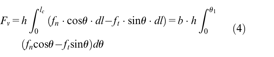
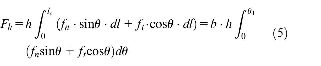
Vertical grinding force Fv can be derived by integrating fn and ft in the vertical direction along grinding area, which is given in equation (4), where h is the thickness and b is the outer radius of a dicing blade. Horizontal grinding force Fh can be derived by integrating fn and ft in the horizontal direction along grinding area, which is given in equation (5). Fv and Fh can be usually measured by a dynamometer in grinding experiments. 22
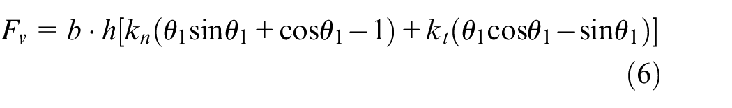
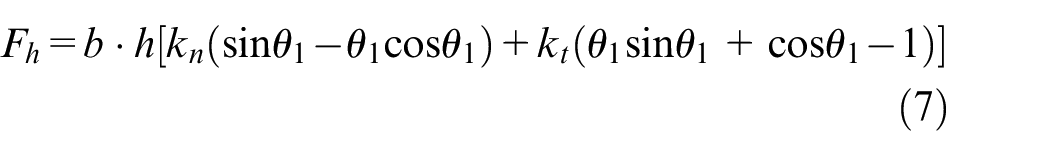
When equations (2) and (3) are substituted into equations (4) and (5), the equations become equations (6) and (7). kn and kt can be obtained by equations (6) and (7), respectively.
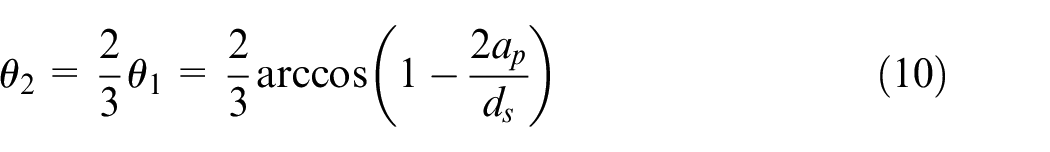
In the analysis of grinding process, normal grinding force Fn and tangential grinding force Ft are commonly used. Fn and Ft can be calculated from Fv and Fh by force vector relationship, which are, respectively, expressed in equations (8) and (9). θ2 is the central angle corresponding to the action point (point B) of total grinding forces which is given in equation (10). 28


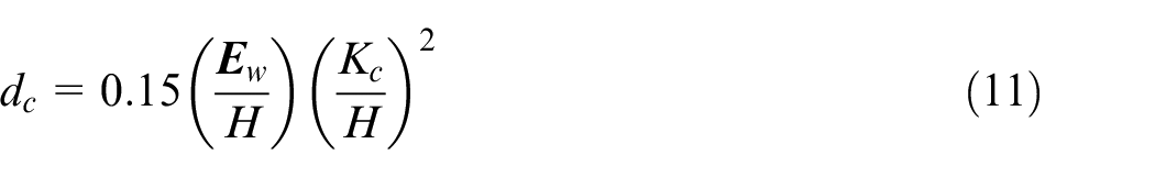
According to indentation fracture mechanics, there is a critical cutting depth dc of plastic/brittle removal mode transition of brittle materials, as shown in equation (11), 29 where Ew, H, and Kc are, respectively, the elastic modulus, hardness, and fracture toughness of workpieces.
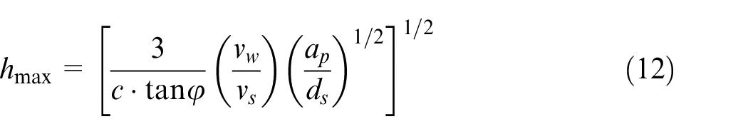
When hmax is less than dc during grinding, the material removal mode of hard and brittle material workpieces are mainly plastic shear removal. hmax is shown in equation (12), 28 where c is the average number of effective abrasive grains per unit area, φ is half of the apex angle of abrasive grains, and ds is the outer diameter of a ultra-thin dicing blade.
The force model of the above-mentioned ultra-thin dicing blade is based on the plastic removal mode of workpieces.
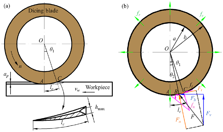
Schematic diagram of grinding with ultra-thin dicing blade and force analysis: (a) grinding process and (b) force model.
Finite element modeling of ultra-thin dicing blade deforming by forces
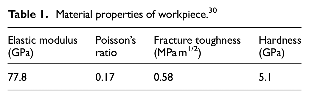
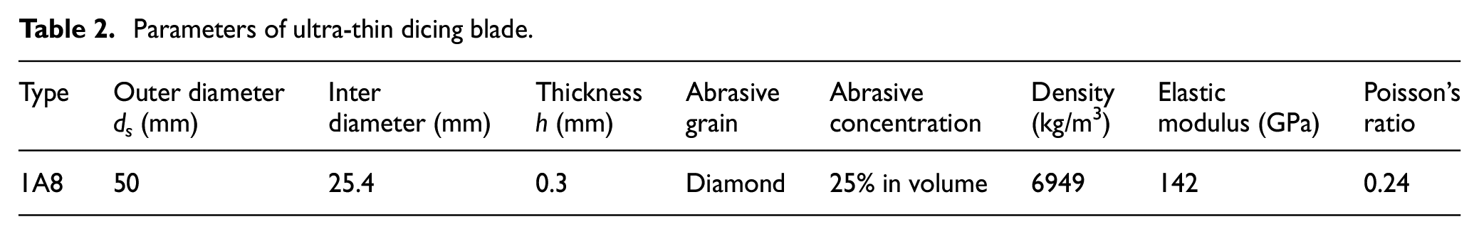
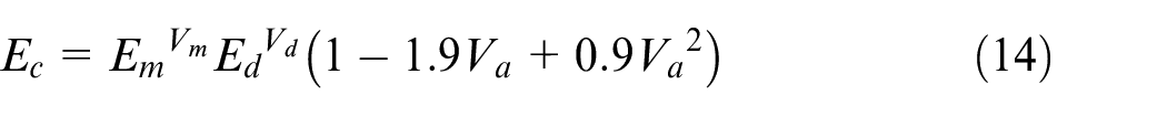
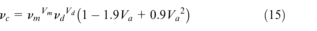
Finite element analysis software Abaqus/Standard is used to study the Mises stress and radial deformation distribution of dicing blade during the high speed and precision dicing quartz glass. The material properties of workpiece are shown in Table 1. 30 The ultra-thin dicing blade is a mixture of bond, superhard abrasive grains, and air pores. This mixture is difficult to simulate in finite element software. Therefore, in simulation, the ultra-thin dicing blade is simplified as a single substance, and the equivalent material properties of composite materials are adopted. The geometric parameters and material properties of ultra-thin dicing blade are shown in Table 2. 31 The density ρc, elastic modulus Ec, and Poisson’s ratio νc of the ultra-thin dicing blade are, respectively, calculated using equations. (13) to (15), 12 where ρm is the density of bond, the main component of the bond in this work is Cu85Sn15, the value of ρm is 8670 kg/m3, 32 ρd is the density of grains, Vd is the volume fraction of grains, ρa is the density of pores, Va is the volume fraction of pores, the value of Va is 5%, Vm is the volume fraction of bond, Em is the elastic modulus of bond, Ed is the elastic modulus of grains, νm is the Poisson’s ratio of bond, and νd is the Poisson’s ratio of grains.
Material properties of workpiece. 30
Parameters of ultra-thin dicing blade.

The data 31 of vertical grinding force and horizontal grinding force measured by grinding quartz glass is substituted into equations (6) and (7), respectively, then kn and kt are obtained. There are 11 trials, as tabulated in Table 3. According to equation (12), hmax at each trial are calculated and the values are all less than dc, which the value of dc is 29.7 nm. 30 Therefore, all trials are based on the plastic removal mode of workpieces.
Grinding force data.
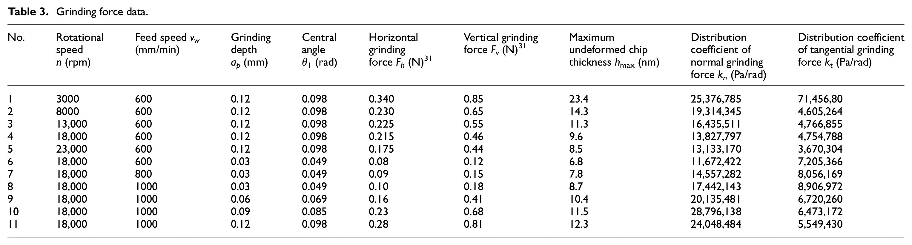
Figure 2 shows the assembly of the ultra-thin dicing blade. The inner hole of the dicing blade forms a shaft hole clearance fit with the circumferential surface of flange A, 12 and the left and right end faces, respectively, contact with the end faces of flange A and flange B. 33 The dicing blade rotates with the spindle under the clamping of two flanges.
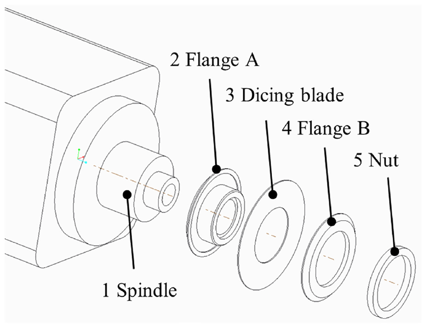
Schematic diagram of assembly situation of ultra-thin dicing blade.
The finite element model of dicing blade deforming by forces during grinding is developed as illustrated in Figure 3. The dicing blade is regarded as the simulated object, and its interaction with other objects is transformed into constraints and loads, and the static force analysis is carried out. The implicit approach is commonly applied to solve this kind of linear static problem in finite element simulation. 34 The loads and constraint conditions are set in cylindrical coordinate system with axes R, T, and Z during simulation. The loads (fr, fn, and ft) are set according to the established force model (see Figure 1(b)). All loads vary with grinding parameters from Table 3. fr is applied to the whole dicing blade in the way of rotation body force. fn and ft are applied to the contact area of outer circumferential surface of the dicing blade in the way of surface force. According to the assembly situation, the constraint conditions of the dicing blade are set as U2 = UR1 = UR2 = UR3 = 0 (means no displacement along axis T and rotation along axes R, T, and Z) at the inner hole surface, and U3 = 0 (means no displacement along axis Z) at the right end face. A eight-node hexahedron element (C3D8R) is utilized to mesh the dicing blade in the way of sweeping and selecting medial axis method. Compared with meshes (dimension at 0.0005 m) of other areas, in the range of −20° to +20°, finer meshes (dimension at 0.0001 m) are used to improve the accuracy and reduce the calculation time. There are six layers of meshes along the thickness direction of the dicing blade.
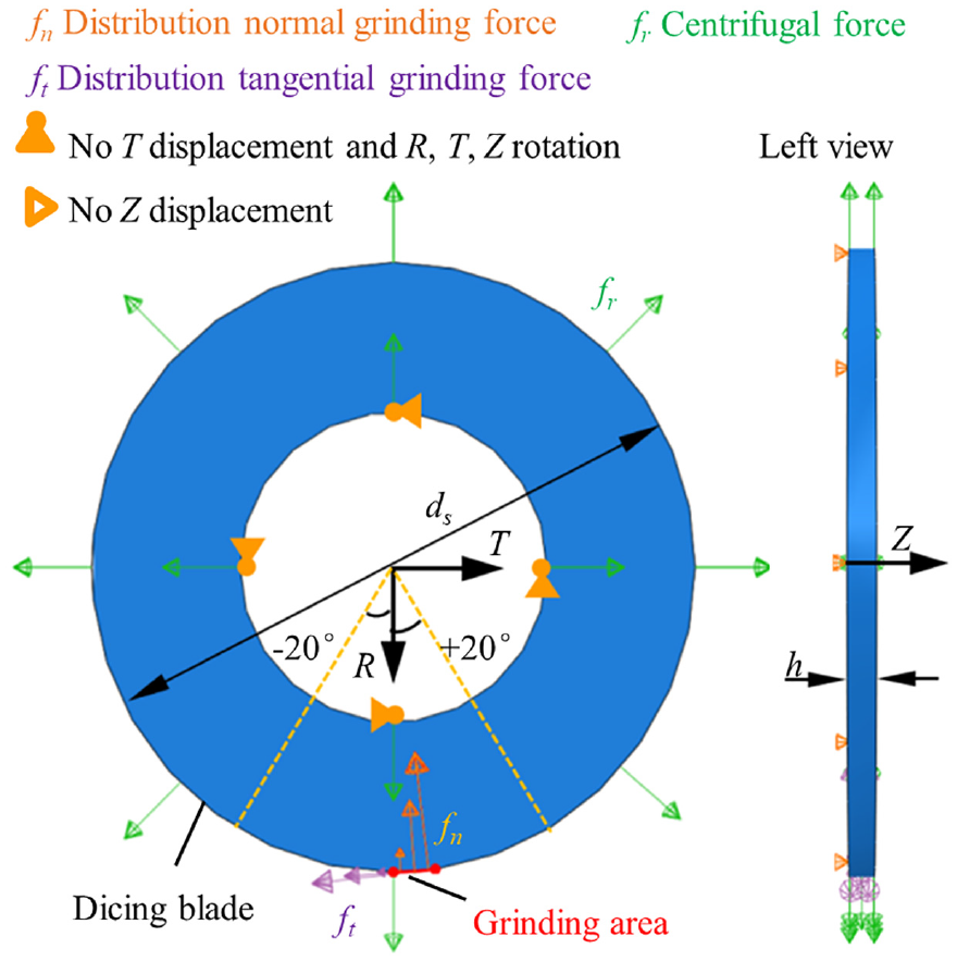
Finite element model of the dicing blade.
Eleven groups of simulations are carried out to obtain Mises stress and radial deformation distribution situation of dicing blade at different grinding parameters from Table 3. Relationship between rotational speed and radial deformation of dicing blade is analyzed in groups of No. 1–5. Effect of feed speed on radial deformation of dicing blade is studied in groups of No. 6–8. Relationship between grinding depth and radial deformation of dicing blade is analyzed in groups of No. 8–11.
Simulation results and discussion
Figure 4(a) depicts the Mises stress distribution of the ultra-thin dicing blade when idling at different rotational speeds. When at n = 3000 rpm, the Mises stress is distributed like an annular contour line, which is equal along the circumferential direction, only changes along the radial direction, and gradually decreases from the inner radius to the outer radius. With the increase of rotational speed, from 3000 to 23,000 rpm, the Mises stress gradually increases. However, the stress distribution remains the same, and the maximum Mises stress points are all at the inner hole, gradually increasing from 0.359 to 21.1 MPa.
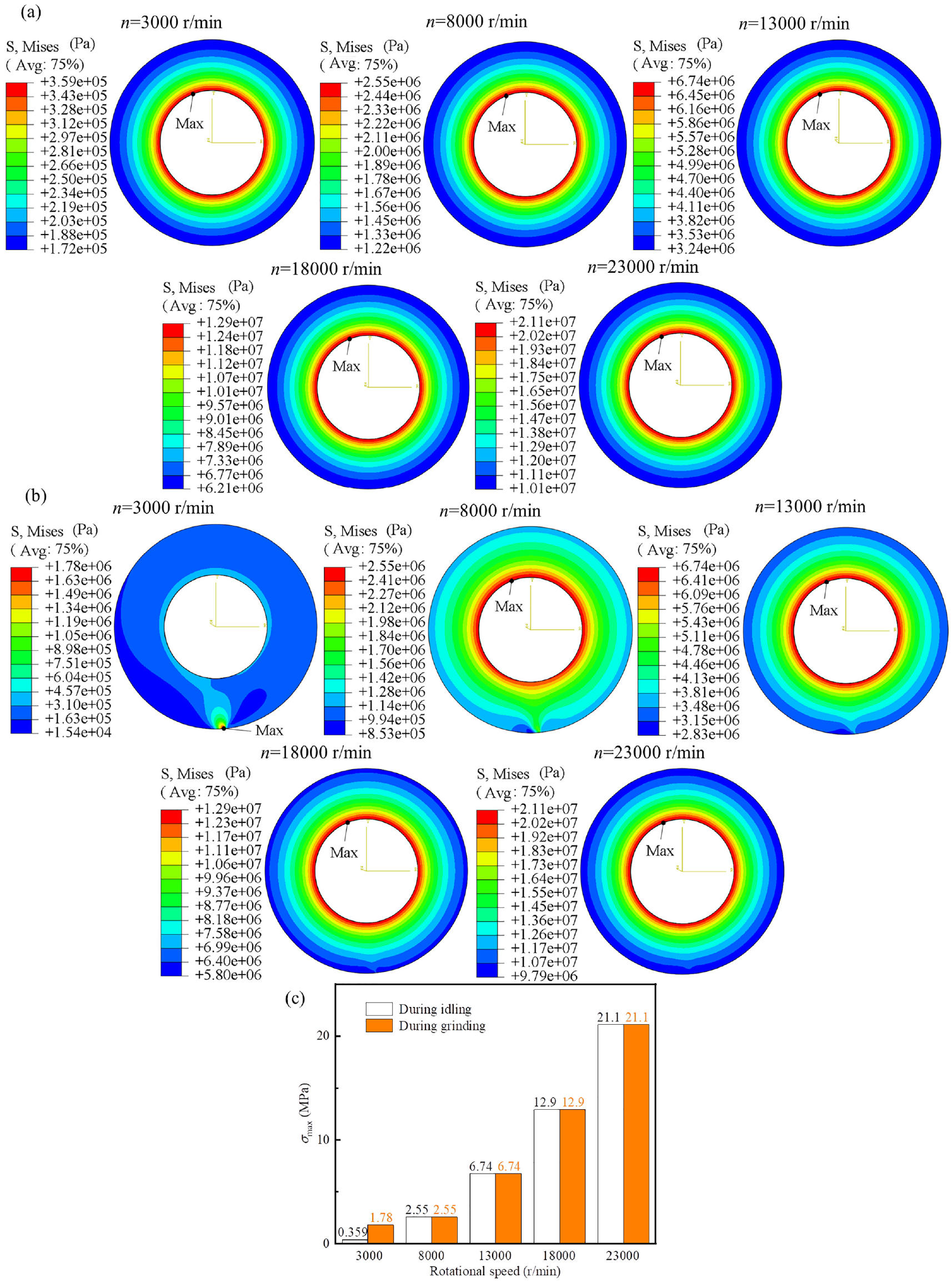
Mises stress distribution of ultra-thin dicing blade at different rotational speeds: (a) cloud images during idling, (b) cloud images during grinding while vw = 600 mm/min and ap = 0.12 mm, and (c) comparison of grinding and idling for maximum Mises stress.
Figure 4(b) shows the Mises stress distribution of the dicing blade at different rotational speeds during grinding. When at n = 3000 rpm, the Mises stress near the grinding area changes violently relative to the overall stress profiles of the dicing blade, and the maximum stress point is at grinding area. With the increase of the rotational speed, the stress change near the grinding area gradually becomes gentle. When the rotational speed reaches 23,000 rpm, the Mises stress is distributed in a multi-layer ring shape, which is same to the stress field of grinding wheel idling in this speed. As revealed in Figure 4(c), from 8000 to 23,000 rpm, the value and position of the maximum Mises stress σmax during grinding are consistent with those during idling. At low speed (3000 rpm), the distributed grinding force has a great local influence. It can be seen from Table 3 that kn at this speed is the largest, fn(θ = θ1) = 2.487 MPa calculated by equation (2), while the centrifugal force is the smallest, and fr(r = b) = 17.129 MPa calculated by equation (1). While at high rotational speed, the grinding force is far less than the centrifugal force, and the influence of grinding force is small.
Figure 5(a) shows the radial deformation of the ultra-thin dicing blade at different rotational speeds during idling. It can be seen that the dicing blade expands radially. The radial deformation decreases from the inner diameter to the outer diameter, and increases with the increase of the rotational speed.
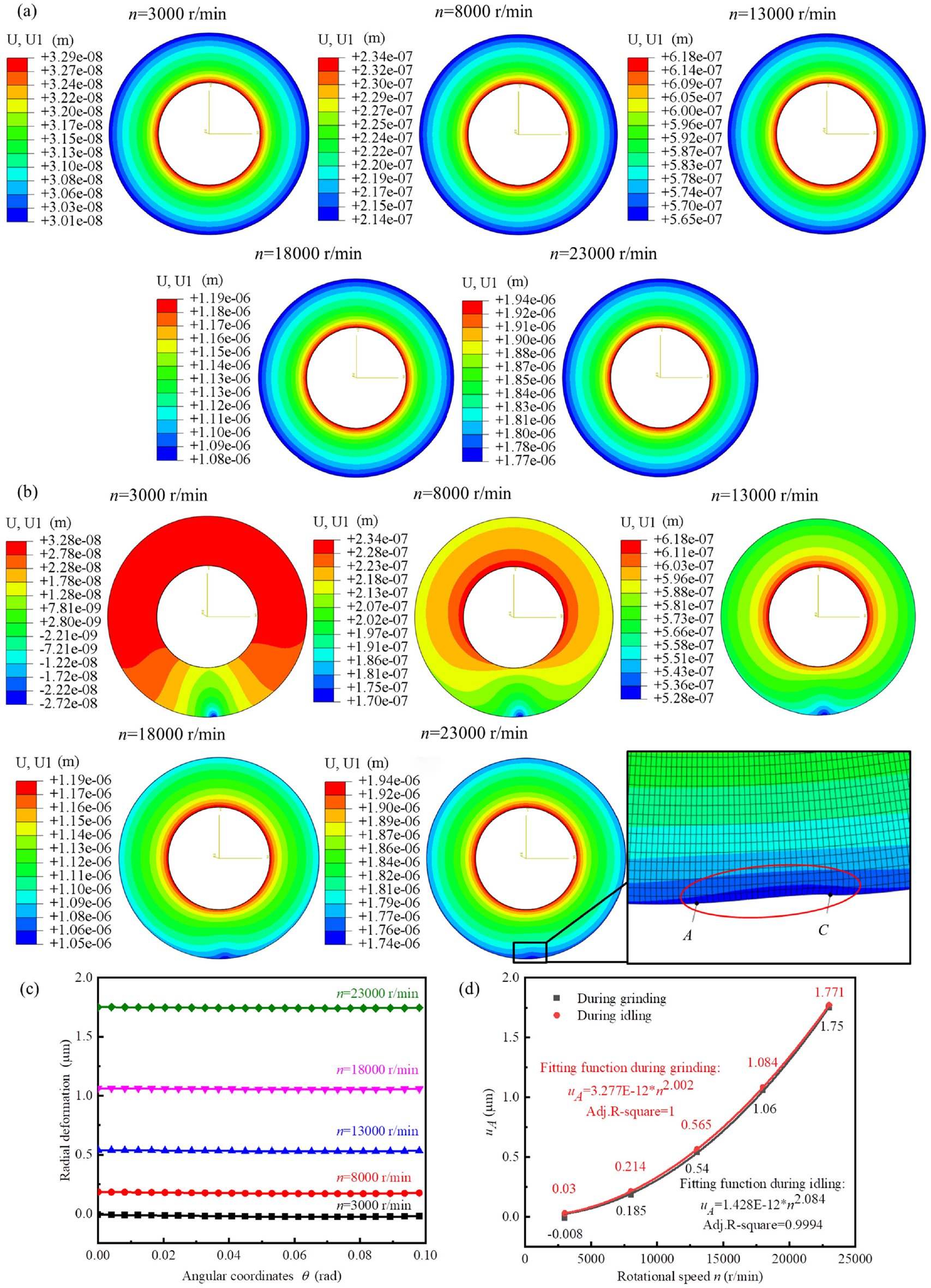
Radial deformation situation of ultra-thin dicing blade at different rotational speeds: (a) during idling, (b) during grinding while vw = 600 mm/min and ap = 0.12 mm, (c) at grinding area, and (d) comparison of grinding and idling at point A.
As presented in Figure 5(b), the radial deformation of the area near the grinding area change sharply during grinding, and the deformation gradually flattens with the increase of the rotational speed. The grinding area of the dicing blade occurs radial compression deformation at n = 3000 rpm. When at n > 3000 rpm, the dicing blade shows radial expansion. Compared with the adjacent outer circumferential area, the grinding area is partially dented at high rotational speed. Figure 5(c) is obtained by extracting the radial deformation data at the grinding area from Figure 5(b). It is revealed that the radial deformation at the grinding area is basically same. The radial deformation of bottom of the dicing blade (at point A) uA directly affects the final forming size of the groove depth. Figure 5(d) depicts relationship between rotational speed and uA, which the data of uA is extracted from Figure 5(a) and (b). As shown in Figure 5(d), uA increases in a power exponential upward trend with the increase of rotational speed during idling and grinding, and the deformation during grinding is slightly smaller than that during idling because grinding force counteracts a small amount of the radial expansion deformation caused by centrifugal force during grinding. However, with the increase of rotational speed, the influence of grinding force on radial deformation gradually weakens.
Figure 6 shows the Mises stress distribution at different feed speeds during grinding of ultra-thin dicing blades. With the increase of feed speed, the maximum stress points all appear at the inner hole, all of which are 12.9 MPa, which is the same as the result of the same idling speed. The change of stress distribution at different feed speeds is not obvious, because the centrifugal force at high speed is far greater than the grinding force.
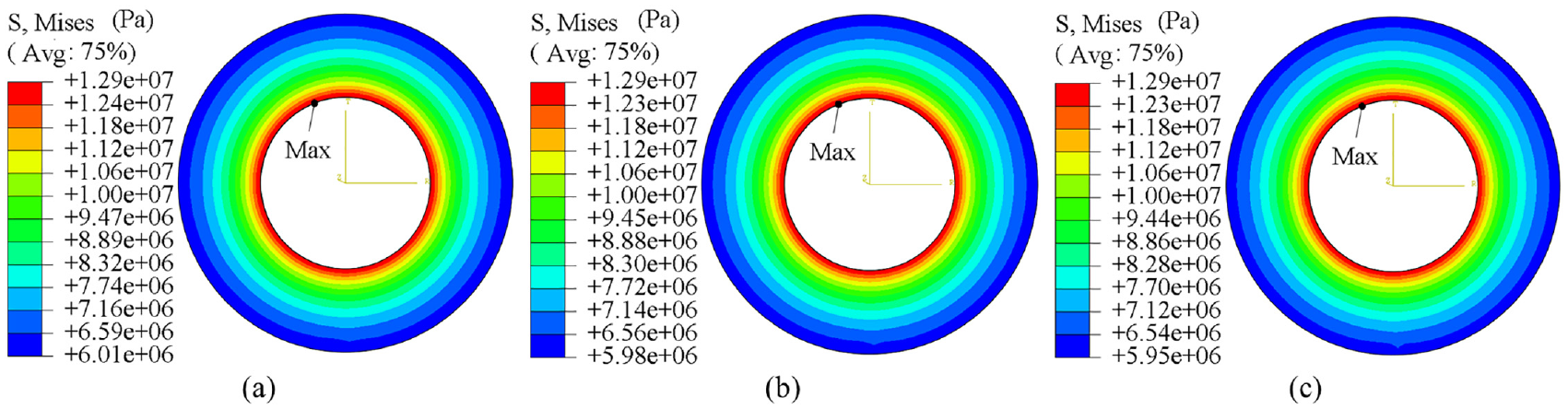
Mises stress distribution of ultra-thin dicing blade during grinding at different feed speeds while n = 18,000 rpm and ap = 0.03 mm: (a) vw = 600 mm/min, (b) vw = 800 mm/min, and (c) vw = 1000 mm/min.
Figure 7(a) shows the radial deformation of the dicing blade at different feed speeds during grinding. The radial deformation situations are similar. As shown in Figure 7(b), the radial deformation of grinding area decreases with the increase of feed speed, and the radial deformation of each point in grinding area decreases with the increase of its corresponding central angle. The radial deformation at the end of the grinding area shows an abnormal increasing trend. This phenomenon is related to the stress distribution. From Figure 7(c), it can be seen that the fn and ft after simulation at the end of the grinding area are on the rise, which are inconsistent with the setting distribution grinding forces because of the slightly distorted mesh and the calculation method of node stress in simulation. Figure 7(d) presents that with the increase of feed speed, uA decreases linearly because the normal grinding force and tangential grinding force both increase with the increase of feed speed and counteract expansion deformation caused by centrifugal force. However, the change is small, because the centrifugal force at high speed is far greater than the grinding forces.
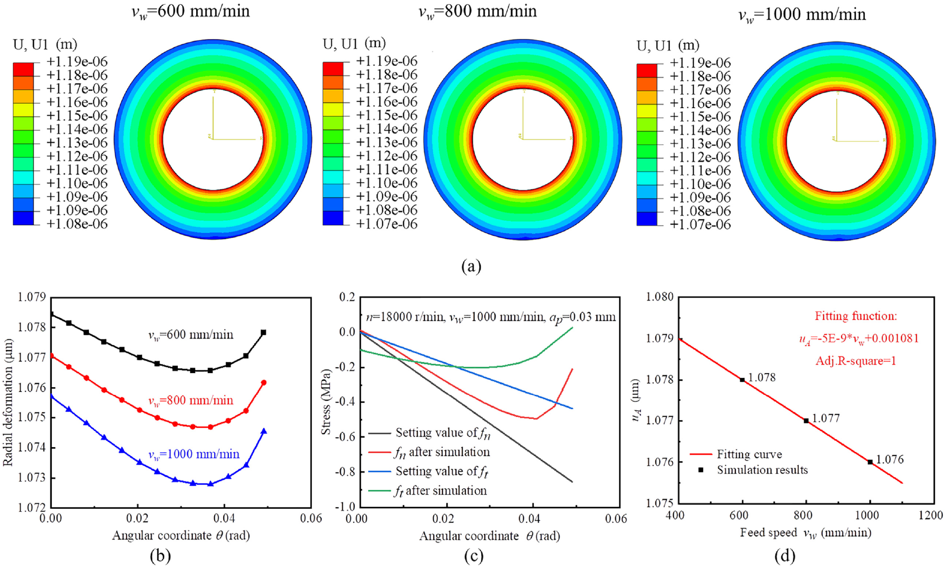
Radial deformation situation of ultra-thin dicing blade during grinding at different feed speeds while n = 18,000 rpm and ap = 0.03 mm: (a) cloud images of radial displacement distribution, (b) comparison at grinding area, (c) stress situation of grinding area, and (d) comparison at point A.
Figure 8 presents that the Mises stress of dicing blade at different grinding depths all show a gradual decrease from the inner diameter to the outer diameter as a whole. The maximum Mises stress points all occur at the inner hole, all of which are 12.9 MPa. With the increase of grinding depth, the change of Mises stress near the grinding area is more obvious.
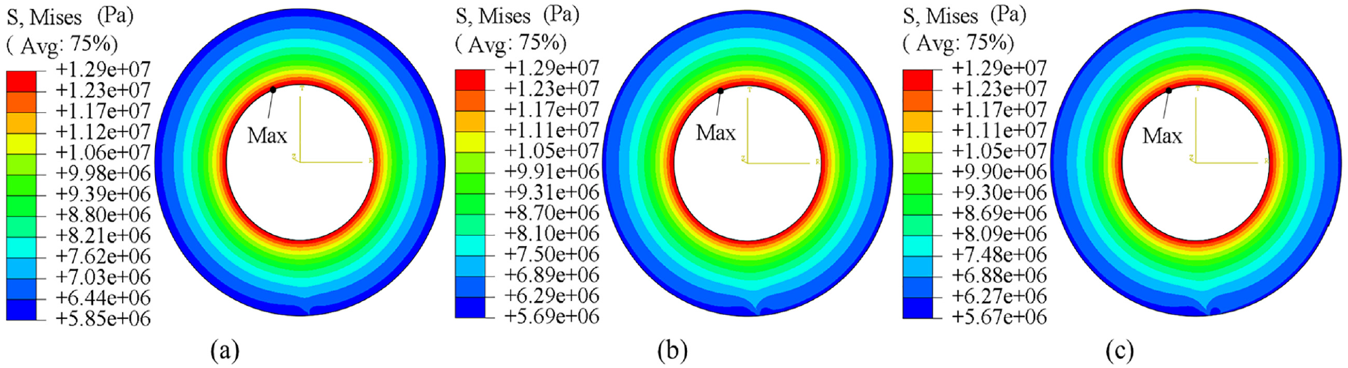
Mises stress distribution of ultra-thin dicing blade during grinding at different grinding depths while n = 18,000 rpm and vw = 1000 mm/min: (a) ap = 0.06 mm, (b) ap = 0.09 mm, and (c) ap = 0.12 mm.
Figure 9(a) shows the radial deformation of the dicing blade at different grinding depths. With the increase of grinding depth, the radial deformation of the area near the grinding area becomes more severe, and the radial deformation of the grinding area gradually decreases, as shown in Figure 9(b). This is because both normal grinding force and tangential grinding force increase with the increase of grinding depth. Figure 9(c) presents that uA gradually decreases in a linear downward trend, but the change is small, because the centrifugal force at high speed is far greater than the grinding force.
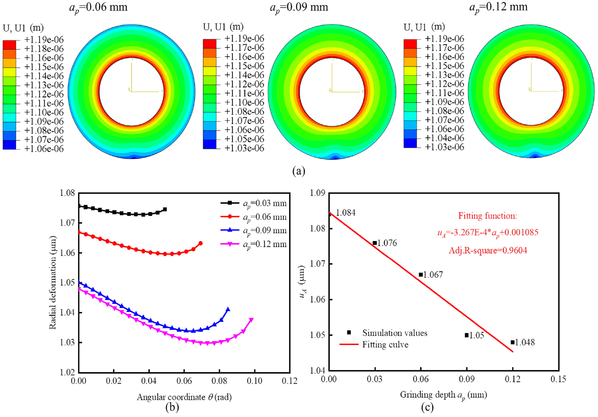
Radial deformation situation of ultra-thin dicing blade during grinding at different grinding depths while n = 18,000 rpm and vw = 1000 mm/min: (a) cloud images of radial displacement distribution, comparison at (b) grinding area and (c) point A.
Finite element simulation results of uA during idling are compared with the existing theoretical calculation results and measurement results, 12 in the same conditions about the size parameters and material properties of dicing blade and force model only considering centrifugal force. The comparison results are shown in Figure 10. It can be seen that deformation simulation values are basically consistent with theoretical calculation values, and also consistent with the change trend of experimental values. The obtained stress distribution situation is also consistent with the existing research. 10 This shows that the finite element model has good accuracy and the results are credible.
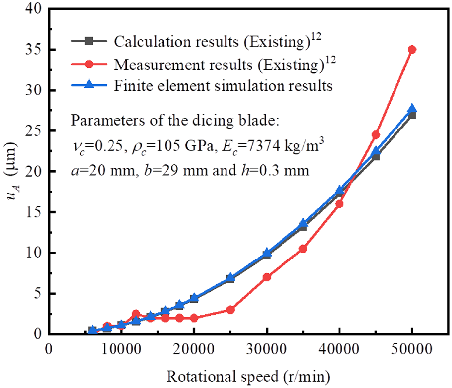
Comparison of radial deformation between simulation results and existing reference results.
In conclusion, the relationship between grinding parameters and radial deformation is established. Changes in grinding parameters cause changes in centrifugal force and grinding forces. The dicing blade deforms by these forces. With the increase of rotational speed, centrifugal force increase significantly, while grinding forces decrease due to the decrease of maximum undeformed chip thickness. With the increase of feed speed, the material removal rate will increase, and the chip thickness increase, which lead to the increase of grinding forces. With the increase of grinding depth, the material removal rate and grinding arc length increase, then chip thickness and effective abrasive grains increase, which lead to the increase of grinding forces. The radial deformation at the lowest point of grinding area of ultra-thin dicing blade increases with the increase of rotating speed, and decreases linearly with the increase of feed speed and grinding depth. Comparing Figures 5(d), 7(d), and 9(c), the rotational speed has the greatest influence degree, the grinding depth has the second influence, and the feed speed has the smallest influence. In high-speed grinding, it is difficult to completely offset the radial deformation by adjusting the combination of grinding parameters. In order to improve the dimensional accuracy of grinding grooves, it may be a suitable idea to compensate the radial deformation to grinding depth. As the special precision machine for dicing blades, the moving resolution of Z axis of dicing saw can reach 0.05 μm, for example, DISCO DAD3350 automatic dicing saw (DISCO Corporation, Japan). 35 This means that the compensation is technically feasible, and it needs further experimental verification. This work can provide reference data for deformation compensation.
When grinding, the Mises stress and radial deformation distribution near the grinding area of ultra-thin dicing blades are complicated, and it is difficult to express them by analytical expressions. There is a also pity that it is difficult to directly measure the radial deformation of the dicing blade during grinding through experiments because the grinding area is in the groove. In pursuit of higher accuracy, finite element simulation in actual grinding is a more effective means.
Grinding with a dicing blade is a processing method of ultra-precision grinding, which technically belongs to creep feed grinding or high efficiency deep grinding. 36 The radial deformation of grinding wheel during grinding was investigated considering thermal deformation and elastic deformation caused by centrifugal force.37–39 The stress distribution and radial deformation laws of grinding wheel under centrifugal force are consistent with that of dicing blade based on same theoretical calculation formulas.12,39 That means that the research content of this work is also applicable to grinding wheels because their grinding mechanism and force conditions are consistent, especially for precision grinding of narrow and deep grooves. However, this work only carried out the static simulation under the simplified grinding force model. In the follow-up researches, the distribution of grinding force should be further determined, and the grinding force model should be optimized. More factors should be carried out to be more realistic, such as wear and thermal deformation of dicing blades.
Conclusions
The radial deformation of ultra-thin dicing blade can reach 1.75 μm (at n = 23,000 rpm, vw = 600 mm/min, and ap = 0.12 mm), which can’t be ignored in precision grinding. The deformation increases in a form of power function with the increase of rotational speed, and decreases linearly with the increase of feed speed and grinding depth. Among them, the rotational speed has the greatest influence, followed by the grinding depth, and the feed speed has the least influence.
At high rotational speed (n > 8000 rpm), the grinding area of the dicing blade is radially expanded and deformed. Grinding force can offset some radial expansion deformation caused by centrifugal force, but, it is difficult to completely offset the radial deformation by optimizing the combination of grinding parameters. In order to reduce the influence of radial deformation of ultra-thin dicing blade on the machining accuracy of workpiece, compensation deformation can be considered.
This work determines the radial deformation of ultra-thin dicing blade during grinding, which will provide reference data for deformation compensation. At the same time, it will provide suggestions for optimization of grinding process parameters, which is helpful to improve the dimensional accuracy of grinding grooves, and has significant engineering significance.
Footnotes
Appendix
Declaration of conflicting interests
The author(s) declared no potential conflicts of interest with respect to the research, authorship, and/or publication of this article.
Funding
The author(s) disclosed receipt of the following financial support for the research, authorship, and/or publication of this article: This work was supported by Science and Technology Project of Hebei Education Department, China (ZD2021099).