
Abstract
Due to variable cross-sections and a thin-walled structure, gas turbine blades have stringent dimensional, and geometrical tolerance requirements. Single-crystal hollow blades are manufactured using the following investment casting processes: ceramic core preparation, wax injection, ceramic coating, wax removal, metal casting, and finishing. The main causes of the final casting deformation are wax pattern deformation, core deflection, and metal solidification warpage. This paper proposes a numerical simulation method to predict the deformation of the wax pattern, core deflection, and the directional solidification (DS) process of large single-crystal blades. Additionally, it investigates the displacement field and the influence of casting process parameters on dimensional accuracy. Three groups of DS process parameters were selected for experiments, and the deformation prediction was in agreement with the experimental results. The selected blade section deformation is the smallest when the pouring temperature is 1530°C and the withdrawal rate is 5 mm/min. The proposed finite element model is efficient to predict the deformation in all the investment casting processes, providing geometric guidance for the control of the dimensional accuracy of the turbine blade.
Introduction
Investment casting process (ICP) provides a high degree of dimensional accuracy and therefore plays an irreplaceable role in producing high-quality parts with intricate shapes. 1 Nickel-based superalloys are widely used in manufacturing turbine blades, because of high temperature fatigue resistance, creep strength, and corrosion resistance. 2 Nickel-based single-crystal (SC) superalloy cast blades can be developed by applying material genetic engineering techniques.3,4 Heavy-duty gas turbines with natural gas as an energy source have the advantages of high efficiency, low emissions, and high peaking capacity. As the main component of the turbine vortex section, the turbine blades operate under extreme and complex environmental conditions, and the blade body is usually designed as a variable cross-section with a thin-walled structure. 5 The dimensional accuracy of turbine blades is important not only for the smooth installation of the gas turbine, but also for efficient energy conversion. 6 The blade body has a complex curvature with nonlinear thickness. Moreover, ICP is sophisticated, each stage of which affects the final dimensional accuracy of the blade.7,8 With the upgrade of the aero engine’s thrust-to-weight ratio and the development of cooling air injection, the dimensional and geometrical tolerance requirements of the blade are more stringent. 9 Although the geometrical information of the blade castings can be acquired from the design specifications, the produced cast dimensions are smaller than those of the die cavity because of wax shrinkage and alloy directional solidification(DS). 10 The characteristics of turbine blades manufactured with DS (i.e. hollow, thin-walled, and complex) make controlling dimensional accuracy difficult. Given the stringent dimensional and geometrical tolerance requirements for turbine blades, new methods are required to predict the deformation of each stage and control the dimensions with an appropriate degree of accuracy.
The main stages of ICP are ceramic core preparation, wax injection, ceramic coating, wax removal, metal casting, and finishing. Within these stages, many smaller processes are involved, such as die construction, wax injection, slurry coating and stuccoing, dewaxing, roasting, and casting. 11 All these stages have their own complexities and pose a potential and uncertain risk to the accuracy of the dimensions of the final part. Furthermore, not only does the process of producing the blade casting cause volume shrinkage, but the variation in the geometric features also obeys a certain pattern, resulting in deformation and dimensional deflection of the casting. 12 Hence, it is necessary to investigate each stage of the ICP, including the wax pattern injection of the ceramic core and blades, core deflection, and the DS process. Liu 11 established the state space model to describe the accumulation and transmission of the variation. The system transmitting matrix A(k) expresses the relationship between previous stages and the current stage. Gebelin 7 investigated different stages of ICP: wax pattern injection, de-waxing, and casting. By comparing experimental and numerical results, Gebelin revealed some shortcomings of commercial software. Sabau 12 used die–wax, wax–shell, and shell–alloy interactions to predict shrinkage factors and final casting in a coupled manner.
With the increasing sophistication of computer hardware and software, numerical simulation of wax patterns and casting is becoming more accessible.13,14 Due to the high price of nickel-based SC superalloys and the cumbersome test cycle, it is difficult to optimize the processing technology through experimental research. Numerical simulation, however, can solve this problem. Jiang et al. 15 proposed a novel compensation model for the wax pattern die of a turbine blade and conducted two numerical experiments for the purpose of demonstration. Reddy et al. 16 used a numerical simulation of a vacuum investment DS high-pressure turbine blade by pouring molten CM247LC superalloy into an investment mullite mold to confirm that the grain growth proceeded from bottom to top, which is the opposite direction from the heat extraction and prime requirement of Yang et al. 17 used ProCAST in the gravity and centrifugal investment casting of turbine blades and concluded that the internal and external quality of the centrifugal casting was much better than that of gravity casting. From previous studies, it can be concluded that solidification simulation has been widely used to predict residual stress and shrinkage during ICP. Several commercial software suites, such as MOLDFLOW and ProCAST, have been employed to investigate wax patterns and the casting process.
Over the last few decades, DS has led to the development of SC superalloy castings.18–20 Several possible methods have been evaluated for DS, which includes liquid metal cooling (LMC) and high-rate solidification (HRS). Due to the low heat-transfer rate of HRS, however, some defects may occur, such as warping, cracking, freckles, and stray grains. Yan et al. 21 established a multi-scale model of the hollow blade with temperature field, grain growth, and solute diffusion. Yan also introduced the LMC process, discovered the proper withdrawal rate, and investigated the relationship between grain growth and the withdrawal rate. Li et al. 22 used the ProCAST software to carry out DS of Ni-based SC turbine blades by using HRS and LMC. The results showed that LMC process can hold back stray grains by smoothing the concaved isotherm and alleviating the undercooling in the platform ends, allowing the dendrites to fill the undercooled zone before stray grain nucleation. Compared with HRS, the LMC process can provide a larger temperature gradient for the same withdrawal rate, which increases the rate of formation of single or columnar crystals. In accordance with current research, the LMC process can also reduce the shrinkage of castings. 21
This paper is aimed at the deformation prediction of SC turbine blades and dimensional control based on cross-sections analysis. Here we propose a numerical simulation method coupled with experimental verification to determine the dimensional control of the wax pattern of the ceramic core and blades, core deflection, and the DS process while considering the structural characteristics of thin-walled hollow turbine blades during ICP. This method effectively predicts the deformation of wax patterns, core deflection, mushy zone, and displacement field of DS, which provides guidance for the dimensional accuracy control of the turbine blade during the whole ICP.
Materials and methods
Casting model
The research object is a large, hollow SC turbine blade. The blade is a first-stage dynamic blade, which is the high-rotating part under the highest working temperature in the whole turbine. It is difficult to manufacture. The blade structure includes the blade body, the edge, and the rabbet. The blade body is crucial. As shown in Figure 1, the blade is 426.78 mm high and 102.69 mm wide, and the upper rabbet is 176.52 mm high. The blade is hollow with a ceramic core to reduce the blade thickness and accelerate heat dissipation. Sections A1, A2, and A3 are selected for the deformation analysis.
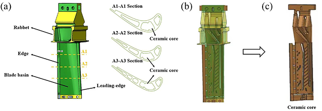
(a) Hollow blade 3D model and cross-sections, (b) assembly, and (c) ceramic core.
Materials properties of wax and superalloy
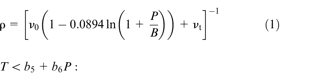
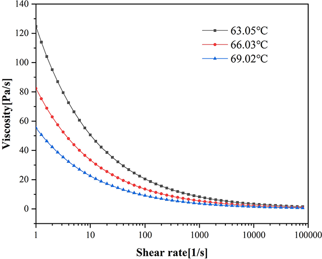
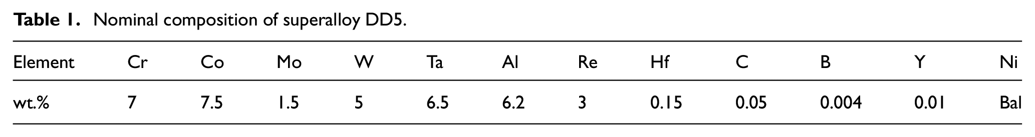
The raw material is the A7-FR80T blade filler wax from Blayson UK, which has the advantage of low melting viscosity and excellent dimensional stability. Figure 2 shows the rheological properties curves of the wax, and Figure 3 shows the PVT (Pressure-Volume-Temperature) curves of the melt compressibility of the wax. Figure 4 shows the thermal performance curves of the wax. The hollow blade is required to have excellent strength, oxidation resistance, and high temperature fatigue resistance due to the harsh working environment. The material of the blade is DD5 superalloy, and the main chemical composition is shown in Table 1. The alloy’s liquid and solid phase temperatures are 1385°C and 1235°C, respectively. The two-domain Tait equation of state is the typical model used in molding simulation. And the equation to describe the specific volume dependency on the pressure and temperature of polymers, is as follows 23 :


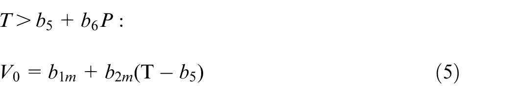


Rheological properties curves of the wax.
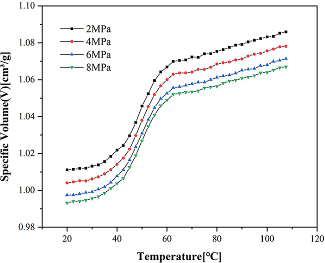
PVT curves of the wax.
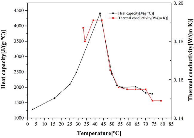
Thermal performance curves of the wax.
Nominal composition of superalloy DD5.
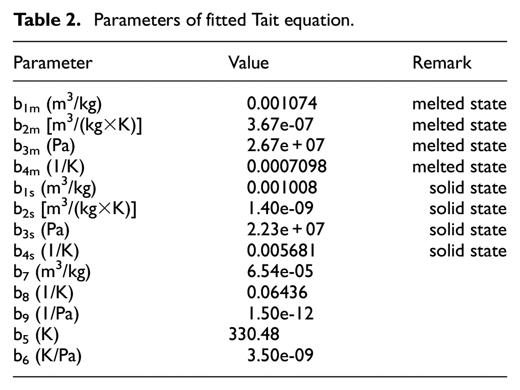
The PVT state equation of polymer is used to describe the PVT relationship of polymers, which provides calculation formulas and a theoretical basis for molding simulation and deformation control. Therefore, the PVT state equation of wax melt under low injection pressure is investigated, and 11 parameters of the Tait equation are fitted by multiple nonlinear regression according to experimental data, as is shown in Table 2, which is the basic theoretical basis for accurate calculation of wax pattern shrinkage deformation.
Parameters of fitted Tait equation.
As shown in Figure 5, when the temperature reaches the phase transition point, the specific heat increases sharply and reaches a maximum value of 7.48 J/(g·K) at 1385°C. When the solid-liquid transition ends, the specific heat drops sharply to the level before the transition. The density decreases significantly during the solid liquid transition and the thermal conductivity is flat in the solid-liquid transition region. Figure 6 shows young’s modulus and shear modulus curves of the solid alloy at different temperatures. The resistance of the solid alloy to deformation decreases slowly with increasing temperature. Poisson’s ratio refers to the ratio of transverse to longitudinal deformation in the elastic range when the alloy is subjected to longitudinal pressure (or tensile force), which increases with increasing temperature.
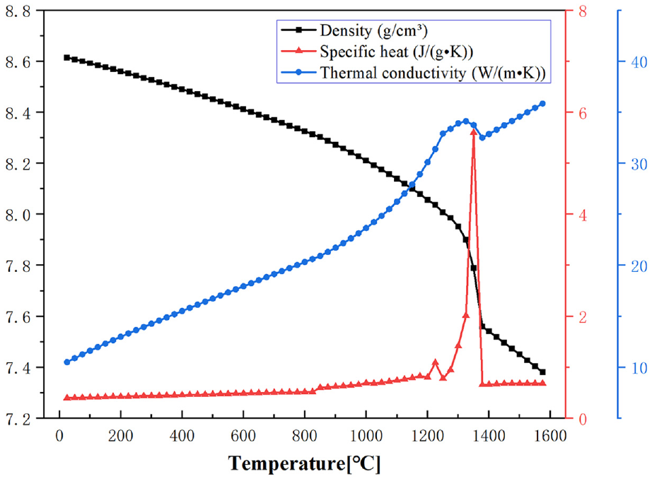
Thermal properties of DD5.
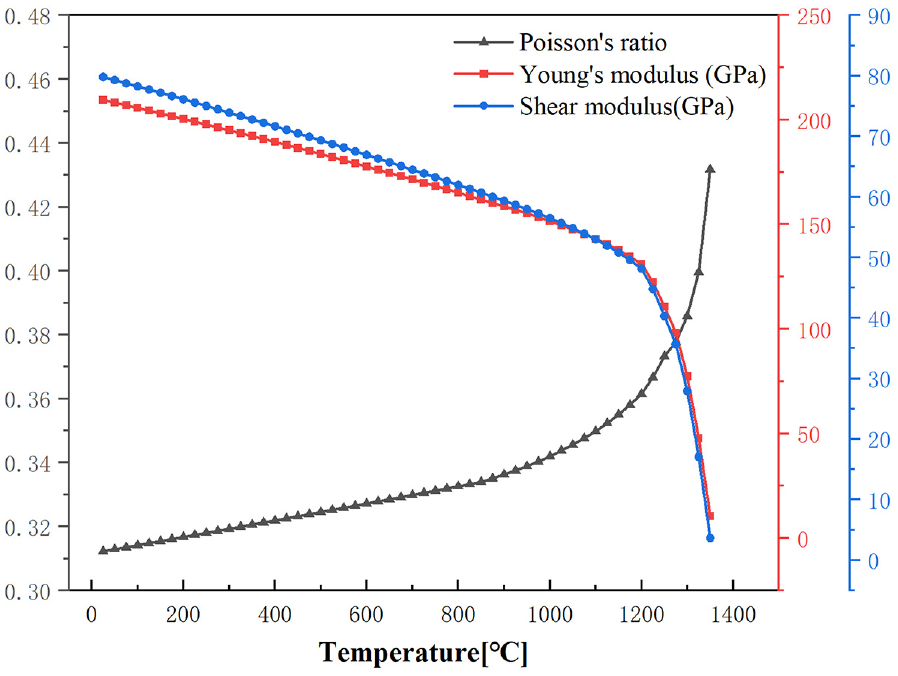
Mechanical properties of DD5.
Modeling parameters and methods
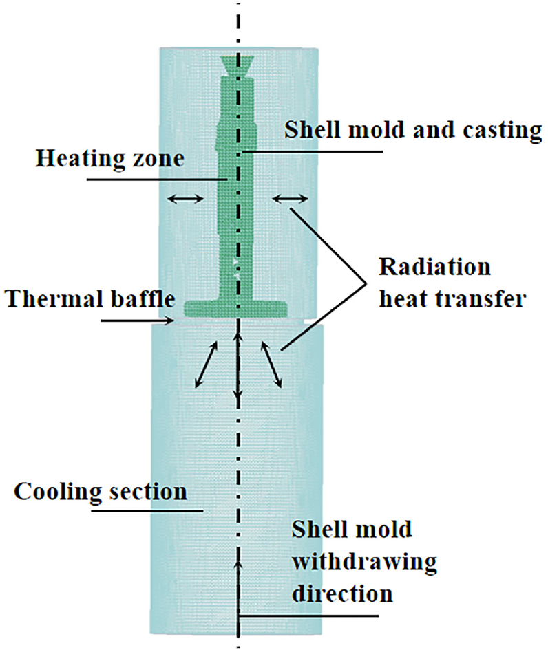
At present, the main methods of high-temperature turbine blade DS are HRS (high-rate solidification) and LMC (liquid metal cooling).24,25 The liquid metal-filled shell moves slowly from the heating zone to the cooling zone by a pulling motion. The alloy grows into single crystals or columnar crystals along a fixed direction under the vertical temperature gradient. Firstly, in the HRS process, the heat exchange between the alloy and the cooling zone of the DS furnace is radiative heat exchange. In the LMC process, the heat exchange between the alloy and the cooling zone is by convective conduction. Both perform radiative heat exchange in the heating zone. Based on the design principles related to single-crystal extraction, a single blade model with a spiral crystal selector and gating system for single-crystal blades were selected. The investment casting process is simulated with the finite element method (FEM). The mesh model of the DS system is shown in Figure 7. The simulation of hollow blades during the LMC process was performed to establish the relationship between the process parameters and displacement field. The mechanism of LMC, as shown in Figure 8, a heating furnace, radiation baffles, a chill copper plate, and a chilling zone are included. Modeling of the blades solidification processes required confirming the boundary conditions, which reflected the actual heat transfer process. Initial conditions are as follows: (1) Casting alloy temperature 1470°C, (2) Chill copper plate 25°C, (3) Shell preheating temperature 1500°C, (4) Heat emissivity for furnace 0.8 w/m2k. The heat transfer coefficient of the interface as is explained in Qiu et al. 9 For the process conditions, five different withdrawal rates, 3–7 mm/min, and four different pouring temperatures, 1470°C, 1490°C, 1510°C, 1530°C were performed. The mushy zone and displacement field were all calculated for each simulation.
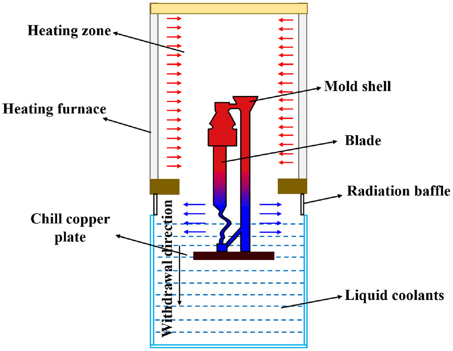
Schematic illustration of LMC directional furnace.
The mesh model of the directional solidification (DS) system.
Deformation prediction in investment casting
Simulation of the wax pattern of turbine blade
Wax pattern dimensional deflections account for 10%–70% of the dimensional deflection of final castings, and warpage deformation is one of the common quality defects in the molded products process.26,27 Numerous factors can cause the warpage deformation during the solidification, including the structure, materials, and the injection parameters. Deformation laws and calculation models during the wax pattern injection stage lay the foundation for the realization of near-net-shape investment casting. It has been reported that the injection parameters play an important role in the accuracy of the wax patterns and the experimental study examines the influence of injection parameters on the shrinking of crucial dimensions.28,29 As shown in Figure 1, the turbine blade has a complex curved structure with an internal cavity structure. The filling process directly determines the wax pattern’s surface quality and dimensional accuracy. Figures 9 and 10 show the filling process of the ceramic core and the blade wax pattern, reflecting the filling state of the wax material in the cavity. The entire filling process of the ceramic core and blade took 2.235 and 4.005 s, respectively. The wax material first filled the rabbet head of the blade and then advanced from the rabbet head to the blade body until it was filled, the filling speed was uniform, the feed was smooth, and there was no short shot retention phenomenon.
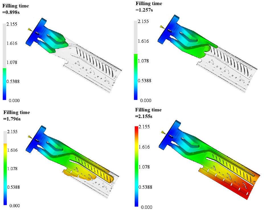
The filling process of ceramic core.
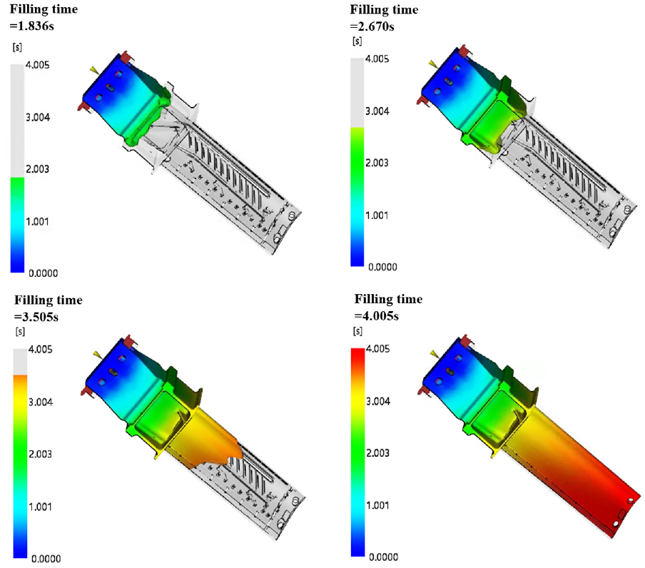
The filling process of the turbine blade.
Owing to the inherent material shrinkage properties of wax and the complex geometry of turbine blades, the deformation of the blade presents a complex nonlinear distribution.30,31 As the wax material is a poor conductor of heat, the larger the wall thickness, the severer the shrinkage of the wax pattern. As shown in Figure 11, the maximum warpage and deformation of the ceramic core is 0.1939mm and the average volume shrinkage reached 3.224%. As shown in Figure 12, the warpage deformation of the rabbet and blade tail is large, the most severe place reached 4.794mm, and the average volume shrinkage of the rabbet reached 5.416%. That is why warpage deformation is an important factor affecting the dimensional accuracy of the turbine blade wax pattern.
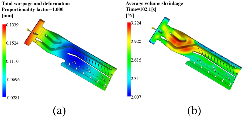
Ceramic core: (a) total warpage deformation and (b) average volume shrinkage.
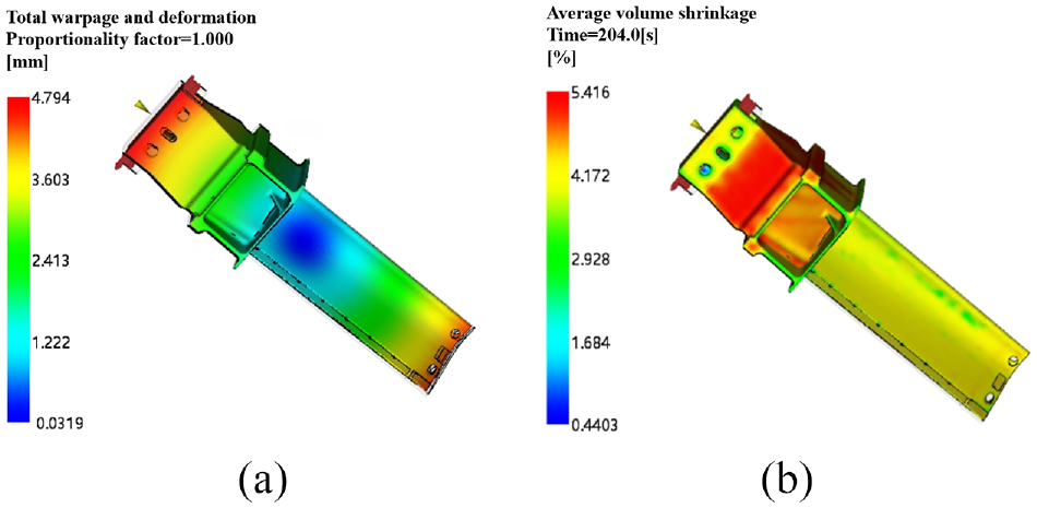
Wax pattern: (a) total warpage deformation and (b) average volume shrinkage.
Simulation of core deflection
Core deflection is one of the most common problems in the injection stage, especially in thin-walled turbine blades, where core deflection can lead to uneven wall thickness, warpage deformation, and other defects. 32 During the injection process, the melt flows forward in the cavity overcoming the filling resistance and there is a pressure gradient in the flow path. When the pressure gradient forms a large pressure difference around the core, core deflection may occur. The core deflection increases the uneven flow of the surrounding melt, resulting in wall thickness deviation and affecting the final shape of the blade and its mechanical properties. If the core deflection is significant, the core may be permanently bent or fractured after a long production period, shortening the service life. Here a reasonable design solution coping with the above problems is brought about.
In the conventional design of ceramic cores, a fixed end is added to the inlet to prevent core deflection. Figure 13(a) shows the deflection of the core at one fixed end. The fixed end has zero deflection, while the deflection at the furthest end from the fixed end is the largest, at 0.0500 mm. This demonstrates that the presence of the fixed end is effective in reducing core deflection. Adding the other fixed end to the original design, the results of the core deflection of the two fixed ends are shown in Figure 13(b). The maximum deflection of 0.0482 mm is produced at the middle thin wall of the ceramic core, proving that the presence of the two fixed ends can eliminate the core deflection. And the middle core deflection is caused by the uneven cooling and shrinkage of the wax material during the flow filling and cooling process. During the dewaxing process, the ceramic core has high strength and plasticity, and the deformation will be restored by the melting of the wax material.
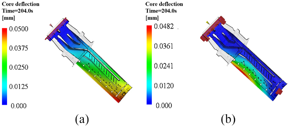
Core deflection (a) one fixed end (b) two fixed ends.
In addition, it is not only necessary to analyze the core deflection but also to ensure the overall low deformation of the wax pattern. Figure 14 shows the results of the deformation of the wax pattern with different fixed ends. The overall error analysis shows that the different types of fixed ends have little influence on the deformation of the outer surface of the wax pattern, only the deformation near the fixing point is caused by the fixing constraint.
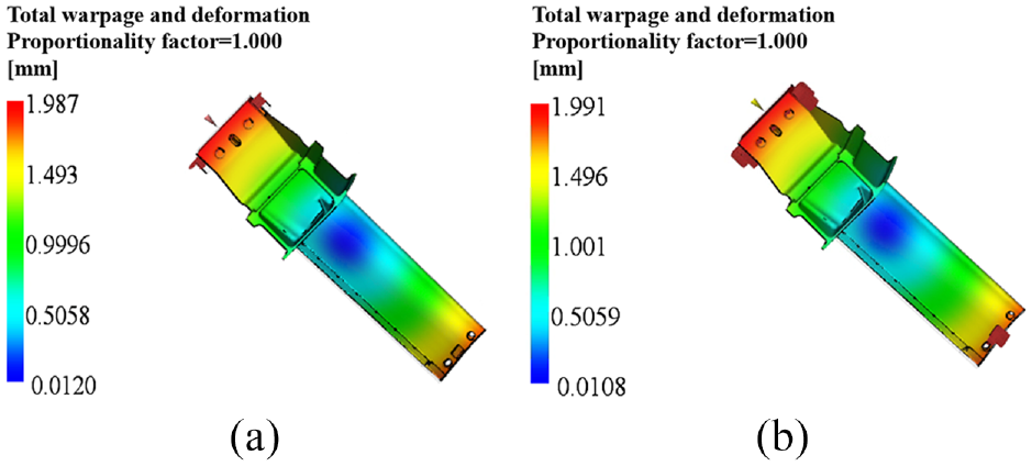
Total warpage and deformation: (a) one fixed end and (b) two fixed ends.
Simulation of directional solidification process
A multiscale three-dimensional(3D) turbine blade with a gating system model was established for simulating the fraction solid and displacement field. The solidification process simulation of the blade, as is vividly shown in Figure 15 from (a) to (d), the blade starts to solidify from bottom to top with the withdrawal rate and the distribution of the mushy zone can be observed in each part. The mushy zone is defined as the zone where the temperature is below the liquidus and above the solidus, which is from 1235°C to 1385°C for the DD5 superalloy used in this work. Several solid fractions, 52.6%, 54.2%, 58.4%, and 62.7% were chosen to present the changing tendency of the mushy zone. At the initial stage, the casting is affected by the chilling plate, cooling occurred quickly along the longitudinal direction. It is obvious that in Figure 15(a) the mushy zone has the smallest volume with the largest cooling rate, leading to the distance between both sides of the blade edge from the furnace chamber unequal. The mushy zone’s position of the near-wall side is slightly higher than the far-wall side. In Figure 15(b), the volume of the mushy zone shows a wider shape. With the decreasing of the cooling rate, the dendrite spacing becomes larger. In Figure 15(c), the semi-solidification area (yellow area) is expanding. The cooling speed of the blade edge is higher than the leading edge, inducing a larger radian of the thin wall’s edge, and the alloy solidifies primarily. In Figure 15(d), the area with the large cross-section begins to solidify.
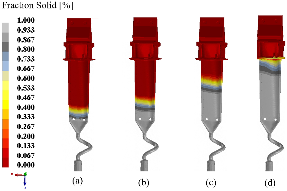
Solid fraction during solidification: (a) 52.6%, (b) 54.2%, (c) 58.4%, and (d) 62.7%.
Influence of pouring temperature on deformation
Considering that the high pouring temperature will lead to shell cracking and any other defects in actual production, appropriate process parameters should be selected for numerical simulation. Figure 16 shows the simulation results at different pouring temperatures of the displacement field with the same withdrawal rate of 6 mm/min.
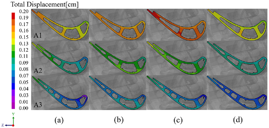
Total displacement at different pouring temperatures: (a) 1470°C, (b) 1490°C, (c) 1510°C, and (d) 1530°C.
Note that the design of a 3D turbine blade is commonly generated by stacking 2D sections. It is therefore reasonable to analyze the deformation of the turbine blade based on the 2D sections. To eliminate the effects of using 2D sections, the intercepted cross-sections were chosen with equal proportion, which means that the corresponding sections were not at the same height but had the same height proportional ratio relative to the XOY plane. With the increase in casting temperature, three representative A1, A2, and A3 cross-sections were taken to analyze the displacement of the blade. As can be seen from the overall cross-sectional diagram, the displacement of the A1 cross-section is the largest, and the displacement of the A3 cross-section is the smallest. Due to the characteristics of DS, the amount of displacement in the initial solidification section is the smallest. Thereafter, the deformation propagates with the withdrawal process. The maximum displacement reaches 0.2 cm at the A1 cross-section when the pouring temperature is 1510°C. With the increase of the pouring temperature, the amount of total displacement in the A1 section increases and then decreases. At 1510°C, the maximum displacement amount of the thin wall’s edge of the A2 section reaches 0.13 cm. The overall displacement distribution is uniform and less than 0.12 cm at 1530°C. The displacement amount in the A3 section becomes the largest when the pouring temperature reaches 1490°C. While the displacement of the leading edge of the A3 section becomes the smallest at 1470°C, which is 0.01 cm. It can be predicted that the displacement of the blade back is larger than the blade basin, and the displacement of the blade edge is larger than the leading edge. The total displacement amount of the section further away from the blade rabbet is much lesser, which agrees well with experimental results.
Influence of withdrawal rate on deformation for casting
According to the numerical simulation results, the displacement field under different withdrawal rates at the same pouring temperature of 1530°C is established and the maximum withdrawal rate is 7 mm/min, as shown in Figure 17. From a horizontal view, when the withdrawal rate is 7 mm/min, the displacement of the A1 cross-section is the largest which exceeds 0.12 cm. The displacement of the A2 cross-section showed a uniform trend in general and is not sensitive to the withdrawal rate during the process of solidification, and the deformation gradient between the blade basin and the blade back is not obvious. The deformation of the A3 cross-section is the smallest which does not exceed 0.09 cm. From a vertical view, the cross-sectional displacements vary more near the rabbet and less away from the rabbet, regardless of the withdrawal rate. Compared with the five groups of results, when the withdrawal rate is 5 mm/min, the total displacement of the A1, A2, and A3 cross-sections are all the smallest.
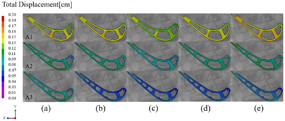
Total displacement at different withdrawal rates: (a) 3 mm/min, (b) 4 mm/min, (c) 5 mm/min, (d) 6 mm/min, and (e) 7 mm/min.
Experimental verification
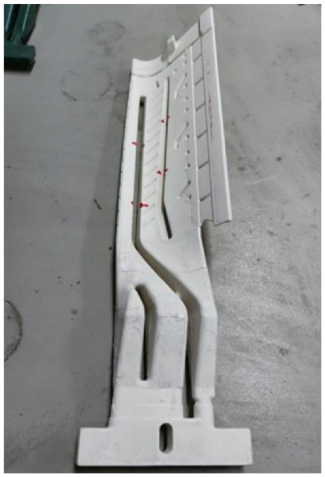
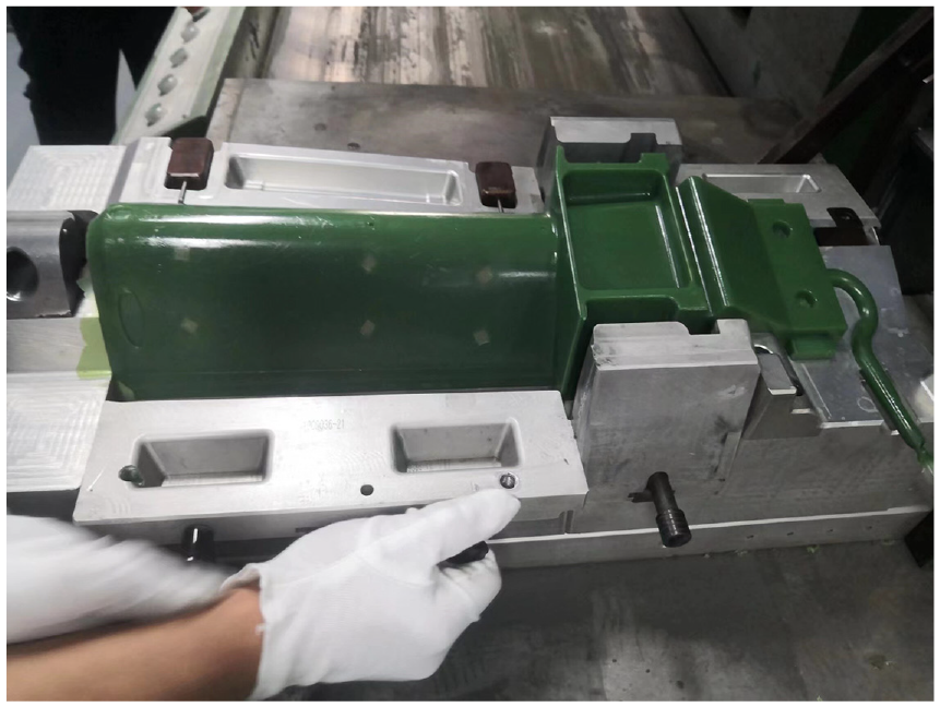
This paper realized a numerical simulation method coupled with experimental verification to determine the dimensional control of the wax pattern of ceramic core and blades, core deflection, and DS while considering the structural characteristics of thin-walled hollow turbine blades during the whole ICP. The ceramic core and wax pattern in actual production are shown in Figures 18 and 19. Since the wax pattern of the turbine blade has complex spatial surfaces and a thin-walled structure, the traditional measurement methods have large errors, and the appropriate digitizing method is used to collect the point cloud data of turbine blades. 32 In order to verify the accuracy level of the outer surface size of the turbine blade wax pattern, the point cloud of the turbine blade and the original model were compared in Geomagic Control software, and the 3D comparison results are shown in Figure 20, the dimensional deflection is between −0.2453 and 0.1540 mm. Furthermore, three sections were extracted and dispersed into 120 discrete points in accordance with the number of measurement points. All the Contour errors of wax pattern sections were within ±0.25 mm. As shown in Figure 21, it can be concluded that the deformation at the thicker part of the turbine blade is greater than that at the thinner part, the A3 section is far away from the wall thickness part, and the contour error fluctuation is the smallest, which is in great agreement with simulation results.
The ceramic core in actual production.
The real wax pattern of the turbine blade.
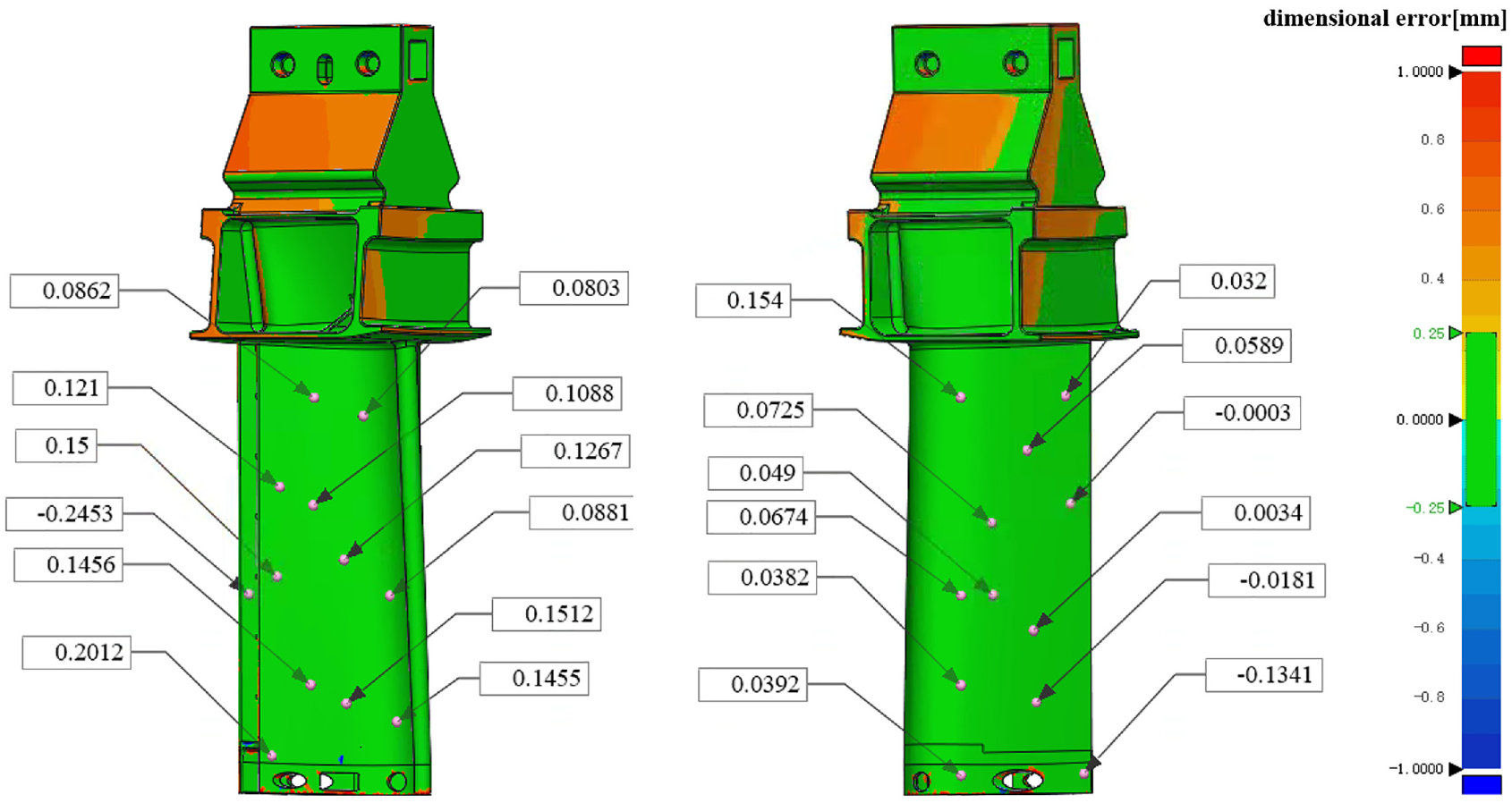
The Comparison and annotation results of wax pattern.
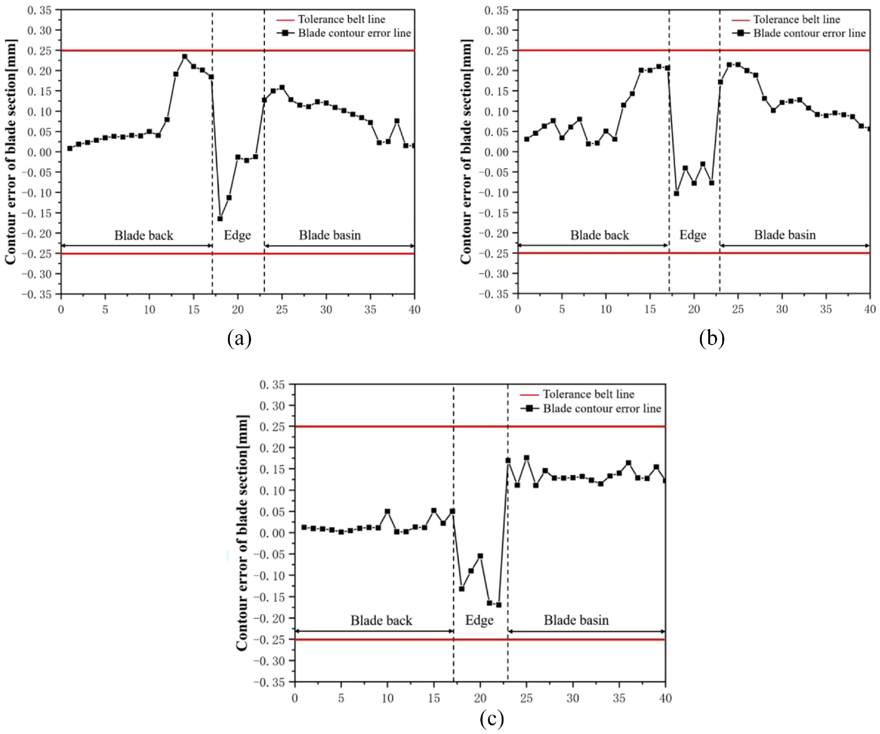
Contour error of wax pattern of the turbine blade: (a) A1 section, (b) A2 section, and (c) A3 section.
The DS process of large single-crystal blades was simulated, coupled with studying the displacement field and analyzing the influence of casting process parameters on dimensional accuracy. According to simulation results, three groups of the DS process parameters were selected for the experiment, the pouring temperature was 1530°C, 1510°C, and 1490°C, and withdrawal rates were 5 mm/min, and 6 mm/min, respectively. As shown in Figure 22, the results show that when the withdrawal rate is 5 mm/min, and the pouring temperature is 1530°C, the dimension error of the casting blade is the smallest. Furthermore, three sections were extracted and dispersed into 120 discrete points in accordance with the number of measurement points. As shown in Figure 23, all the contour errors of casting blade sections were within ±0.50 mm. The results further confirm that the contour error fluctuation of casting is larger than the wax pattern because of the propagation and accumulation of dimensional error, which proves the necessity to investigate and control the deformation of each stage during the whole ICP.
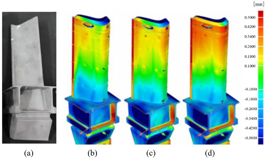
Experimental casting blade and 3D comparison results: (a) casting, (b) 1530°C, 5 mm/min, (c) 1510°C, 6 mm/min, and (d) 1490°C, 5 mm/min.
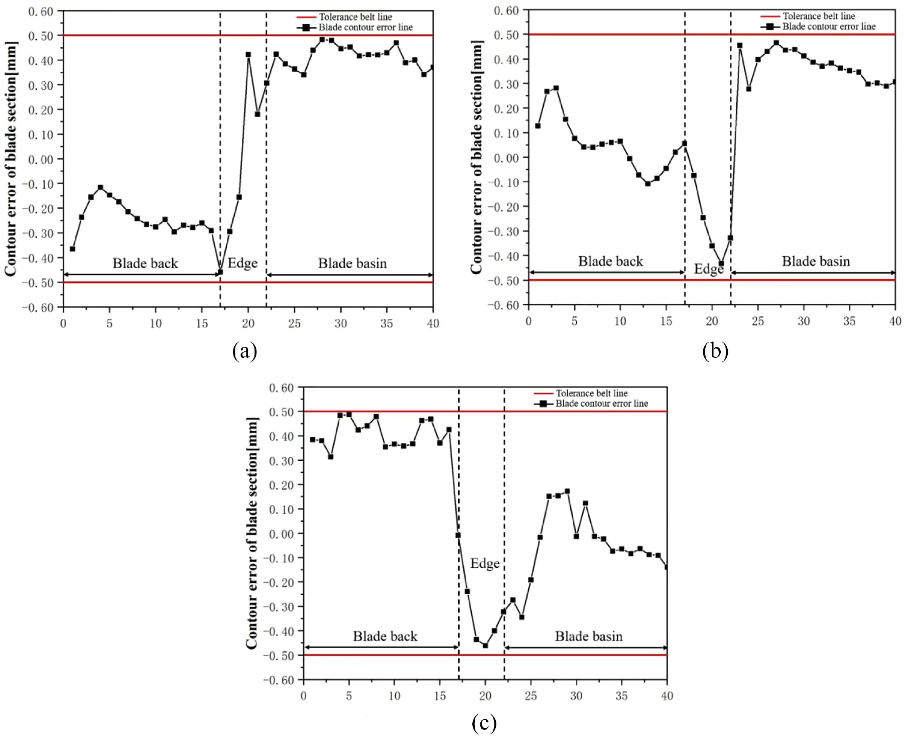
Contour error of turbine blade casting: (a) A1 section, (b) A2 section, and (c) A3 section.
Conclusions
This study investigated the nickel-based superalloy DD5 gas turbine blade and proposed a finite element model to predict the deformation of the wax pattern, core deflection, and displacement field of the DS process. The experimental results also prove the accuracy of the finite element model, which provides geometric guidance for the control of the dimensional accuracy of the turbine blade. The main results of this study can be summarized as follows:
Based on the previous studies of deformation, a numerical simulation method coupled with experimental verification was proposed to achieve better dimensional accuracy control from the ceramic core preparation to the DS process. The proposed finite element model can predict the deformation and improve dimensional accuracy of hollow turbine blades usefully, since the deformation accumulated during the investment casting process cannot be acquired directly. This is one of the novel contributions of this study.
The warpage deformation of the rabbet is significant during the wax injection stage, with the most severe area reaching 4.794 mm and the average volume shrinkage of the rabbet reaching 5.416%. A reasonable design solution of the two fixed ends we proposed can reduce the largest core deflection from 0.05 mm to 0.0482 mm, and the overall core deflection can be reduced obviously.
During the DS process, the displacement field of different process parameters were obtained by taking into account the structural characteristics of hollow turbine blades. It can be predicted that the displacement of the blade back is larger than the blade basin, and the displacement of the blade edge is larger than the leading edge. The total displacement amount of the section further away from the blade rabbet is much lesser. The influence of pouring temperature and withdrawal rates were studied, and the following optimum technological parameters were proposed: withdrawal rate of 5 mm/min and pouring temperature of 1530°C. The deformation analysis of different sections reveals that the manufactured turbine blades of optimum technological parameters meet dimensional accuracy requirements, and the simulation results are in agreement with the experimental results, which can decrease the experimental costs, and this is another novel contribution of this study.
A variety of parameters that influence the final casting blade throughout the ICP were examined, and the causes of deformation at each stage of the processes were explained. Due to technical limitations, we are unable to assess the mushy zone’s performance. It should also be pointed out that many other small processes in the whole ICP are supposed to be investigated, such as the deformability of an investment casting shell. Future work will include the investigation of the liquid-solid two-phase mushy zone’s performance of superalloy and the Elasto-Viscos-Plastic stress field calculation model, which can make the DS process simulation results more accurate. The authors also plan to build an integrated calculation software platform for the whole ICP to achieve better dimension accuracy of complex thin-walled castings, such as gas turbine blades.
Footnotes
Acknowledgements
This paper is the latest research. Neither the entire paper nor any part of its content has been published or has been accepted elsewhere. It is not being submitted to any other journal as well.
Declaration of conflicting interests
The author(s) declared no potential conflicts of interest with respect to the research, authorship, and/or publication of this article.
Funding
The author(s) disclosed receipt of the following financial support for the research, authorship, and/or publication of this article: This work was financially supported by the National Key Research and Development Program of China (2020YFB1710101, 2020YFB1710102), the National Science and Technology Major Projects of China (J2019-VI-0004-0117, 2017-VII-0008-0102), the National Natural Science Foundation of China (51821001, 52090042, 52074183), and Key Research and Development Program of Zhejiang (2020C01056, 2020C01062, 2021C01157). The Project was supported by fund of State Key Laboratory of Materials Processing and Die & Mould Technology (P2021-006), the fund of State Key Laboratory of Long-life High Temperature Materials (DECSKL202109), Shanghai Aerospace Science and Technology Innovation Fund.