
Abstract
Cutting-edge micro-geometry is a crucial factor influencing chip formation and tool performance. This paper investigates the effects of varying cutting edge radius (36–70 µm) on machinability and chip morphology during finish turning Ti6Al4V. An increase in edge radius decreases the cutting to thrust force ratio and produces lower chip thickness due to the increase in plowing zone depth. The machining temperature for the 48 and 52 µm edge radius tools is lower compared to all other tools. At the initial stage, the edge prepared tools exhibit larger flank wear, whereas subsequent flank wears progression is slower for the prepared tools as compared to the sharp tool. BUE and premature chipping is reduced for larger edge radius tool due to better edge stability provided by cutting edge preparation. Beyond the 59 µm edge radius, the process force, machining temperature, tool wear, and surface roughness increased steeply due to the increase in the size of the plowing zone. In addition to cutting force and machining temperature data, surface roughness, tool wear measurements and XRD analysis show that a radius range of 50–55 µm results in optimum performance for finish turning Ti6Al4V.
Introduction
The cutting tool’s macro-and micro-geometry significantly affects the specific cutting energy, 1 machining process, plastic deformation, shear, subsequent chip flow, process forces, tool wear, and surface finish. Modifying the material flow in the machining zone by changing the geometry can be used to alter the thermal, chemical, and tribological loads in the cutting zone positively. Ventura et al. 2 concluded that altering the micro-geometry through cutting edge preparation is one way of significantly improving the tool performance for a given cutting tool macro-geometry. By changing the edge micro-geometry, the thermo-mechanical load on the cutting edge can be altered to improve cutting edge stability, 3 reduce tool wear, 4 and improve tool life. 5 Fernández-Abia et al. 6 obtained lower process forces, surface roughness, and more uniform tool wear using prepared edge tools, which were further coated. Zhao et al. 7 optimized the edge radius for reduced tool wear and surface roughness when machining using CBN inserts.
Drag finishing, brushing, grinding, micro-blasting, abrasive flow machining, and magneto abrasive machining are the different edge preparation techniques used to alter the cutting-edge micro-geometry. Bouzakis et al. 8 used honing, and micro-blasting to produce edge radii in the range of 8–35 µm and showed that the wear behavior of PVD-coated carbide inserts could be improved. A higher edge radius was found to produce higher tool life. Bouzakis et al., 9 in an international cooperative effort, evaluated different edge preparation methods in the milling of Ti6Al4V and Inconel 718 (difficult-to-cut materials), hardened steel (42CrMo4), and stainless steel (304 L). The performance of the pre-treated (edge prepared) coated tool was significantly higher than the untreated (unprepared) coated tool; edge preparation yielded more benefits when machining Ti6Al4V and Inconel 718, whereas for hardened and stainless steel, the performance improvement observed was only marginal. A few unconventional approaches to cutting edge preparation have also been reported. Yussefian et al. 10 innovatively used electro-erosion edge honing and obtained edge radii with very low variability, thus demonstrating the repeatability of the process. Drag finishing has been the most commonly used method of conventional edge preparation techniques. Fulemova and Janda 11 found that tools prepared using drag finishing performed better than those prepared using grinding and lasers in terms of repeatability. Denkena and Biermann 12 conducted a comprehensive survey of the different methods used to prepare cutting edges. They concluded that drag finishing produced smooth and repeatable symmetric edge geometries, resulting in lower tool wear than other edge preparation methods.
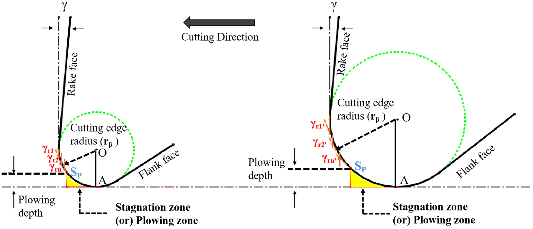
The effect of cutting edge radius on cutting forces, machining temperature, tool wear, chip formation, and surface integrity of machined parts on rough turning as well as the micro-turning process has been investigated comprehensively. Denkena et al. 13 found that cutting edge rounding significantly influenced material flow (chip formation), machining forces, and temperature. The chip formation occurs due to the plastic deformation of the material in front of the cutting edge, followed by the shearing action of the cutting edge as the chip is separated from the workpiece. For a perfectly sharp edge tool (zero-edge radius), the shearing takes place mainly along the primary and secondary deformation zone, as shown in Figure 1(a). As the cutting edge radius increases, the material in front of the cutting edge gets plastically deformed, and a part of it is pushed into the workpiece surface rather than being sheared along the primary shear zone, which is termed as the “plowing effect.” The plowing effect results in forming a tertiary deformation zone (also known as stagnation zone) in front of the cutting edge, as shown in Figure 1(b). The point (Sp) on the cutting edge, as shown in Figure 1(b), which separates the material flow into two modes – shearing and plowing – is known as the stagnation point (Sp). The separation or stagnation point on the cutting edge is an average of 30% of the cutting edge radius (rβ). 14 The depth of the plowing zone below the stagnation point depends upon the tool geometry and tool-chip contact mechanics. 15 The forces generated due to the burnishing of the material in the plowing zone by the tool’s flank face, widely known as parasitic or plowing forces, are not responsible for the chip formation. Denkena et al. 16 found that the process forces increase with the increase in the area of the normalized plowing zone. At a critical edge radius, the plowing forces dominate over the shearing forces.17,18 Laakso et al. 19 investigated the effect of tool edge geometry on plowing forces and reported that the plowing effect plays a vital role in the feed force in the turning process. With the increase in edge radius, mainly the thrust force (passive force) and feed force increase due to the dominance of the plowing of material in front of the cutting edge than the shearing action in the cutting zone. Wyen et al. 20 studied the consequence of cutting edge radius on surface integrity (residual stress, micro-hardness, surface roughness, and burr formation) during milling Ti6Al4V. They found that increased cutting edge radius increased the compressive residual stress as the plastically deformed material in front of the cutting edge was more significant for a higher edge radius. The effect of cutting edge radius on machinability and chip morphology during finish turning of Ti6Al4V alloy has not been studied.
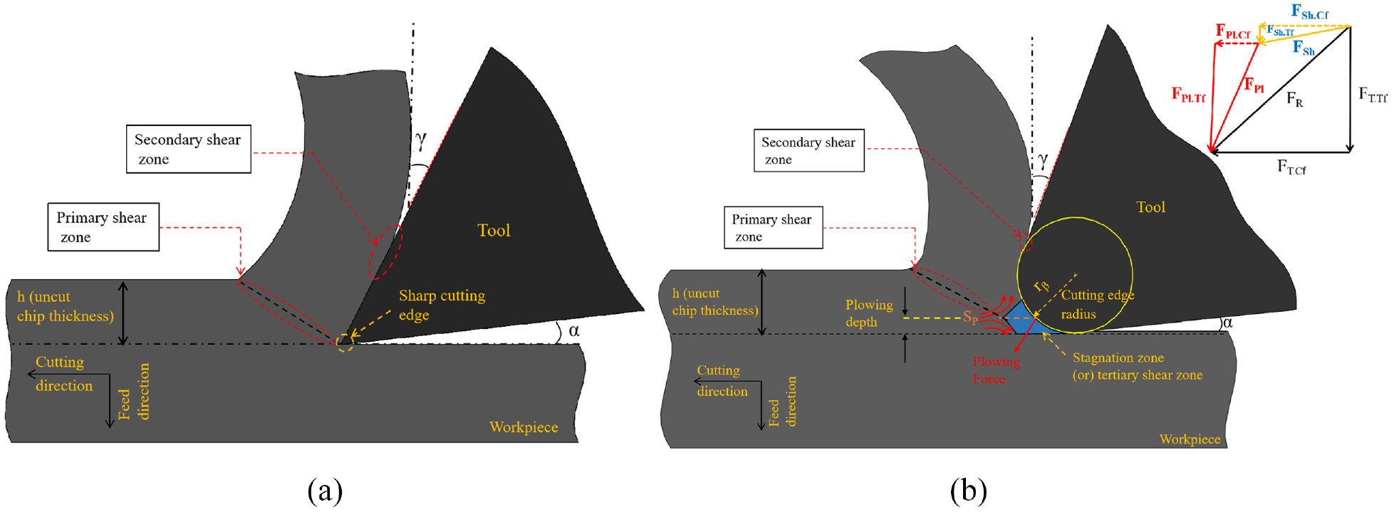
(a) Schematic representation of chip formation for sharp edge tool and (b) schematic representation of chip formation for rounded edge tool.
Drag finishing is used to prepare five different cutting edge radii (48, 52, 59, 65, and 70 µm). The effect of edge radius on the process forces, machining temperature, tool wear, machined surface roughness, surface integrity, and chip morphology in the finish turning of Ti6Al4V is studied. The coefficient of friction (µ) on tool-chip contact for different edge radius tools is determined using the extrapolation method. XRD analysis is carried out on the machined surface to confirm the experimental results.
Materials and methods
Workpiece material, cutting tools, and machining conditions
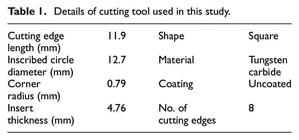
A standard SNMG 120408 insert with holder (WIDAX PSBNR2020K12) with a rake angle and relief angle of −6° and 15°, respectively was used in the finish turning experiments, and the insert details are given in Table 1. Turning experiments were conducted using an HMT semi-automatic lathe with a maximum rotational speed of 2000 rpm and a maximum spindle power of 7.5 kW. The machining parameters were: cutting speed – 110 m/min, feed – 0.2 mm/rev, and depth of cut – 0.1 mm. The machining parameters were chosen to delineate and study the effect of edge radius in macro-machining so that the tool-chip contact occurs predominantly on the curved/radius part of the cutting edge with the contact along the rake face kept to a minimum. Hence the influence of the rake angle/chip breaker on the rake face can be kept to a minimum and only the effect of edge radius can be studied.
Details of cutting tool used in this study.
Measurements
The tool was mounted on a Kistler 9257B multi-component dynamometer to measure the cutting forces and moments as shown in Figure 2. The dynamometer provided the three force components - feed force (Ff), radial force (Fr), and cutting force (FC). The thrust force (FT) during machining can be calculated from the resultant of feed force (Ff) and radial force (Fr). The average chip temperature when the chip exits the machining zone was measured using an infrared imaging camera (Flir T540 with a rated accuracy of ±2% within the temperature range measured). Tool wear was measured using a Nikon MM-200 measuring microscope, while workpiece surface roughness was measured using Surfcom 1500 SD3 surface roughness cum form tester at specific intervals. Flank wear was measured along the cutting edge from the rake face to the farthest point of wear on the flank face, and the maximum flank wear VBmax was reported.
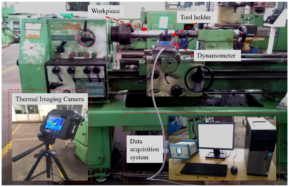
Experimental setup for this study.
Cutting edge characterization
The cutting edge micro-geometry has been characterized comprehensively using several parameters. Denkena et al. 21 and Padmakumar 22 used form factors to characterize the micro-geometry, while, Yussefian and Koshy 23 used contour parameters by fitting free-knot B-splines. However, the radius of the cutting edge is the most commonly used parameter for symmetrically honed edges, and optimizing this radius has been the most common approach to bring about improvements through micro-geometry variation.4,10,11,24–26 In this study, the cutting micro-geometry is characterized by cutting edge radius measurement. Cutting edge radius on the edge profile were measured using Zeiss Surfcom 1500 surface texture cum form measuring equipment. The new inserts had an initial edge radius ranging from 36 to 41 µm. Drag finishing was used to modify the edge radius in the range 48 µm ≤ rβ ≥ 70 µm. The radius measurements were made at five locations along the nose region of the cutting edge. The method suggested by Samuel Raj and Karunamoorthy 27 was used to determine the edge radius to avoid the uncertainty due to operator influence in the choice of the region for the circle as shown in Figure 3.
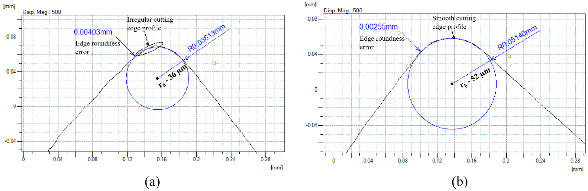
Characterization of cutting edge radius using form measuring machine: (a) edge radius 36 µm and (b) edge radius 52 µm.
Results and discussions
Effect of edge radius on coefficient of friction (µ)
A pilot study was conducted to determine the friction coefficient (µ) from the measured forces. The plowing components were eliminated from the process forces (cutting force, feed force, and radial force) by adapting the linear extrapolation method, 25 in which the process forces were extrapolated to zero uncut chip thickness (i.e. zero feed). The plowing component is separated from the measured force by drawing a best fit line for the experimental force results with respect to feed. This line is extended up to the zero feed (when uncut chip thickness is also zero) and the intercept of this line with the y-axis was used as the plowing component as shown in Figure 4 for cutting, radial, and feed force as shown in Figure 4(a)–(c). From Figure 4, it is seen that the plowing component of the measured forces is higher for the radial forces than for the cutting forces for larger edge radius tools. The same trend was observed by Li and Chang 28 that the feed force increases rapidly than the cutting force as the cutting edge radius increases. It implies that the increase in cutting edge radius influences the radial forces more than the cutting forces. For larger edge radius tools, the percentage contribution of the plowing component in the total radial and feed forces is more than that of the plowing component in the total cutting forces. The total cutting and thrust forces can be written as the sum of the corresponding plowing and shearing components using equations (1) and (2) as:

Where, FT.Cf = total cutting force or experimental cutting force; FPl.Cf = plowing component in cutting force; FSh.Cf = shearing component in cutting force.

Where, FT.Tf = total thrust force or experimental thrust force; FPl.Tf = plowing component in thrust force; FSh.Tf = shearing component in thrust force.
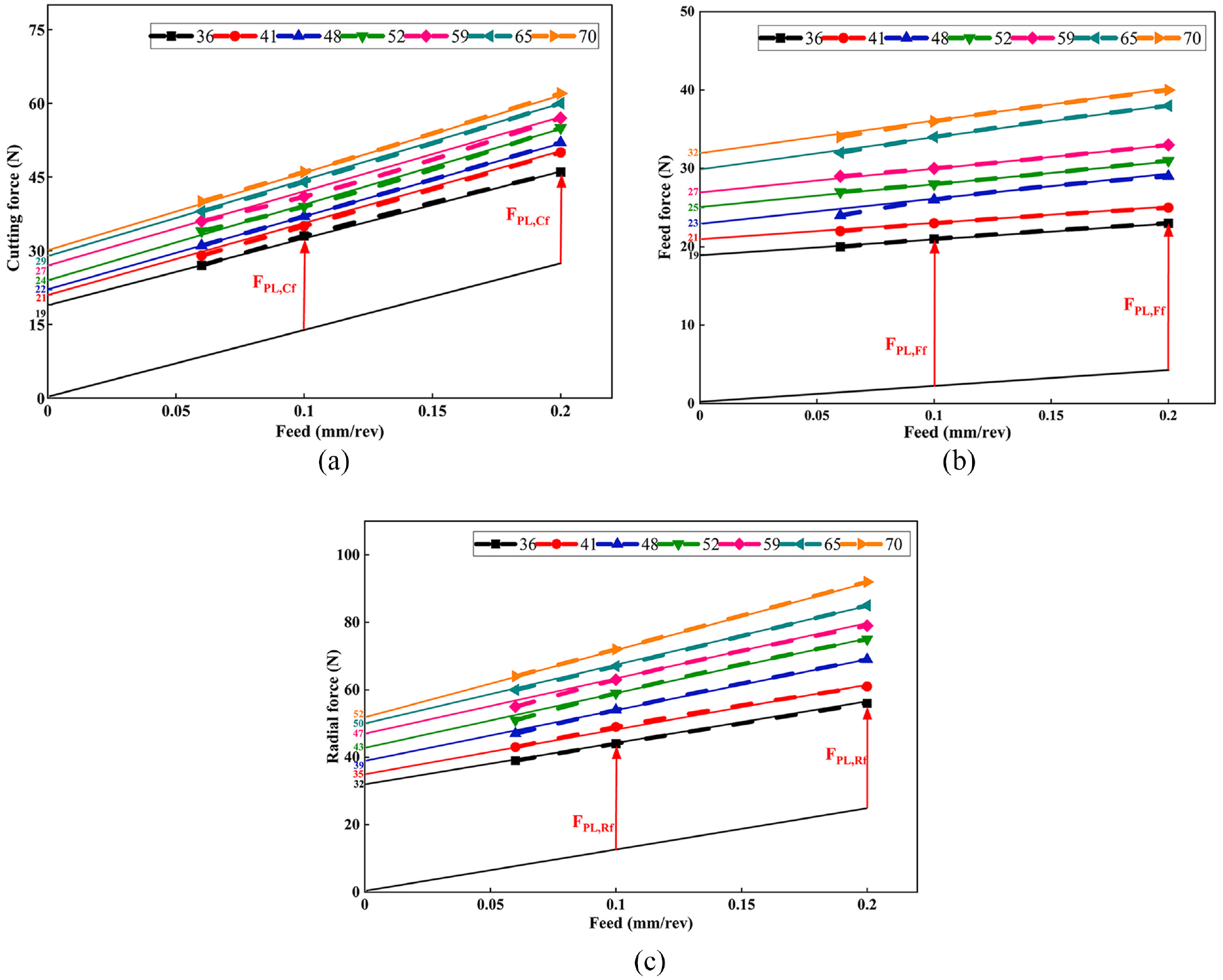
Plowing force components for different edge radii: (a) cutting force, (b) feed force, and (c) radial force.
The thrust force is the resultant of the feed and radial forces.

Where
The plowing component of thrust force is the resultant of the plowing components of the feed and radial forces. Hence

Where,
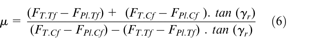
Tool-chip friction coefficient can be calculated from the equation given below, 29

In the above equation, γ is the nominal rake angle between the tool rake face and the workpiece. In this study, the tool-workpiece contact occurs only on the curved portion of the cutting edge. Therefore, the actual cutting rake angle (γr) will not equal the tool rake face’s nominal rake angle (γ). The actual cutting rake angle varies along the curved portion of the cutting edge from −90° at point A (near the flank side) to the nominal rake angle (γ) of the tool (on the rake face), as shown in Figure 5. In this study, the average effective rake angle (γr) of the edge radius is calculated using the CAD model of the tool. From the 2D profile of the cutting edge which consists of edge radius, rake and flank portion, the rake angle is measured in between h and hmin locations, with h being the uncut chip thickness and hmin being the minimum uncut chip thickness which was chosen as 30% of the cutting edge radius. 30 The region below hmin is assumed to be the plowing zone. Since the cutting rake angle continuously varies along the along the curved portion of the cutting edge radius (above the stagnation point) where contact occurs between these two points, the angle is measured at five different points that are equally spaced between h and hmin. The angles between the tangent line and a vertical line at that tangent point were measured at five different locations. The average of the five values is taken as the average effective rake angle (γr). The curved region below the stagnation point does not affect the shearing of the material. As the cutting edge radius increases, the average effective rake angle (γr) increases in the negative direction. Considering the average effective rake angle (γr) and plowing effect due to the cutting edge radius, equation (5) can be rewritten to determine the apparent coefficient of friction on the tool-workpiece contact region as
Average rake angle (γr) for unprepared and rounded edge tools.
The friction factor or coefficient of friction (µ) at the tool-chip interface increases with an increase in edge radius. The values for the coefficient of friction (µ) for different edge radii are given in Table 2. As the ratio of tool edge radius (rβ) to the uncut chip thickness increases with an increase in cutting edge radius (rβ), this leads to more material deformation in front of the cutting edge. Also, the negative rake angle effect and increase in tool-chip contact length along the curved edge increase the friction coefficient with an increase in edge radius. 31
Co-efficient of friction (µ) for different cutting edge radii (rβ).

Further experiments to comprehensively study the effect of edge radius on process forces, machining temperature, tool wear, surface roughness (Ra), surface integrity (XRD and micro-hardness), and chip morphology were carried out at a constant feed rate of 0.2 mm/rev. The effect of plowing depends significantly on the ratio of uncut chip thickness to edge radius 32 and is prominent only when the ratio varies between 0.5 and 5. 33 This study investigates the edge radius effect within the above range to study the effect of plowing on the machinability.
Effect of edge radius on process forces
Figure 6 shows that the thrust forces (Ft) are higher than the cutting forces (Fc) for all the tools. This higher thrust force compared to cutting force is because contact happens only along the nose region and curved edge portion of the cutting edge. The thrust force (Ft) is determined from the resultant radial force (Fr) and the feed force (Ff), and it is found that there is a steep increase in the radial force (Fr) which is the most sensitive to edge radius followed by feed force (Ff). The thrust force (Ft) for the 70 μm edge radius tool is approximately 66% higher than that for the unprepared (36 μm edge radius) tool, while the cutting force is only 35% higher. The maximum increase in thrust force for the larger edge radius tool compared to cutting force is because of the greater increase in feed and radial forces with an increase in edge radius due to the increase in plowing effect. The thrust force (Ft) gradually increases up to an edge radius of 59 μm, beyond which a drastic increase in thrust force (Ft) is observed. The increase of thrust force rate almost doubles beyond the edge radius of 52 μm because of the increased plowing effect, and these results agree with Rech et al. 34 and Zhao et al. 7 The ratio Fc/Ft being less than one is a trait of negative rake angle tools and has been found to increase with the increase in negative rake angle. 35 This ratio is also found to decrease with a decrease in the ratio of uncut chip thickness to edge radius. When the depth of cut is low and uncut chip thickness is comparable to the edge radius, plowing dominates shearing. 36 The force ratio decreases with an increase in the edge radius of the cutting tool. The decrease in force ratio is that the material under the curved portion of the edge in the plastic deformation zone will be larger due to increased tool-workpiece contact for a larger edge radius, increasing the thrust force in the cutting zone. Therefore, the contribution of thrust force to the resultant force increases with an increase in edge radius due to the increase in plowing effect with an increase in edge radius.
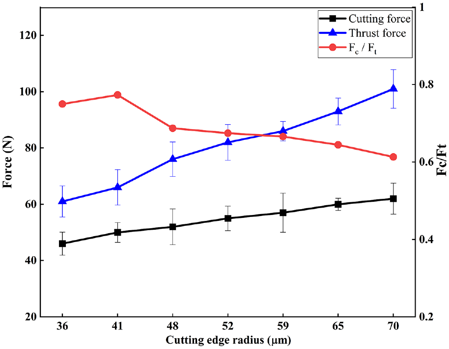
Effect of cutting edge radius on process forces.
Effect of edge radius on machining temperature
Figure 7(a)–(c) shows the thermal camera image for different edge radii and Figure 7(d) depicts the effect of edge radius in machining temperature. There is not much variation in chip temperature up to 52 µm radius even though the size of the plowing zone increases with edge radius because of the poor thermal conductivity of titanium. However, there is a steep increase in the chip temperature beyond a 59 µm radius because of the significantly larger plowing zone, which agrees with the force values. The increase in cutting edge radius increased the flow velocity of the material in the plowing zones, which led to a rise in machining temperature at the cutting zone (chip formation point on the rake face). 30 The minimum machining temperature for the 48 and 52 µm edge radius tool will be beneficial in increasing the cutting speed for the same tool life by selecting an optimum radius in the 50–55 µm. Yen et al. 37 suggested that the larger bulk of tool material available for conducting the heat generated in the case of larger radius inserts may be the reason behind reduced tool-chip interface temperature.
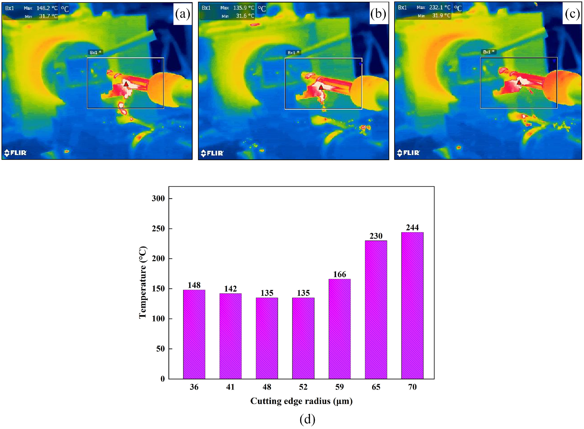
Thermal camera images for different edge radii: (a) edge radius 36 µm, (b) edge radius 52 µm, (c) edge radius 65 µm, and (d) effect of cutting edge radius on machining temperature.
Effect of edge radius on tool wear
Flank wear increases with time for all the tools (Figure 8) but is initially larger for higher edge radius tools. This is due to the larger area of contact of the workpiece with the tool flank face, which results in a greater plowing action for a larger radius and the possible increased elastic recovery of the workpiece along the tool flank face for a larger radius.21,38 However, as machining progresses, the sharper/unprepared edges undergo faster wear along the flank face due to mechanical and thermal stress concentration and consequent damage to the edges, which manifests as larger flank wear compared to higher edge radii – 48, 52, and 59 µm. The 65 and 70 µm edge radius tools undergo severe wear because the larger plowing region ahead of the cutting edge leads to higher forces. The severe flank wear for the larger edge radius tool (65 and 70 µm) can be observed from the flank wear images for the different cutting edge radius tools at the end of 60 min of machining in Figure 9.
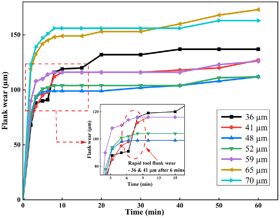
Flank wear (μm) progression with machining time (min).
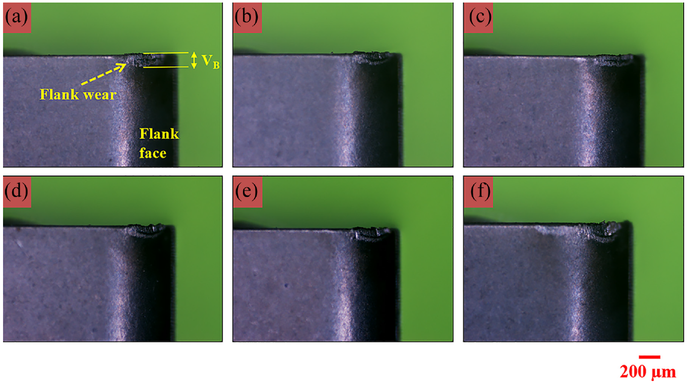
Flank wear images at the end of machining for various edge radii: (a) 36 µm, (b) 41 µm, (c) 48 µm, (d) 52 µm, (e) 59 µm, and (f) 65 µm.
The chip trace area measured on the rake face also shows a similar behavior as flank wear (initially smaller for unprepared edges). Figure 10 shows the crater wear images for the different cutting edge radius tools at the end of 60 min of machining. Crater wear affects the cutting edge stability and may result in sudden chipping or breaking of the tool. In contrast to the flank face, the tool’s rake face showed vast differences. The smaller edge radius tools started to chip and develop crater wear at a very early stage which worsened as the machining continued. Deposition of the workpiece material on the rake face was also witnessed very early in the machining. The adhesion of the workpiece on the rake face for the lower edge radius tool may be due to the higher temperature concentrated on the sharp edges than on the rake face of prepared tools. 21 The smaller chip flow angle combined with increased up-curl reduces the tool chip contact length for the lower edge radius tools, which increases the temperature and normal, and shear stresses on the cutting region/tool tip and causes aggravated and unfavorable wear on the rake face. The larger chip trace area observed in sharper edge radius tools (36 µm) compared to larger edge radius (59 µm tools), as shown in Figure 11, can be correlated to the thicker and stiffer chips rubbing and getting accumulated adjacent to the cutting region on the rake face. Even though micro-chipping and built-up edges occurred on the cutting edge in the case of a larger edge radius, the chipping did not propagate further, and the workpiece material deposition is restricted to a minimal area near the cutting edge. Drag finishing makes the cutting edge smoother and prevents chipping, improving the tool’s stability and life. However, the amount of chipping increased for a radius beyond 59 µm because of the larger plowing forces.
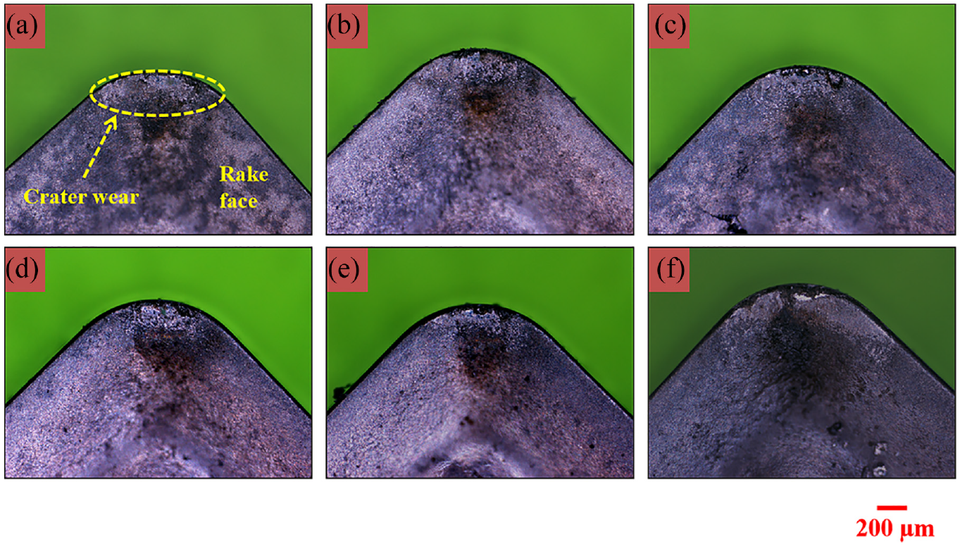
Crater wear images at the end of machining for various edge radii: (a) 36 µm, (b) 41 µm, (c) 48 µm, (d) 52 µm, (e) 59 µm, and (f) 65 µm.
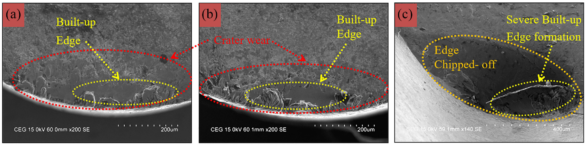
SEM image – Crater wear and BUE formation on tool rake surface for edge radius: (a) 36 µm, (b) 59 µm, and (c) 70 µm.
Effect of edge radius on surface roughness
The surface roughness (Ra) of the workpiece, in general, increases with the edge radius (Figure 12(a)). The surface roughness of the workpiece is proportional to the edge radius produced. A small area of metal gets stagnated (plowing zone) in front of the cutting edge and does not get cut but mostly dragged along with the tool (burnishing). Increasing the edge radius of the tool increases the plowing component compared to the shearing component, which consequently increases the deformation and associated elastic recovery. This may increase the workpiece’s surface roughness. 39 There is a slight improvement in surface finish for edge radius in the region of 52 µm due to the better material removal mechanism. For larger radii (>52 µm), the surface roughness of the workpiece increases with an increase in edge radius due to the increased severity associated with the plastic deformation, as evident from the larger plowing forces. However, unprepared edges show more irregularities compared to the prepared edges in the valleys of the lay produced on the machined surface (Figure 12(b)). This can be attributed to the increased chipping of the unprepared edges and lower microscopic irregularities on the cutting edge. The increased edge stability resulting from edge preparation is thus beneficial from the fatigue life point of view as the microscopic irregularities can serve as sites for crack origination. The large plowing force affects edge stability, chip formation, and workpiece surface quality for very large radii. These results differ from those obtained by Biermann and Terwey, 40 where lower roughness was observed for larger edge radius tools.
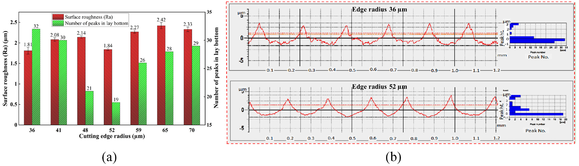
(a) Variation of surface roughness (Ra) and number of peaks in the lay bottom for different cutting edge radii and (b) comparison of surface texture for different cutting edge radius.
Effect of edge radius on surface integrity
XRD studies on the machined surface after 60 min of tool life show that the intensity and displacement of diffraction peaks were different for different edge radii. The XRD analysis was not performed on the machined surface produced by 48 and 70 µm as this tool’s performance was similar to the 52 and 65 µm edge radius tool, respectively. The XRD profile of the base material (Figure 13(a)) shows that the α-phase has preferred orientation along the (0 0 2) and (1 0 1) planes, while the β-phase has preferred orientation along the (1 1 0) plane. The α-peaks get broadened as a result of machining. The β-peak at (1 1 0) texture has almost disappeared after machining. Li et al. 41 suggested that this may be because of the β to α transformation or the submergence of these β-peaks in the neighboring broadened α-peaks. A magnified view of the diffraction range (2θ) from 38° to 44° is shown in Figure 13(b), as most of the changes are concentrated in this region. The broader peaks (higher peak width – FWHM – full width at half maximum) obtained for edge radii of 41, 59, and 65 µm than the base material as shown in Figure 13(b). This may be attributed to the increased plastic deformation during machining which causes micro strain as well as severe distortions in crystal lattice. 42 The width of the XRD peak for the 52 µm edge radius is slightly lower along with a leftward shift which shows that the material removal mechanism for this tool is significantly better than the other radii. The micro-hardness of subsurface varies from 326 to 341 HV for 36 µm edge radius to 70 µm edge radius as shown in Figure 13(c). The micro-hardness value is lower (318 HV) for 52 µm edge radius and higher (341 HV) for 70 µm edge radius tool. The plastic deformation zone for larger edge radius tools (beyond 65 µm) is larger due to the increased plowing effect. This induces strain-hardening phenomenon in the machined subsurface leading to increase in micro-hardness. 43 This can also be correlated to the broadened XRD peak of the machined surface obtained for larger edge radius (65 µm) tool.
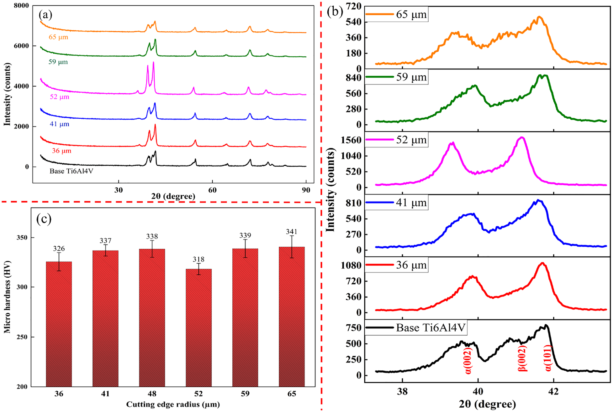
Effect of cutting edge radius on surface integrity: (a) XRD patterns for different edge radii, (b) Magnified view of XRD profile for the 2θ range 38–44°, and (c) variation of micro-hardness.
Effect of edge radius on chip thickness
The chip thickness was measured for several chips at different points along the chip length over different machining times, and the average chip thickness for each edge radius is shown in Figure 14(a). The chip thickness decreases with an increase in edge radius. For unprepared edge tools (36–41 µm), the chip produced was thicker, with the maximum chip thickness value in the range of 145–150 µm. The chip thickness for the edge radius of 48–65 µm varies from 125 to 130 µm, and for the 70 µm tool, the chip thickness value was ∼119 µm. The difference in chip thickness between the lower edge radius tool (36 µm) and the larger edge tool (70 µm) is nearly 30 µm. The marked reduction in chip thickness with an increase in edge radius is because of the difference in chip formation mechanism for sharp and rounded edge tools. In the case of a perfectly sharp edge tool, the entire volume of material (corresponding to the uncut chip thickness) in front of the cutting edge is plastically deformed and is separated as a serrated or segmented chip mainly because of the concentration of the plastic deformation in the narrow primary shear zone which undergoes adiabatic shear.
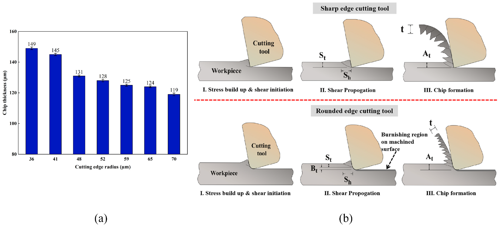
(a) Variation of chip thickness for different cutting edge radii and (b) mechanism of chip formation for sharp edge and rounded edge tools.
It can be seen in Figure 14(b) that for the sharp cutting edge, the primary shear zone initiates at the sharp cutting edge, and the segment thickness (St) is large and well pronounced. For a perfectly sharp tool, the actual uncut chip thickness (St) equals the theoretical uncut chip thickness (At). But the chip separation point for the rounded edge tool shifts along the cutting edge. The region below the separation point – that is, region Bt– is not removed but is subjected to burnishing by the tool’s flank. This burnishing depth – Bt, increases with an increase in edge radius. Thus, the individual chip segments attached are thinner than those for a perfectly sharp edge. In this case, the actual uncut chip thickness (St) is smaller than the theoretical uncut chip thickness (At). In the case of tools with an edge radius comparable to the uncut chip thickness, the point of chip segmentation (separation point) moves further up the rake face (Figure 14(b)). The St and Sh values for chips of larger edge radius are lower than those of sharper edge tools because of the shearing happening further up along the cutting edge and only the portion corresponding to St forming as a chip (7). The increase in the burnishing depth Bt is the reason behind the higher rate of increase in the thrust forces compared to cutting forces (as discussed previously) for the larger edge radius tool. This shows that plowing dominates shearing at such low feed rates and depth of cut in combination with the large edge radius and nose radius used in the study.
Increased stability of the cutting edge due to edge honing without a significant increase in friction coefficient at the tool-chip interface will be a major positive for titanium alloy finish machining by reducing the thermal stresses developed during machining and improving tool life. Further, experimental results can be optimized for obtaining the best input process parameter with respect to the prevailed MCDM techniques and soft computing techniques as reported in other studies.44–46
Conclusions
The effect of cutting edge radius on process forces, machining temperature, tool wear, surface roughness, surface integrity (XRD and micro-hardness), and chip morphology is investigated for finish machining of Ti6Al4V. The important findings are as follows:
The cutting forces are consistently smaller than radial forces, thus demonstrating the predominance of plowing over cutting, thus resulting in Fc/Ft < 1 for the chosen cutting conditions. An increase in edge radius is found to accentuate this behavior. The radial and feed forces increase rapidly for edge radius beyond 59 μm. The tools function in the realm of micro-cutting because of the relatively large edge radius and dominant curved surface area contact resulting in large plowing forces.
The machining temperature is lowered for the 48 and 52 µm edge radius tool, whereas the temperature on the machining zone increases steeply beyond the 59 µm edge radius tool due to an increase in the size of the plowing zone caused by the larger edge radius tool led to a rise in temperature on the machining zone.
The prepared tools exhibit larger flank wear initially (up to 5 min of machining time). However, the subsequent flank wear progression for the prepared edges is slower for tools with CER up to 59 µm. On the other hand, crater wear is consistently lower for the prepared edges. Further, the prepared tools also exhibit lesser BUE formation than the sharper unprepared tools, which also start chipping very early.
The edge stability improves as a result of edge preparation, thus preventing premature chipping and failure. The smooth edge topography results in a machined surface with reduced irregular tool marks in the lay for the tool up to 52 µm edge radius. For edge radius >52 µm, the surface roughness of the machined surface deteriorates due to severe plowing.
The reduction in chip thickness with an increase in edge radius is due to the increase in the plowing effect, which causes the chip separation point to shift up along the cutting edge, and the material below this point undergoes burnishing by the cutting edge.
From overall results, the tool edge radius range of 50–55 µm results in optimum performance for finish turning Ti6Al4V for the machining conditions; cutting speed – 110 m/min, feed – 0.2 mm/rev, and depth of cut – 0.1 mm. XRD and micro-hardness results also agree with these findings.
The authors intend to carryout Finite element analysis to study the effect of edge radius and varying process parameters on the machinability of Ti6Al4V and compare them with experimental results in the future.
Footnotes
Appendix
Declaration of conflicting interests
The author(s) declared no potential conflicts of interest with respect to the research, authorship, and/or publication of this article.
Funding
The author(s) disclosed receipt of the following financial support for the research, authorship, and/or publication of this article: Dr. D. Samuel Raj thanks SERB, DST, Government of India for funding this work under DST - Early Career Research award (File Number: ECR/2017/000893).