
Abstract
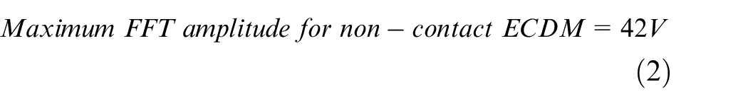
Electrochemical discharge machining (ECDM) is an emerging micromachining method to drill advanced non-conductive materials such as Hexagonal boron nitride (hBN). Physical contact of micro tools with work material could cause machining inaccuracies, excessive tool wear, and even tool breakage. In this study, a control system based on monitoring the force generated by the ECDM gas film has been developed to achieve non-contact machining of ECDM by dynamically adjusting the tool feed rate. The accuracy of the control system was verified by accelerometer and Fast Fourier Transformation (FFT) data. In the modules, it was found that a non-contact machining process requires the FFT amplitude to be lower than 42 V for a 1200 rpm tool rotation. The experimental results show consistent micro-holes with an average diameter of 650 µm and less than 20 µm error in the overcut achieved using this control system.
Introduction
Electrochemical discharge machining (ECDM is a non-traditional machining method that has been proven in drilling advanced non-conductive materials.1–5 With proper control of the tool feed rate, ECDM can be used in contact and non-contact mode between the tool and the workpiece. Several forms of feed rate control systems have been demonstrated in the literature.6–8 In the gravity-feed mechanism, a constant force is applied to the tool so that it is always in contact with the workpiece. 9 Another group of researchers showed that the gravity-feed system has an elastic deformation while machining based on the tool and workpiece locations; they proposed a new resistant feeding system to improve machining force conditions. 10 A similar pressurized feed ECDM was reported showing a possibility of deep hole machining with exerted pressure onto the workpiece. 11 Although simplistic in design, these methods prevent the gas film formation at the tooltip, consequently restricting the electrical discharges to only the sides of the tools. Hence, the material at the tooltip is removed mostly through mechanical drilling resulting in significant tool wear and machining inaccuracies. 12 Constant-feed ECDM is also studied showing that at the beginning of the machining process, the workpiece will not withstand any force (non-contact); however, while machining deeper into the hole, the process will become contact-mode with a higher exerted load on the workpiece.13,14 At higher feed rates in this method, it is hard to discern between ECDM and physical machining, so the tool material must be suited to withstand contact with the workpiece. 15 Linear feed control was also reported to improve the contact issues at a deeper hole by reducing the feed rate through the machining process. 6 Another method, termed adaptive feed, involves withdrawing the tool by a fixed distance when the tool-workpiece contact is detected by a load cell or switch.16,17 This temporary retraction allows a gas film to develop around the tool tip leading to a spark. Although this method minimizes the tool-workpiece contact, it does not eliminate it completely. Another study has utilized a similar retraction method to maintain a gap between the tool and the workpiece. 11 However, in that study, machining was continuously stopped so that the gap could be measured and recalibrated. More complex modules such as fuzzy interface system (FIC), were applied in ECDM control by measuring the voltage and current signals. However, this system required a circuit between the tool and a conducive workpiece.18,19 In this study, Hexagonal Boron Nitride (hBN) was used as the substrate. hBN is an electrically insulating and thermally conducting material with high melting and decomposition temperatures. Its chemical inertness leads to non-wettability with some molten materials. Although this method produces components with net/near-net shapes, it is difficult to adapt for features such as micro holes. Traditional drilling methods are not suitable due to the high hardness of hBN and excessive tool wear. This research work aims to achieve a pure non-contact mode of ECDM. A novel technique has been developed that utilizes the force exerted by the gas film to dynamically adjust the feed rate and achieve non-contact machining on hBN.
Experimentation
Experimental setup
The in-house built ECDM experimental setup is shown in Figure 1. A load cell and a current probe were connected to a data acquisition system (DAQ) to monitor the force and current signals. Precise Z-axis motion was provided by a stepper motor. The interface between the DAQ and the computer, as well as all control programing, was performed in LabView. A detailed view of the ECDM tank with workpiece arrangement is shown in Figure 2.
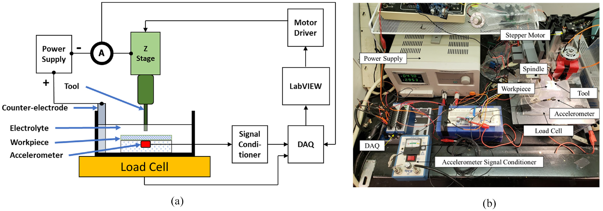
Experimental setup: (a) schematic and (b) physical setup.
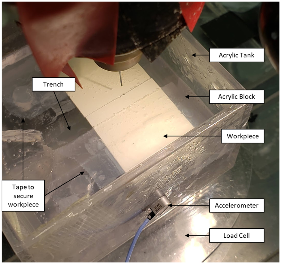
Detail view of ECDM tank and workpiece setup.
Determining the force applied by the gas-film
In ECDM, gas bubbles coalesce into a thin film. Electrical discharges through this gas film cause sparks. This layer of gas film exerts a force on the workpiece that can be measured using a sensitive load cell. When the tool approaches the workpiece, the gas film occupies the machined hole while the tool is still traveling downwards. Therefore, the compressed gas film causes a downward force on the workpiece. We propose that by continuously monitoring this force and maintaining it within a small range by varying the tool feed rate, a consistent gap can be maintained between the tool and the workpiece to avoid any physical contact between them. However, it should be noted that the force value measured by the load cell can be a combination of this gas-film pressure as well as the physical tool-workpiece contact. Thus, to identify the threshold value that could differentiate the gas film pressure from the force due to physical contact, a drill-and-hold experiment was performed with the parameters shown in Table 1.
Experimental parameters for ECDM.
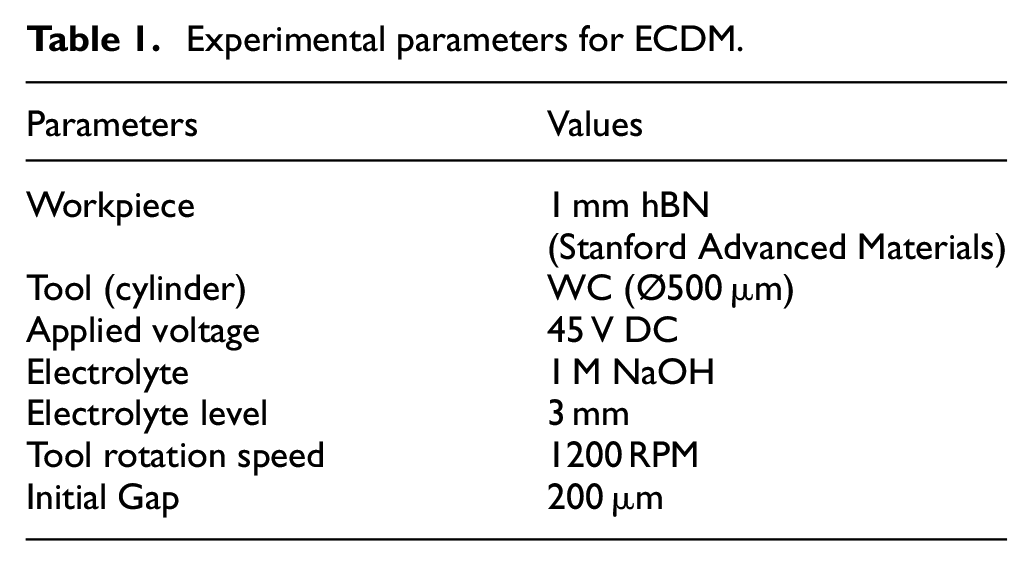
A tungsten carbide tool was moved at a constant feed rate of 15 µm/s from an initial gap of 200 µm above the sample surface to a depth of 500 µm beneath it, resulting in the substrate being machined for 300 µm. The initial 200 µm gap was set by moving the tool toward the sample at 1 µm/s until a load was detected, indicating that the tool had reached the sample surface. At this point, the tool was retracted 200 µm. After reaching this depth, the tool was held in place for some time while the load was measured. Holding the tool stationary ensured that any material in contact with the tool was machined away. Hence, the force measured by the load cell would be entirely due to the gas film. It was hypothesized that the load profiles resulting from this experiment could reveal the contact and non-contact mode ECDM, as shown schematically in Figure 3. During ECDM in contact mode, the peak load (represented by level 2) will occur due to additional force from shock waves caused by the sparking. As the tool is held stationary in this position and the material at contact is removed by the sparking, the physical contact ceases, and the load drops to level 3, which is the lingering force caused by the gas film pressure. The load profile obtained experimentally is shown in Figure 4.
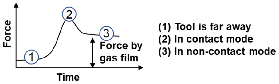
Schematic load profiles in ECDM drill and hold experiments.
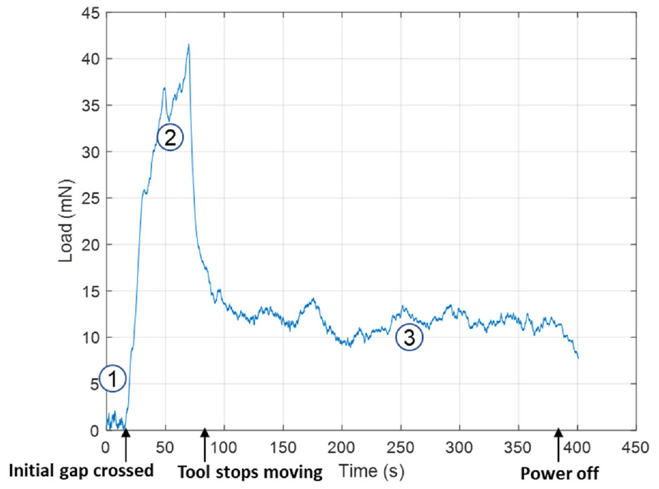
Load profile from ECDM drill-and-hold (6 µm/s) experiment.
From Figure 4, it is evident that the experimental load profile closely resembles the expected load profile. The observed tool-substrate contact force in region 2 is similar to the contact threshold force used in another study. 14 Additionally, the dissipation of the load after the power supply had been turned off further indicates that the lingering forces were caused by the gas film. Based on these results, the difference between the load exerted by the gas film and the initial load is shown in equation (1). The fluctuations in the peak profile are due to load variations caused by sparking in contact ECDM as well as physical drilling, while the fluctuations in the lingering profile are due to sparking in non-contact ECDM.

This average force exerted by the gas film force was used as a target input for the control system. However, it was evident from Figure 4 that the sparking causes the load to fluctuate to values higher than this average gas film force. Hence, a verification process was needed in conjunction with the load-based control system to make certain that there was no tool-workpiece contact.
Verification of non-contact using Fast Fourier Transforms (FFT)
An accelerometer was used to monitor the vibrations experienced by the workpiece. It was hypothesized that if the tool were rotating at a certain frequency and touched the workpiece, the accelerometer would pick up increased levels of vibrations at that frequency which would indicate contact. However, the accelerometer would also pick up vibrations at other frequencies from sources such as the stepper motor and ECDM sparking. To isolate the vibrations from the spinning tool, Fast Fourier Transforms (FFT) were performed. The amplitude spectrum graphs which indicate the level of vibrations were obtained at each frequency. Given that the tool rotated at 1200 rpm (i.e. 20 Hz), the FFT plots were condensed to observe the vibration amplitudes in only the 20 Hz region. FFTs are generally performed for short time intervals (1 s) so an FFT was performed for each second of the experiment. By observing the FFT peak amplitudes over the course of several drill-and-hold experiments, the maximum amplitude at which non-contact ECDM can be performed was obtained. For a tool rotating at 20 Hz, the FFT peak magnitudes for the drill-and-hold experiments are shown in Figure 5.
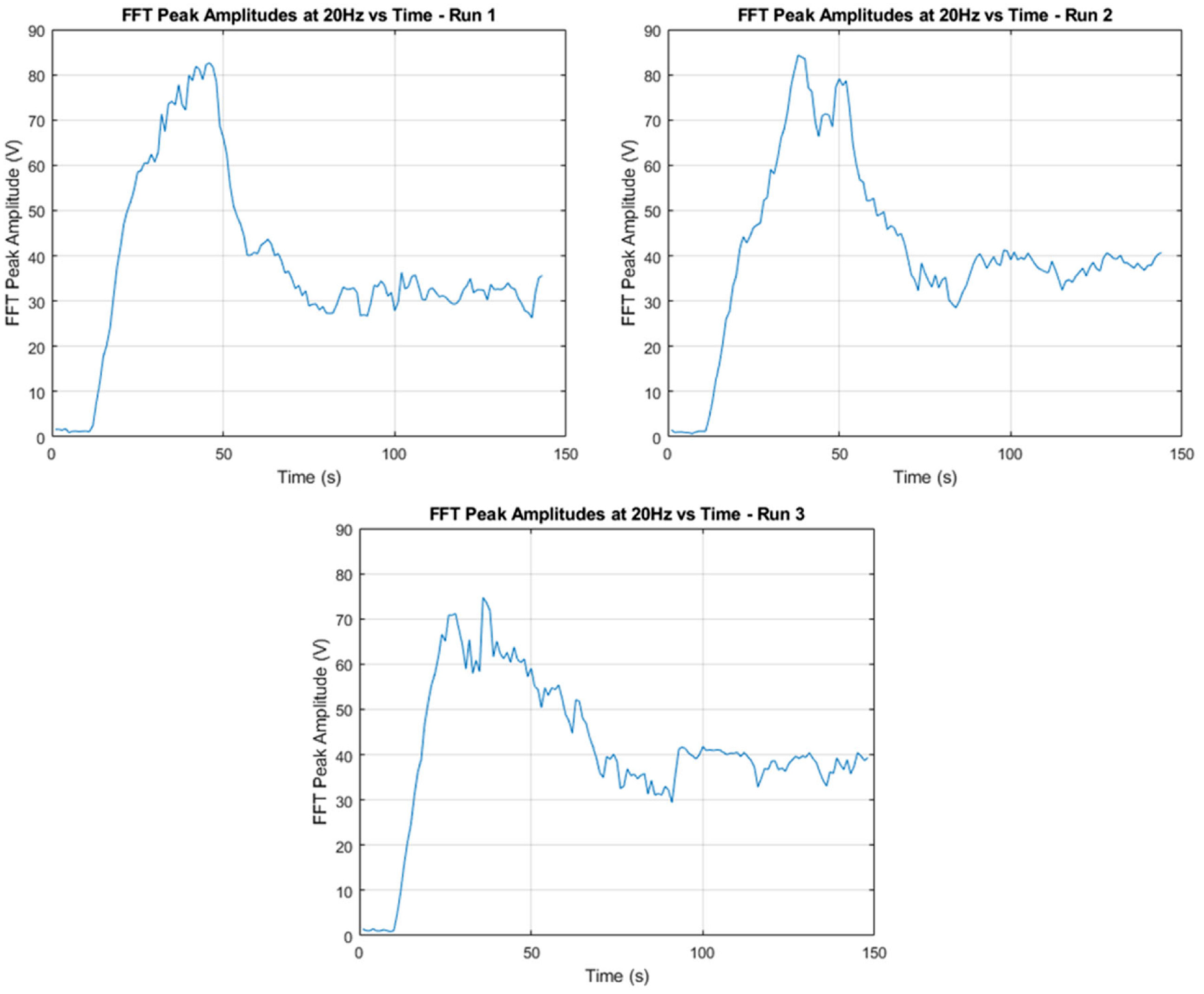
FFT peak amplitudes for ECDM drill-and-hold experiments.
As the tool enters the workpiece at a relatively high feed rate, its physical contact with the workpiece causes the FFT amplitude at 20 Hz to spike. Then, as the tool stops moving and any remaining material in contact is machined away, the FFT amplitudes settle at a value that is much lower than the prior spikes. This behavior is similar to that of the load cell but with fewer fluctuations since the gas bubbles do not affect the vibrations at the spindle frequency of 20 Hz. Over the course of these experiments, once the tool had stopped moving, the maximum FFT amplitude attained was 42 V. Therefore, to verify that there is no contact between the tool and the workpiece, the FFT amplitude should remain at or below 42 V.
Control scheme for non-contact ECDM
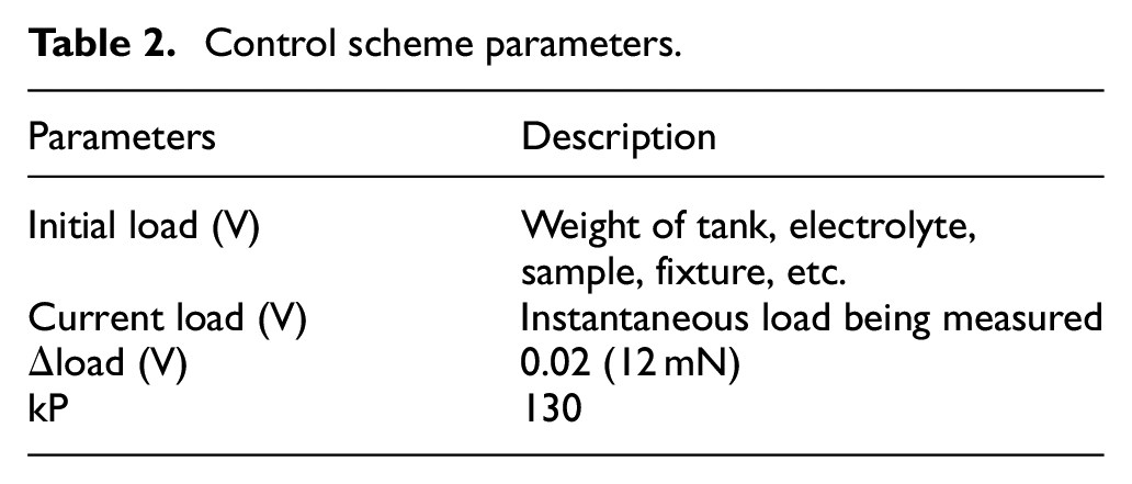
A closed-loop feedback system as shown in Figure 6 was implemented using LabVIEW that dynamically adjusted the feed rate of the tool based on the difference between the target load and instantaneous load. The initial load was measured before each experiment. The value from equation (1) was then added to it to determine the target load (equation (3)). A proportional controller, shown in equation (4), with a gain value (kP) of 130 was used to adjust the feed rate. The upper and lower limits for the feed rate were set at 6 and 1 µm/s, respectively. The feed rate is capped at 6 to avoid crashes caused by rapid changes beyond the processing speed of the control system. The lower limit was chosen because of hardware and software limitations.
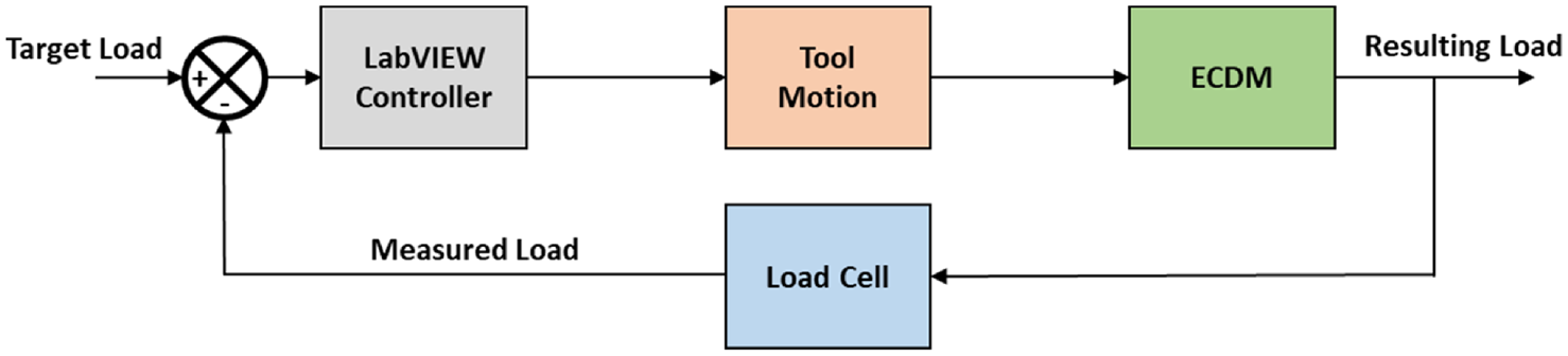
Closed-loop feedback control for non-contact ECDM.


Control scheme parameters.
Results and discussion
ECDM experiments were performed using the control system described in the previous sections and the parameters set in Table 2. Figure 7 shows the load variations over three through-hole experiments. As mentioned earlier, the load fluctuates over the course of an experiment. These fluctuations are caused by the continuous formation and collapse of the gas film. They were most prominent at the start of the experiment when the tool was traversing the initial gap of 200 µm. In this region, the gas bubbles inundate the entire tank causing large drops in the load. Once the tool starts moving deeper inside the workpiece, due to the dampening effect of the bubbles constrained inside the hole, the fluctuations gradually dissipate.
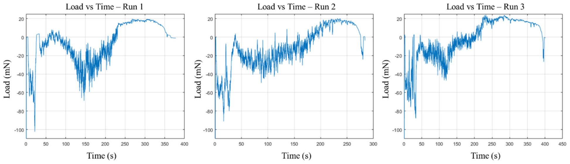
Force measurements in through hole experiments.
Figure 8 shows that the feed rate is dynamically adjusted to maintain the target load of 12 mN. As the depth of the tool increases, the load measurement also increases, causing the feed rate to automatically reduce until reaching the minimum set by the controller. The machined depth is shown in Figure 9. However, after reaching a certain depth, the minimum feed rate is not enough to compensate for the decrease in MRR, which causes the measured load to cross the target value. The load peak at values of 20, 20, and 24 mN for run 1, run 2, and run 3, respectively, then gradually reduce until the through holes are made. The reduction in MRR can be attributed to the reduced electrolyte circulation and debris removal at higher depths. 16
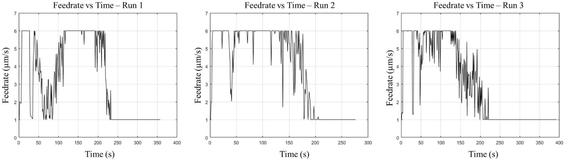
Experimental feed rates resulting from the control system.
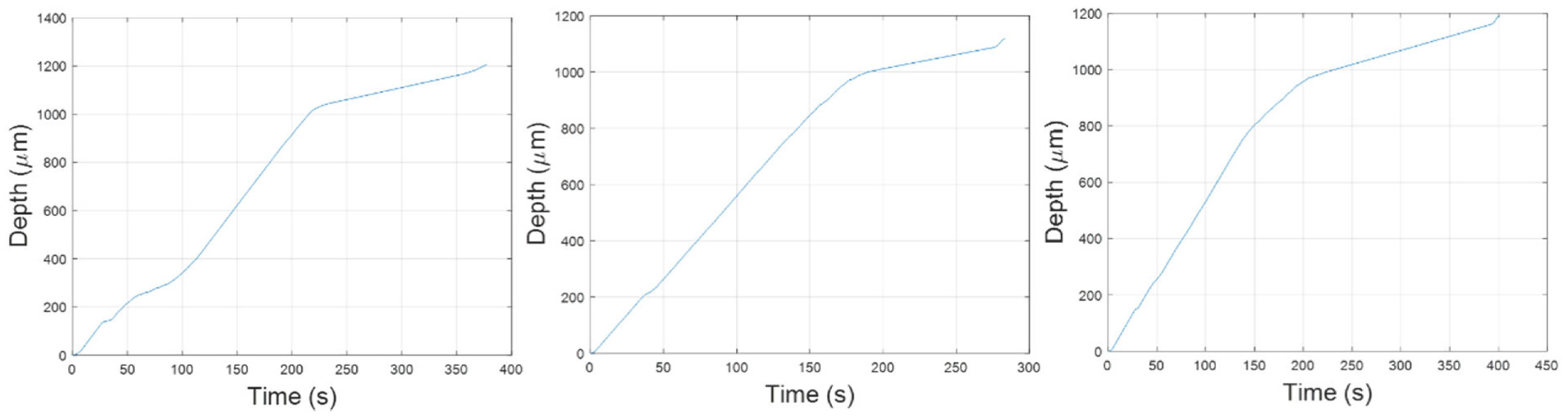
Experimental machined depth resulting from the control system.
Even though the peak loads were slightly higher than the target set by the controller, the results in Figure 10 show that the FFT peak amplitudes were consistently below the 42 V required to ensure non-contact. This confirms that the non-contact mode of ECDM was achieved in all three experiments. In fact, the highest amplitude attained was 30 V, suggesting that the target load could have been even higher than the value set for these experiments.
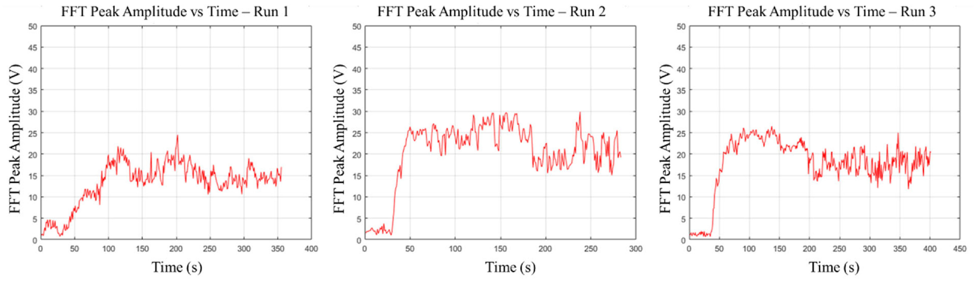
Experimental verification of non-contact using FFT amplitudes.
Samples machined with ECDM often experience undesirable side-effects such as inconsistent hole sizes due to exposure of the surface to prolonged discharges.20,21 One way to reduce the exposure is to increase the feed rate. With this control system, the exposure of the sample surface has been minimized, consequently minimizing the undesirable effects. The images of the holes produced by this control system are shown in Figure 11. Both the entry and exit holes exhibited consistent diameters of 660 and 640 µm, respectively, differing by only a few microns. The overcut is defined as the difference between the average of the entry and exit hole diameters, and the tool diameter. 20 In this study, the average overcutting was 149 µm. The difference in overcut between the three experiments was within 2 µm. The heat-affected zone was not visible on the entry side, while the exit side exhibited some minor damage. This was most likely caused by the lack of heat dissipation at higher depths due to reduced electrolyte circulation. 16
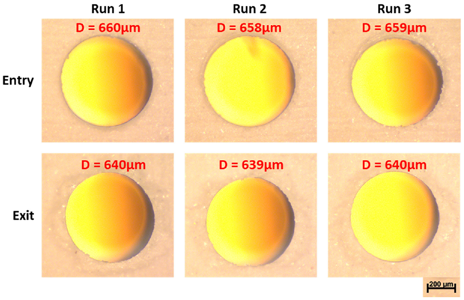
Entry and exit hole diameters for hBN samples machined using the ECDM control system.
Conclusions
A novel control system was developed that allows for non-contact micro-machining in ECDM. The average load exerted by the gas film was measured to be 12 mN using a sensitive lad cell. The closed-loop feedback control system used this target load to dynamically adjust the feed rate. Furthermore, verification of non-contact was performed using accelerometer data and Fast Fourier Transforms (FFT). The FFT result shows that the tool will remain in non-contact machining while the output voltage is below 42 V. The average overcut was 149 µm, and the difference in overcutting between each experiment was within 2 µm.
Footnotes
Declaration of conflicting interests
The author(s) declared no potential conflicts of interest with respect to the research, authorship, and/or publication of this article.
Funding
The author(s) disclosed receipt of the following financial support for the research, authorship, and/or publication of this article: This material is based upon work supported by the National Science Foundation [Grant No. CMMI-1833112]. Any opinions, findings, and conclusions or recommendations expressed in this material are those of the author(s) and do not necessarily reflect the views of the National Science Foundation.