
Abstract
In this study, the AA1050/Ti CP2 metallic multilayered composite was produced by accumulative roll bonding (ARB) using AA 1050 and commercially pure titanium Ti (CP-Ti ASTM grade 2) for three cycles at ambient temperature. The microstructure evolution was investigated by scanning electron microscopy (SEM) equipped with an energy dispersive spectrometer (EDS) and X-ray diffraction (XRD). Also, the tensile test and Vickers microhardness measurement were conducted to evaluate mechanical properties. The forming limit diagrams (FLD) were obtained for a metallic multilayered composite for the first time by the Nakazima test. It was observed that a continuous and well-bonded composite was fabricated after the first cycle. For the subsequent two cycles, necking and fracture of Ti reinforcement occurred in the Al matrix. The maximum tensile strength was reached after two cycles with almost a 98% increase compared to the annealed aluminum sample. However, the tensile strength was reduced after the third cycle. The uniform elongation considerably decreased after the first cycle and was maintained for the subsequent two cycles. The microhardness improved by 124% and 47% for Al and Ti, respectively, in the whole process of ARB in comparison with annealed Al and Ti. As a formability criterion, the level of forming limit curve (FLC) was reduced sharply after the first ARB cycle. For subsequent cycles, this reduction was neglectable. The Al/Ti composite fracture surfaces were a combination of shear ductile and brittle after the third pass.
Keywords
Highlights
This research aims to determine the forming limit diagrams of AA1050/Ti CP2 multilayered composite sheets for three cycles at room temperature for the first time.
The multilayered composite sheets were fabricated by the accumulative roll bonding method.
Also, the tensile test and microhardness measurement were conducted to evaluate mechanical properties.
The microstructure evolution was investigated by scanning electron microscopy (SEM) equipped with an energy dispersive spectrometer (EDS) and X-ray diffraction (XRD).
Introduction
Severe plastic deformation (SPD) processes apply considerable strain on materials to reduce grain size. These processes aim to produce ultrafine-grained (UFG) materials, which are well-known for their outstanding mechanical properties due to smaller grain sizes. In the long history of severe plastic deformation (SPD) processes, inventing new methods to reduce cost and obtain better results has always been noticed. Among SPD methods, accumulative roll bonding (ARB), high-pressure torsion (HPT), and equal channel angular pressing (ECAP) have received more attention. 1 The ARB has two significant benefits over other methods: (1) No need for expensive dies and forming machines and (2) high productivity. 2 Consequently, during the last decades, many researchers have spent considerable efforts to develop the ARB method.
A wide range of materials, including monolithic materials and metallic multilayered composites, have been fabricated by the ARB process. For monolithic materials, commercial-purity Ti, 3 1100 Al alloy, 4 and Mg-based AZ61 alloy 5 could be mentioned. For composite materials produced by ARB, various studies have investigated different aspects of this process in these materials. This trend was started by fabricating Al/Ni multilayer composite and studying its microstructure. 6 In addition to microstructure, mechanical properties and texture have also been studied for other bimetallic composites produced by this method.7,8 Apart from bimetallic composites, ceramic materials in combination with metals were fabricated by ARB.9–11 In this innovation, the homogenous distribution of ceramic particles in the metal matrix resulted in enhanced mechanical properties, including tensile strength and ductility. Mozaffari et al. 12 studied ARB combined with reaction annealing to obtain different intermetallic compounds to recognize appropriate annealing temperature for best mechanical properties. In addition to metallic multilayered composites and metal/ceramic composites, carbon nanotube (CNT) metal matrix composites were produced by ARB for dispersing CNTs into the metal and studying the effect of the process on these nanotubes. 13 It is worth mentioning that tri-metal composites, such as Al/Ni/Cu, 14 were also produced by ARB. Similar to bimetallic composites, uniform microstructure and improved mechanical properties were obtained. It has been reported that wear resistance, pitting corrosion resistance, and fatigue behavior can also be enhanced in various composites by utilizing the ARB process.15–17 In a novel method, warm accumulative roll bonding (WARB) was adopted to bring in desired microstructure with good mechanical properties for Al/WC and Al/Al2O3 metal matrix composites.18,19 A few attempts have also been made to produce hybrid nanocomposites, such as Al/WO3/SiC 20 and Al/ZrC/TiC, 21 with optimal microstructure and mechanical properties. More recently, the ARB method increased the fracture toughness of Al1050/Cu/MgAZ31ZB metallic multilayered composite. 22 In addition to the research mentioned above, for metallic multilayered composites, which is the case for the present study, a significant number of works have been conducted during recent years, including Zn/Sn, 23 Cu/Ni, 24 Cu/Zn, 25 Al/Cu, 26 Al/Mg, 27 Cu/Ti. 28 It should be noted that the majority of researches have been focused on microstructure and mechanical properties. It is not only true about ARB but also about cold roll bonding processes (CRB). 29 In comparison, there are a few works that have investigated the formability of monolithic metallic materials. For metallic multilayer composites, formability has not been studied before except few cases fabricated by methods other than ARB. For the Ti/Al composite produced by hot pressing, it was reported that the FLC of the composite lay between the FLCs of constituent metals. 30 In another research, 31 the formability of Ultrasonic Additive manufactured Al/Ti composites was investigated by biaxial hydraulic bulge tests at different temperatures, deformation rates, and sample orientations. From the stress-strain curves of the hydraulic bulge test, it was concluded that higher temperatures lead to lower stress and strain values. For the hot-rolled Al/Mg composite sheets, 32 the effect of temperature on FLC was examined by the hemispherical punch test. The results revealed that composite sheets exhibited better formability at higher temperatures. In metallic multilayered composites fabricated by SPD processes, specifically ARB, the formability behavior has not been investigated before. Since these materials have received attention for a wide range of applications, including automotive, large pipes, and pressure vessels, it is essential to devote some studies to formability.30,33 Besides, only a few studies have reported ARB production of composites by using Ti and Al alloy simultaneously. In a novel method, 34 asymmetric accumulative roll bonding (AARB) was employed for production. Accordingly, both more refined grain size and better mechanical properties were obtained through this method. By another research, 35 the formation mechanisms of TiAl3 in the ARB process were highlighted. In addition to these researches, the wear behavior of the composite was also studied, and no significant change was observed until the last cycle of the ARB process. 36
The most applicable criterion to predict metal sheets’ formability is forming limit diagram (FLD). 37 In this diagram, the major stresses are plotted against minor stresses in a wide range of deformation modes. The level of FLD specifies the maximum amounts of strains the sheet can withstand for a successful forming process. Various theoretical and experimental methods have been suggested in order to obtain FLDs. For example, a simulation-based approach 38 and a computational approach based on the Marciniak and Kuczynski theory 39 can be mentioned. Additionally, a combined numerical and experimental method has been proposed for obtaining FLDs at elevated temperatures. 40 For this research, the Nakazima test, one of the most common experimental methods, was selected. In this test, the initial samples are placed in a die and then are punched. Both sides of the curve are obtained by using different geometries for samples. 41
In this research, commercially pure aluminum alloy AA1050 and commercially pure titanium alloy Ti CP2 were used to produce a metallic multilayer composite by the ARB method. The present study aims to investigate the formability of such composites for the first time. Additionally, the microstructure and mechanical properties were examined comprehensively.
Experimental procedure
Materials
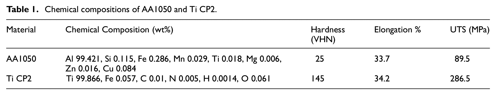
In this article, Al 1050 and commercially pure Ti (CP-Ti ASTM grade 2) were used as initial materials. The chemical composition of each material is given in Table 1. The initial samples were cut into 90 × 200 mm rectangular samples in the rolling direction. The thicknesses of Al and Ti strips were 1 and 0.5 mm, respectively. Al and Ti strips were also annealed at 385°C and 700°C for 75 and 60 min, respectively. The oxidation layer formed during annealing was removed by preparing samples for the ARB process, as is explained in the following.
Chemical compositions of AA1050 and Ti CP2.
ARB process
The initial strips’ bonding surfaces were degreased in an acetone bath to remove oxide and contaminated layer and then wire brushed by a circular stainless steel brush with a thickness of 0.1 mm. This stage was done in order to obtain a better connection between layers. In the next stage, two Al strips with one Ti strip in the middle were stacked and fastened by copper wires in the four corners to prevent slipping under the rollers. The initial thickness of the whole layers was 2.5 mm, constituted from 2 × 1 mm Al layer and single 0.5 mm Ti layer. The stack was rolled with a 50% reduction at ambient temperature without using lubricant. The effective thickness of the rolled stack was 1.25 mm. The explained process was assumed as the first cycle. Then the roll-bonded strip was cut into two-halves, stacked, and fastened by wires for the next cycle. The whole process was repeated for three cycles. Figure 1 shows the schematic illustration of the ARB process. An industrial rolling machine with a 400 mm rolling diameter at 15 rpm rolling speed with 30-ton rolling capacity was used.
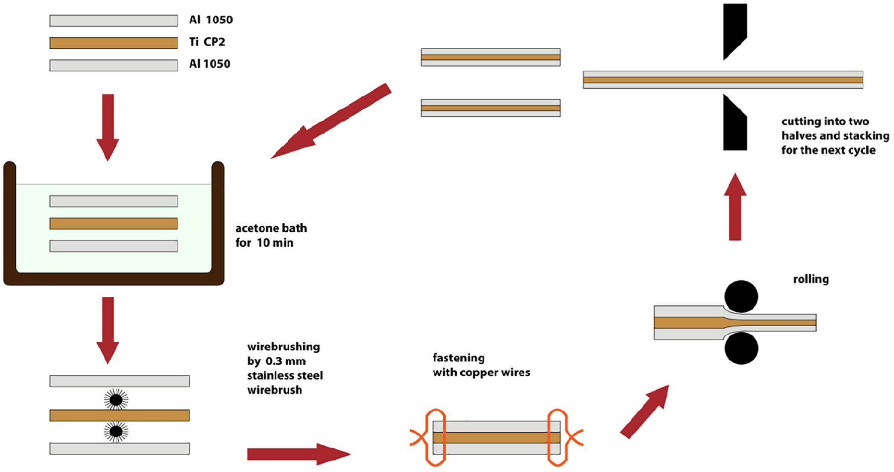
A schematic illustration of ARB for processing Al/Ti multilayered composite.
Microstructure
The composite microstructures were evaluated by field emission scanning electron microscope (FESEM), Mira3 Tescan model, equipped by an energy dispersive spectroscopy (EDS). The observations were done in the RD-ND plane. Before, the initial samples were mounted, sandpapered and polished. Then, the EDS line scan analysis was used to obtain a composition profile across the interface of Al and Ti. Also, composite phases were identified by an X-ray diffractometer operating at 40 kV and 30 mA with Cu K(α) radiations. The number of steps was 200, with a step size of 0.015°.
Mechanical properties
The Vickers microhardness of Al and Ti layers were measured separately on the RD-ND plane, using a load of 0.5 N and a duration of 15 s by a Shobsari M5 apparatus. Figure 2 shows the indentations for microhardness measurement. A total number of three indentations was used for each layer, and the average value was reported to minimize the error. Tensile test specimens were cut from ARBed sheets with orientation along the rolling direction, according to the ASTM E8M standard, using a wire-cut machine, showed in Figure 3. The width and a gauge length of the specimens were 6 and 25 mm, respectively. Tensile tests were conducted using a SANTAM STM-50 tensile testing machine with a 0.05 mm/s crosshead speed at room temperature. To get accurate results, two tensile test experiments were done for each cycle of ARBed samples. After that, to evaluate the fracture mode of specimens, the fracture surfaces were observed by SEM.
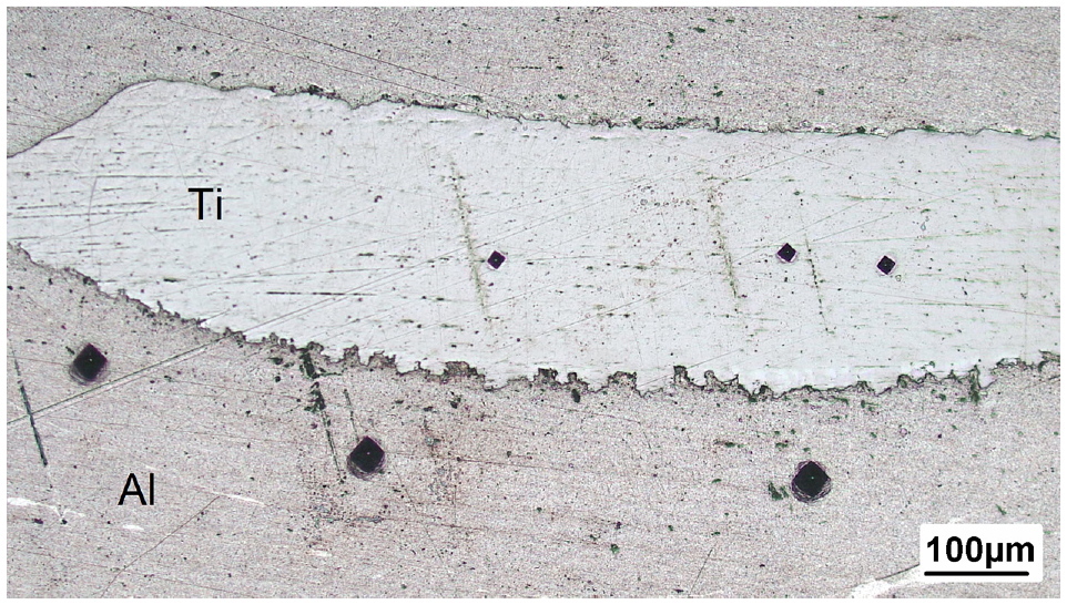
Micrograph of the areas for microhardness measurement in each layer.
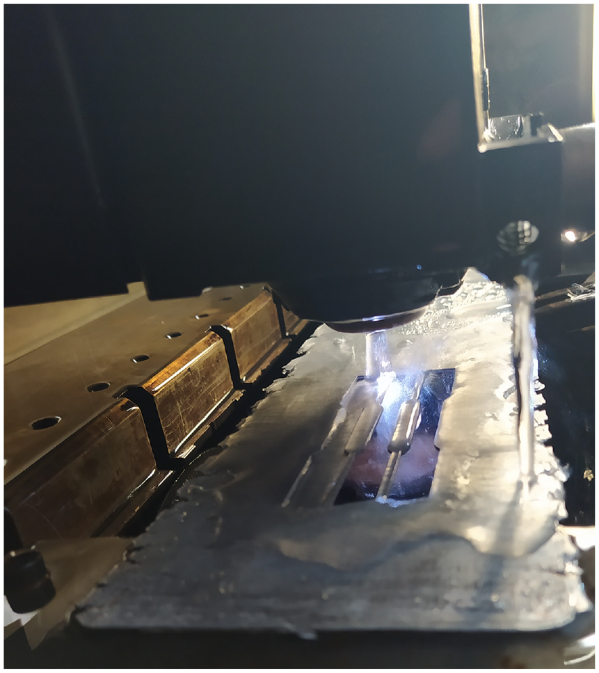
Wire-cut process for cutting tensile test specimens.
Experimental determination of forming limit diagrams
The Nakazima test was employed to obtain FLDs, using biaxial stretch forming. 12 This test consists of a die for inserting sheets on it and a hemispherical punch. Due to limitations of the ARB process, including edge cracks produced after each cycle, using ISO 12004 standard dimensions was not possible. Therefore, a scale-down die, equivalent to one-fourth dimension of the standard die, was used. 13 A wire-cut machine cut the initial samples with different widths. Afterward, circular grids were marked on the samples using an electrochemical marking machine. Figure 4(a) shows samples after the wire-cut and marking process.
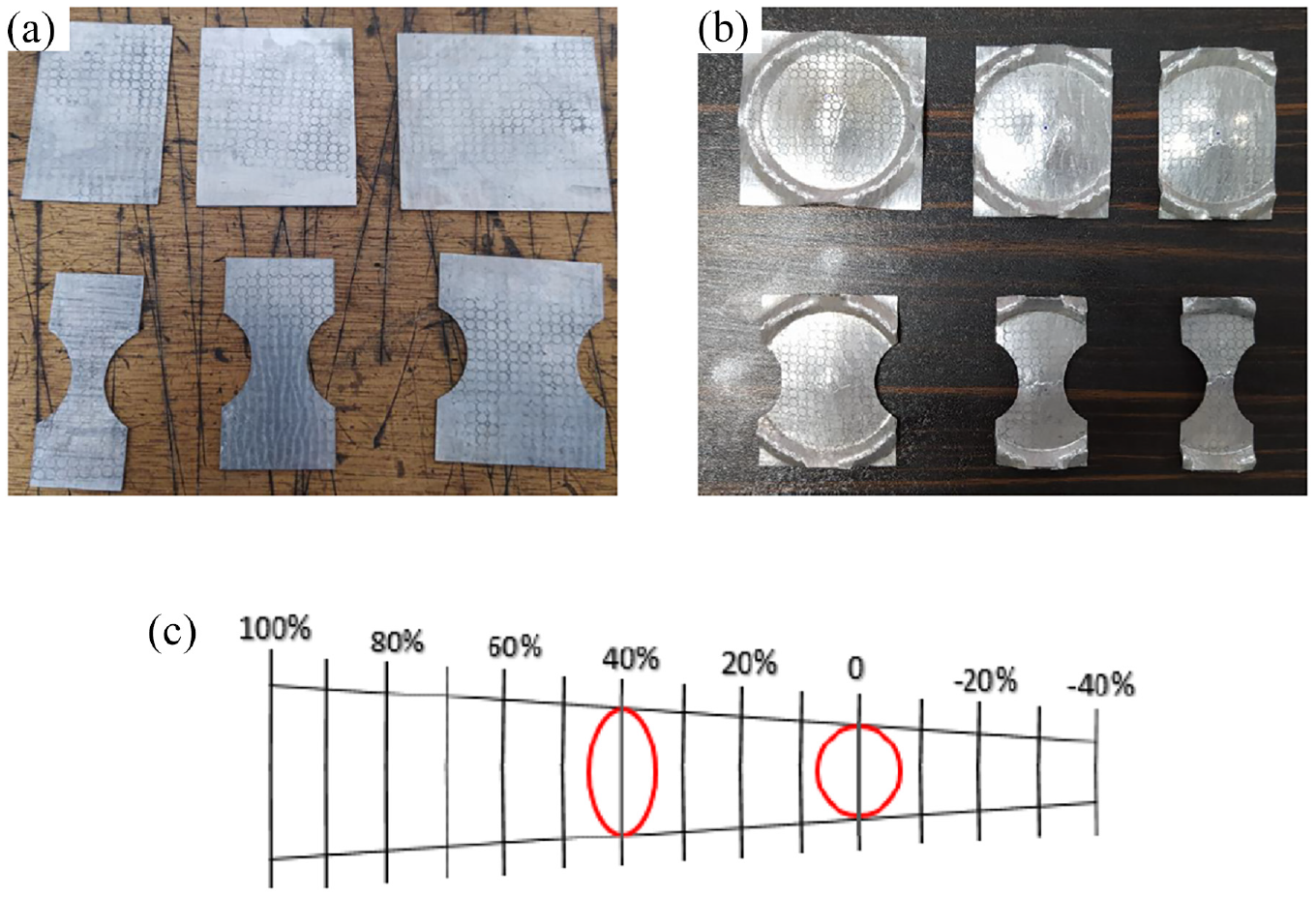
(a) Marked samples, (b) samples after the Nakazima test, and (c) the Mylar ruler.
In the next stage, a SANTAM STM-50 hydraulic press was employed to conduct the Nakazima test. For this purpose, the marked sample was located in the die. Then, the die was fastened tightly by screws, and the whole set was placed under the press machine. Also, the hemispherical punch was installed on the movable jaw of the press machine. Then, the moving jaw drew the sheet until crack formation. A sharp decrease in the load-displacement diagram, monitored by the machine, was considered the stop criterion in the Nakazima test. The deformed samples after the test are depicted in Figure 4(b).
After the Nakazima test, the circular grids, marked on the initial samples previously, deformed to the elliptical grids. By selecting an elliptical grid sufficiently close to the crack region and measuring the small and large diameter of the ellipse for each sample, various points of the forming limit curve (FLC) could be obtained. For this purpose, the large and small diameters of the related elliptical grids were measured by a Mylar ruler, as shown in Figure 4(c). This graded transparent bar was placed on the ellipse, with grade lines parallel to the intended diameter. By moving the ruler on the ellipse, the value of diameter could be found with an accuracy of 0.1 mm. Finally, the major and minor engineering stresses were calculated through equations (1) and (2) 41 :


“d1,”“d2,” and “d0” introduce the ellipse’s large and small diameter and the initial circular grid diameters, respectively. By performing the above calculations for all samples of each cycle, six points were obtained in the diagram, and FLD was drawn up by bypassing a curve from these points. 41
Results and discussion
Microstructure
The microstructure of Al/Ti multilayered composite after altered cycles of ARB is shown in Figure 5. After the first cycle (Figure 5(a)), a well-bonded and non-delaminated composite is achieved. As can be seen, layers are continuous and coherent across the interface. In the subsequent cycles, the Ti layer initiates to neck and fracture in the Al matrix. 24 Contrary to the first cycle, the second cycle illustrates a ruptured Ti layer in the Al matrix (Figure 5(b)). It has been widely reported that through co-deformation of dissimilar metals, necking and fracture occur in the harder layer first. This behavior originates from the different flow properties of the constituent metals.25,27,42
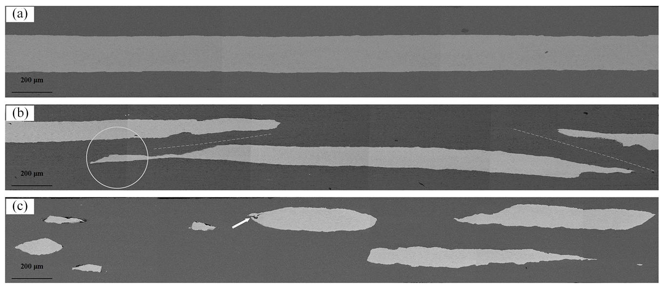
SEM micrographs of the Al/Ti multilayered composite in the (a) first cycle, (b) second cycle, and (c) third cycle.
Additionally, the Ti layer’s discontinuity is also related to the formation of shear bands demonstrated by dashed lines (Figure 5(b)). 28 These shear bands originate from in-plane shear stress at the interface of the adjacent layers. The Al matrix acts as a transfer medium for the load to the Ti layer in the deformation process. 43 When rupturing occurs along with the interface, lenticular fragments of Ti reinforcement form, which is the most prominent feature of the third cycle. 25 One of the fragments is demonstrated by a circle in the middle of the formation (Figure 5(b)). In the third cycle (Figure 5(c)), various sizes of Ti lenticular fragments can be seen. Besides, the white arrow shows a crack on the Ti layer results in a lenticular fragment formation. It should be noted that the crack is nearly parallel to the shear bands described before. Therefore, it may be concluded that the shear bands are the main factor for Ti lenticular fragment formation. The sides’ angles of the Ti fragments may verify this claim.
Figure 6 shows the XRD pattern of Al/Ti composite after three ARB cycles. Only Al and Ti peaks are recognized in the pattern, and no intermetallics are found. 23 Also, the height of the Ti peak is too low in comparison with the Al peak. Compared to X-ray penetration depth, the larger thickness of the surface layer may lead to low detection of the Ti phase. 25
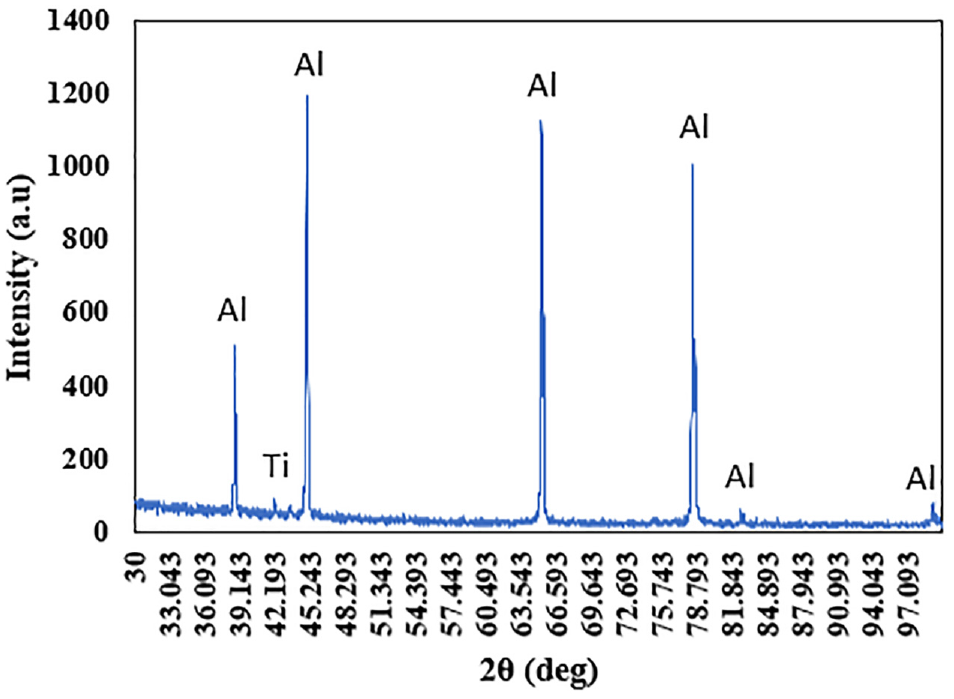
XRD pattern of the Al/Ti multilayered composite after three ARB cycles.
An SEM micrograph and composition profile across the Al/Ti interface is shown in Figure 7 after three ARB cycles. The composition profile indicates the diffusion of the two elements at the interface. 44 As a result of the diffusion, intermixing of the two phases occurs after three ARB cycles. The composition profile reveals a phenomenon recognized as the deformation-induced interdiffusion process. This phenomenon occurs because of the severe plastic deformation imposed through the ARB process. 24 Besides, this composition profile confirms the nonexistence of intermetallic compounds, as stated previously.
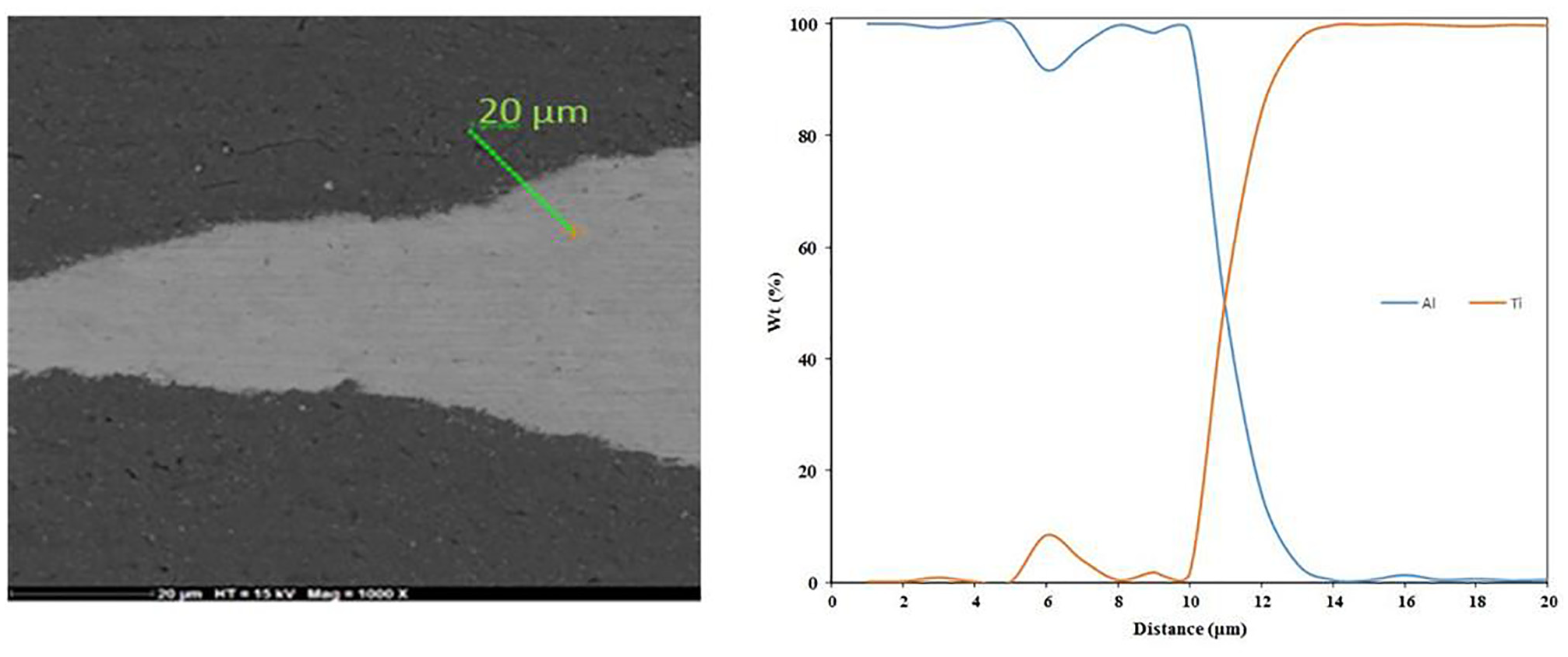
EDX line scan at the interface of Al and Ti layers after three cycles of ARB process.
Mechanical properties
The engineering stress-strain diagrams versus the number of ARB cycles are shown in Figure 8 for both ARBed composites and annealed samples. As ARB proceeds up to the second cycle, the UTS of the composite reaches 176.9 MPa, which is about 98% upper than annealed Al samples. However, in the third cycle, the UTS decreases to 138.25 MPa. In ARBed materials, two primary mechanisms are responsible for strengthening: (1) strain hardening and (2) grain refinement.43,45–47 The first mechanism plays a vital role in the enormous tensile strength increase up to the second cycle. The high level of strengthening originates from the accumulation of dislocations caused by severe plastic strains. 45 A strong proof for this severe plastic strain is the EDX line scan analysis previously shown in Figure 7. Based on this figure, the intermixing of two phases originates from a massive amount of plastic strain. In the third cycle, however, UTS drops to 138.3 MPa. The strength reduction in the third cycle can be explained as follow. As the mixture rule states, the strength of the composite is determined by its constituent phases. In the third cycle, the substantial necking and fraction of the Ti layer, as demonstrated above by Figure 5(c), reduced its impact as a hard layer in overall strength. On the other hand, the role of Al as the soft layer becomes more crucial. However, what should be noticed is that, in the case of this study, rolling mills with an industrial capacity were used, which induced a significant amount of strain on the multilayers composite. This enormous strain increased the temperature of the stack noticeably. Due to the low recrystallization temperature of AA1050, the temperature increase canceled out the work-hardening of previous cycles. Because of that, the Al layer lost its resistance against deformation and resulted in a reduction of strength in the third cycle. 48 On the other hand, the elongation of the composite significantly decreases after the first cycle compared to the annealed sample. As shown in Figure 8, the elongation reaches from 33.7% for annealed Al to 4.22% for one-pass ARBed composite. As illustrated above in Figure 5(b), the formation of shear bands could be strong evidence for this drastic decrease in elongation. By increasing the number of ARB cycles, the microstructural evolution of the composite was recognized by scattering more Ti fragments in the Al matrix. The boundaries of Ti fragments act as a barrier for dislocation movement, causing the localization of strain and a significant reduction in elongation. The formation of shear bands supports this strain localization. Then, elongation reduction is retained with a smooth rate for subsequent cycles and reaches 2.86% after the third cycle. In SPD processes, including ARB, noticeably small grain sizes are achieved because of a high stress level. This well-known phenomenon is known as grain refinement, as stated above. Small grains’ boundaries are barriers to moving dislocations, leading to extreme elongation reduction. 42 The simultaneous increase in UTS and decrease in elongation is a common paradox widely reported by other researchers. 28
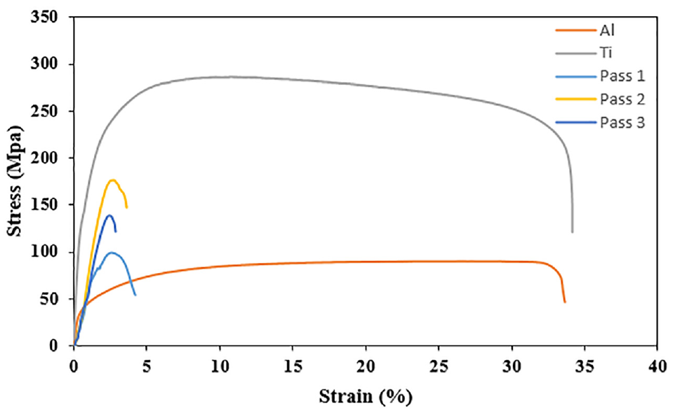
Stress-strain curves of Al/Ti composites for different ARB cycles.
Microhardness variations of the Al and Ti layer are illustrated separately in Figure 9, together with annealed samples. At the first ARB cycle, the microhardness of both phases gets a sharp rise from 25 and 145 to 52.64 and 205.26 VHN, respectively, for Al and Ti layers. 43 The drastic increase in microhardness in the first cycle is mainly due to strain hardening.46,47 It may be concluded that the first ARB cycle is the principal strengthening stage for the Ti and Al layers in the composite because of the rapid increase in the dislocation density. 44 Obviously, microhardness saturates for remained two cycles. As Figure 9 shows clearly, the hardening rate is lower compared to the first cycle. 49 The main reason for increasing microhardness in the second cycle could be grain refinement. 46 Similar to tensile strength but slightly, a drop is seen in microhardness evolution in the third cycle. Due to consistent results between tensile strength and microhardness, the slight decrease in the last cycle could be attributed to neutralization of strain-hardening effect due to temperature increase in the last cycle, as is the case for the tensile strength. Eventually, the microhardness of Al and Ti phases improve by 124% and 47%, respectively, in the whole process of ARB. It is noteworthy to mention that Al and Ti phases have similar trends in microhardness variation. As seen in Figure 9, Ti shows a higher average hardness than Al at different ARB cycles. 28
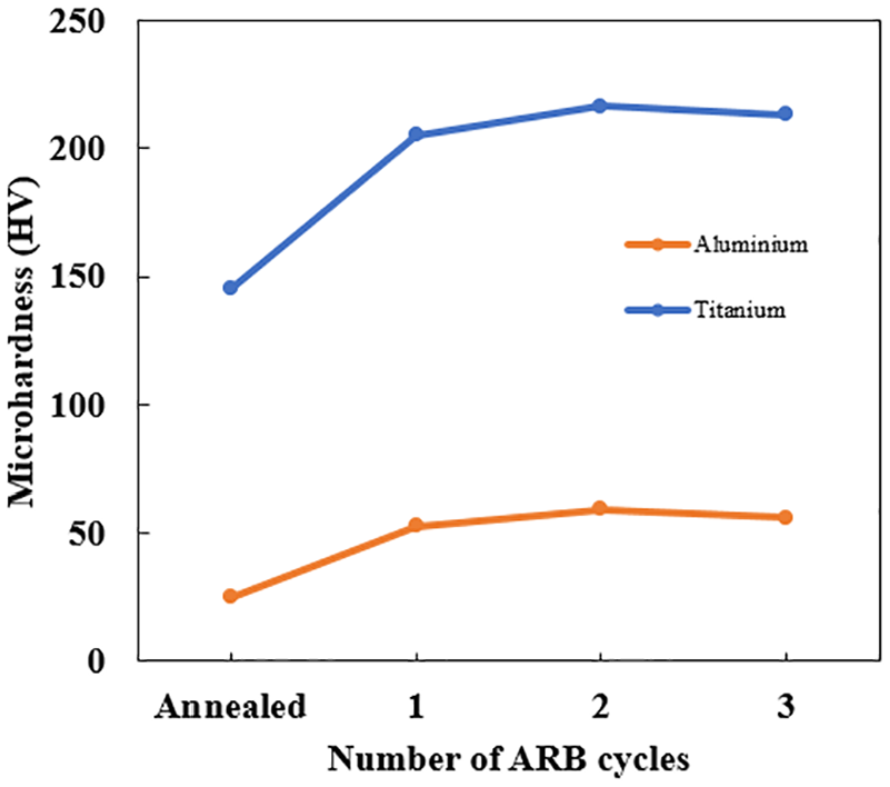
Variations of the microhardness for individual layers with different ARB cycles.
Fractography
The fracture surfaces of the Al/Ti composite after different ARB cycles are shown in Figure 10. The fracture surfaces confirm the excellent bonding of layers by severe plastic strain, as stated previously in Figure 7. As observed from SEM fracture surfaces, no distances exist between layers, and Al and Ti’s layers could be seen clearly and separately for their particular fracture mechanism. For the one pass ARBed composite (Figure 10(a)), a considerable amount of deep dimples is seen in the Al layer, spread all over the interface, which is typical of the ductile fracture. 18 Al with FCC structure has many slip systems, which lead to nucleation of microvoids during the tensile test. In the following, these microvoids coalesce ahead of the main crack, forming mentioned deep dimples.25,50 Unlike Al, the Ti fracture surface consists of smooth surfaces without dimples displaying brittle fracture. 46 For the second cycle (Figure 10(b)), the number of deep dimples decreases drastically in the Al layer. As can be seen, the Al layer is mainly formed by shear regions. Shear bands mentioned in Figure 5(b). produce these shear regions in the Al matrix. Thus, the second cycle shows a gradual transformation of fracture mode in the Al layer, which could be better followed in the next cycle. Although, the Ti layer fracture is still brittle, similar to the previous cycle. After the third cycle (Figure 10(c)), dimples with lower depth and size accompanied by shear zones could be seen in the Al layer due to the strengthening rate of the composite. These shallow dimples, dispersed all over the Al layer fracture surface, change the fracture mechanism of the Al from ductile to shear ductile. However, Ti preserves brittle fracture, as was the case for the first ARB cycle.
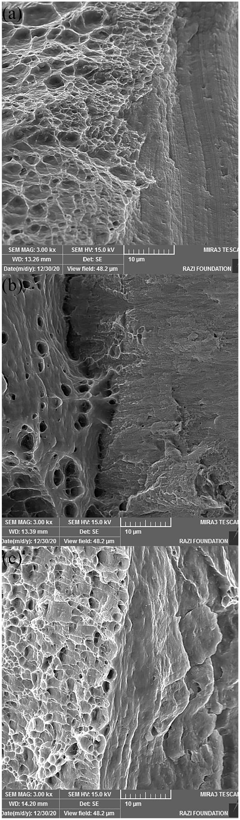
SEM micrographs of fractured surfaces of the Al/Ti multilayered composites in (a) first cycle, (b) second cycle, and (c) third cycle.
Forming limit diagrams
Figure 11 displays the forming limit curves of the annealed Al and ARBed composites at different ARB cycles. As can be seen, the level of forming limit curve, which demonstrates formability, reduces sharply after the first cycle compared to the annealed sample. According to Figure 11, the minimum point of the curve (FLD0) decreases from 22.1%, for annealed Al, to 6.8% after the first cycle. By increasing the number of ARB cycles, the level of FLD decreases slightly, in contrast to the first cycle. In summary, the FLD0 decreases only 1.8% and 1% in the second and third cycle, respectively. It is clear that as ARB cycles proceed, the level of FLD reduces at a significantly lower rate. For comparison, the formability of the composite decreases by 15.3% after the first cycle. However, in the last two cycles, only a 2.8% reduction occurs. The drastic decrease in FLD after the first cycle is chiefly due to strain hardening, which prevents the movement of dislocations. Besides, as a consequence of the considerable plastic strain imposed by the hemispherical punch in the Nakazima test, the layers’ debonding may act as another reason for formability reduction.37,51 It seems that in the last two cycles, an internal factor resists the further reduction of formability. The decrease of grain size by increasing ARB cycles, which is introduced as grain refinement previously, could be the mentioned factor. Furthermore, improved bonding by proceeding ARB passes could act as another reason to stop FLD reduction.37,41 As long as a higher number of ARB passes could be applied on metals, it is not unlikely to improve formability by ARB, as reported by other researchers.37,41,51–53 However, previous works were dedicated to mono-metallic materials, while the present research firstly characterized the formability of a bimetallic multilayer composite. Therefore, further investigations are needed to figure out governing mechanisms on formability.
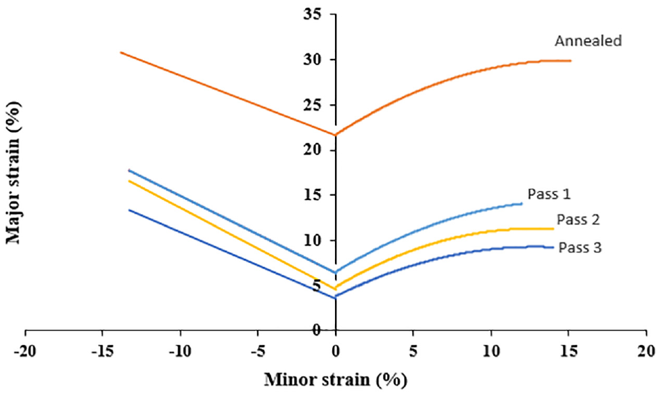
FLDs for annealed Al and Al/Ti multilayered composites after different cycles of ARB cycles.
Conclusions
In the present study, the Al/Ti multilayered composite was fabricated successfully by ARB up to three cycles, and mechanical properties, microstructure, and forming limit diagrams were studied. The following results can be drawn:
The SEM micrographs demonstrated that a continuous three-layered composite with good bonding was obtained after the first cycle. For the second and third cycles, lenticular fragments of Ti were formed by shear bands and homogenously dispersed all over the Al matrix.
XRD pattern showed no intermetallic compounds formed after three cycles, and only peaks of Al and Ti were visible in the pattern. Also, the composition profile obtained by the EDX line scan analysis revealed that a kind of mechanical alloying known as the deformation-induced interdiffusion process occurred at the interface of Al and Ti after three ARB cycles.
The UTS increased continuously to 176.9 MPa up to the second cycle, 98% higher than annealed Al, due to strain hardening. In the third cycle, it dropped to 138.3 MPa due to canceling out of work hardening of Al layer as a result of the temperature increase during rolling and low recrystallization temperature of AA1050. Also, for elongation, it decreased sharply from 33.7%, for annealed Al, to 4.22% after the first cycle. In the last two cycles, the elongation is retained and decreased only by 1.36%.
The microhardness of the Al and Ti layer increased drastically by the first cycle due to strain hardening. For two remained cycles, the microhardness saturated approximately at a fixed value. However, a slight decrease can be seen in the third cycle. Overall, the microhardness of the Al and Ti improved by 124% and 47%, respectively.
The fracture mechanism of the Al layer was changed from ductile to shear ductile after the third pass. This transformation in fracture mode was characterized by the conversion of deep dimples to shallow and bright dimples. However, the Ti fracture was brittle in the entire process.
The FLD of the composite is reduced continuously in the whole process of ARB. For the first cycle, FLD0 decreased from 22.1% to 6.8% because of strain hardening. Moreover, the layers debonding due to significant plastic strain imposed by the hemispherical punch in the Nakazima test could help this extreme reduction. According to grain refinement and improved bonding, the composite tended to stop formability reduction in the final stages of ARB. So, the reduction was only 2.8% for the second and third cycles.
For future works, a comparison can be made between composites produced by ARB and the explosive welding process. Furthermore, FLDs can be obtained for other metallic multilayer composites and be analyzed according to their microstructure.
Footnotes
Declaration of conflicting interests
The author(s) declared no potential conflicts of interest with respect to the research, authorship, and/or publication of this article.
Funding
The author(s) received no financial support for the research, authorship, and/or publication of this article.