
Abstract
Aiming at the problem of acceleration and jerk fluctuation caused by the discontinuity at the corner of the tool path in the continuous short-line machining process, a real-time corner smoothing and interpolation algorithm for realizing the continuous motion of the tool axis jerk is proposed. In the corner smoothing process, the C3 continuity of tool path is realized by constructing a symmetrical PH transition curve satisfying the maximum approximation error constraint between adjacent short lines. In the interpolation process, based on the flexible acceleration and deceleration control method, the feed rate, chord error, acceleration, and jerk constraints are considered. For the smooth C3 continuous path, the acceleration and deceleration profile with jerk-continuous is used for velocity planning and interpolation, and the continuous motion of the tool axis jerk is realized. In this paper, the proposed method is compared and analyzed with the C2 continuous algorithm and the traditional point-to-point interpolation algorithm through simulation and experiment for the same tool path. The results show that the jerk fluctuation of the proposed algorithm is reduced by 60.36% on average compared with the C2 continuous algorithm, and the processing time is reduced by 19.5% compared with the point-to-point interpolation algorithm. It proves that the proposed algorithm can effectively reduce the vibration of the machine tool and improve the processing efficiency.
Keywords
Introduction
When the CNC machine tool is processing complex parts, it will discretize the tool path through the computer-aided manufacturing (CAM) software, generate a continuous short line segment in the form of G01, and send it to the CNC system. 1 In the machining process, because the corner of G01 tool path is only continuous position (C0), and the discontinuity in tangential and normal directions will lead to the fluctuation of acceleration and jerk of each axis of the machine tool, which will cause tool vibration, destroy the surface smoothness of the parts and reduce the machining quality.2–4 In order to improve the machining efficiency and quality of G01 tool path, experts and scholars have carried out in-depth research on corner smoothing and interpolation technology.5–7 That is, the high-order spline curve is used to interpolate the corner to generate a smooth tool path, and then the corresponding acceleration and deceleration(ACC/DEC) control method is selected for velocity planning and interpolation, which provides interpolation instructions for the position controller of the CNC system to achieve smooth and continuous feed motion.
In terms of corner smoothing, the commonly used spline curves are NURBS curves,8,9 B-spline,10–12 and Bezier curves.13–15 However, since there is no definite analytical relationship between the arc length of the above spline curve and the parameters, the arc length in the corner smoothing algorithm must be estimated by the iterative numerical algorithm.16–18 The higher the arc length accuracy is required, the larger the calculation amount is, and the longer the operation time of the computer is, which is not suitable for real-time application. The Pythagorean-Hodograph (PH) curve 19 provides the analytic relationship between the arc length and the curve parameters. The arc length calculation is small and the operation time is short, so it has attracted extensive attention in the study of real-time corner smoothing. Jahanpour 20 proposed a high-speed contour processing algorithm based on C 2 continuous quintic PH curve. Shi et al.21,22 proposed a corner smoothing algorithm based on quintic PH curve, and realized the smooth transition of machine tool motion combined with dynamic forward speed planning algorithm. Farouki 23 proposed a seven-degree PH curve corner smoothing algorithm based on G 2 continuity. At present, most corner smoothing algorithms based on PH curve are limited to the second-order continuity of G 2 and C 2 . Although the calculation efficiency is improved to a certain extent, the C 2 continuous path after smoothing can only ensure continuous motion of tool axis acceleration. Compared with the continuous trajectory of C 3 , the continuous trajectory of C 2 has large fluctuation in the jerk during the operation of the machine tool. 24 The discontinuity and high fluctuation of the jerk curve will lead to the unstable motion of the machine tool and affect the machining quality. Therefore, the construction of C 3 continuous PH curve is of great significance for realizing real-time corner smoothing and tool axis jerk-continuous motion.
But smooth trajectory does not mean smooth movement. 25 In order to ensure the continuity of tool axis movement in the machining process, in terms of ACC/DEC control,26–28 appropriate ACC/DEC profile should be selected to match the smooth tool path. The continuous tool path of C 2 can realize the continuous motion of tool axis acceleration by using the ACC/DEC profile with acceleration continuous for velocity planning and interpolation. Good jerk characteristic is an essential condition to ensure the processing quality. 29 The ACC/DEC profile with jerk-continuous must be used for velocity planning and interpolation of C 3 continuous tool path in order to reduce the tool vibration, improve the machining quality, and realize the continuous movement of tool axis.
To sum up, in order to simultaneously realize the real-time performance of corner smoothing and interpolation algorithm and the continuous movement of tool axis jerk, a real-time corner smoothing and interpolation algorithm based on C 3 continuous PH curve is proposed in this paper. The algorithm is realized by inserting the designed symmetrical PH curve between the linear tool paths. Considering the maximum approximation error and linear segment length constraints, the position of control points is calculated to realize the C 3 continuity of PH curve and linear segment connection point. Based on the flexible ACC/DEC control, the velocity planning and interpolation of the smooth tool path are carried out by using the jerk-continuous ACC/DEC profile to realize the continuous motion of the tool axis jerk.
In this article, a real-time corner smoothing and interpolation method to realize the continuous movement of tool axis jerk is proposed. The rest of this paper is organized as follows: A real-time corner smoothing algorithm based on C 3 continuous PH curve is proposed in Section 2. Based on the ACC/DEC profile with jerk-continuous, a real-time interpolation algorithm is proposed in Section 3. The effectiveness and superiority of the algorithm are verified by simulation and experiment in Section 4. The analysis is summarized in Section 5.
Real-time corner smoothing algorithm
PH curve
Let
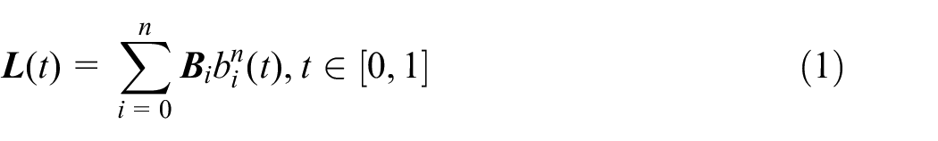
Where
When
The polynomial
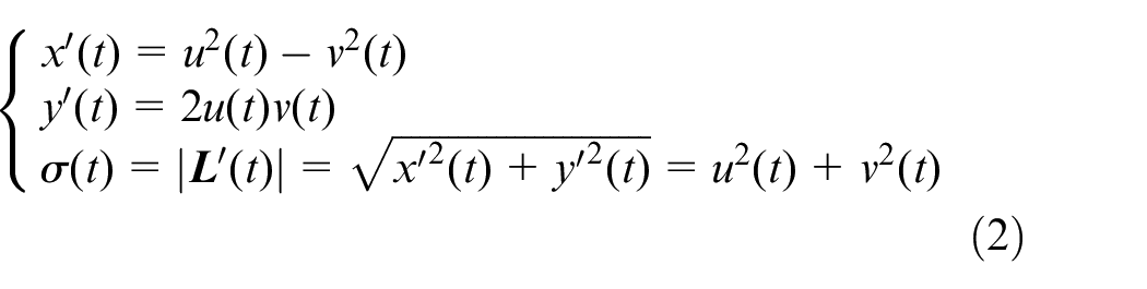
The parameter velocity
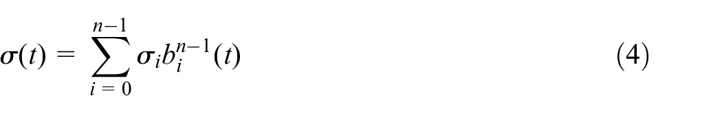
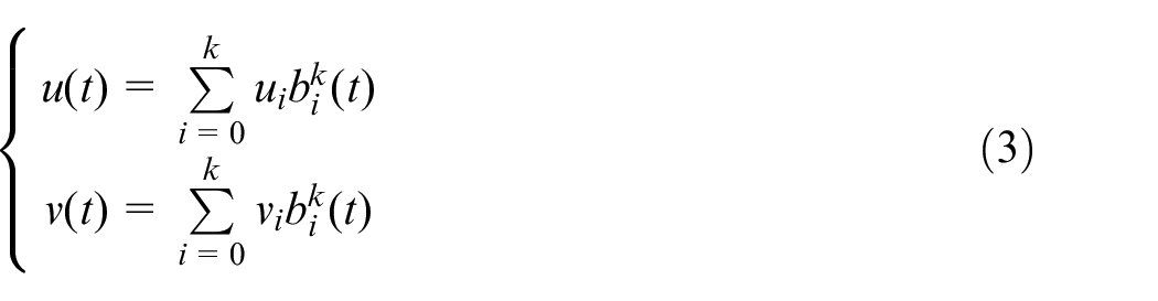
According to the coefficients of
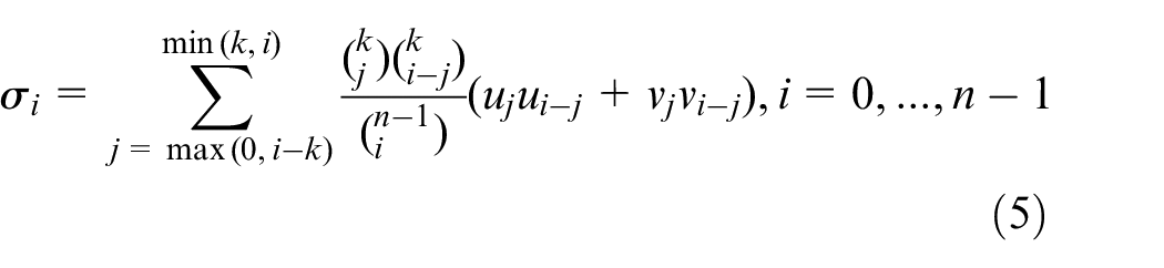
The parameter velocity
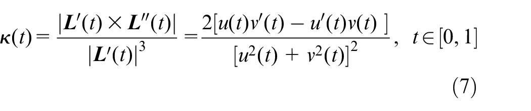
In addition, the curvature corresponding to the PH curve is:
C 3 continuous PH curves
In order to ensure the continuous movement of the tool axis jerk in the machining process, the C 3 continuity of the trajectory with respect to arc length should be ensured first, that is, the C 3 continuity of the tool path should be realized. 25 Therefore, a C 3 continuous real-time corner smoothing algorithm is proposed in this section by inserting a symmetric PH curve between two continuous short lines for corner transition. The designed symmetrical PH curve is expressed as:
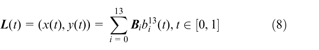
In order to construct the C 3 continuous PH curve, the sixth degree Bernstein polynomial is introduced as:
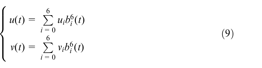
As shown in Figure 1,
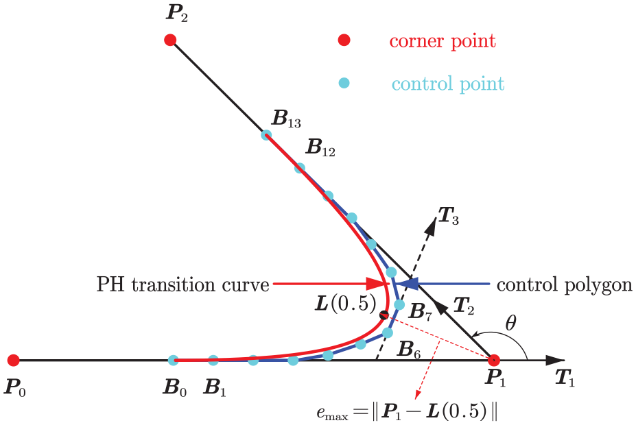
C 3 continuous PH transition curve.
In order to achieve the continuity of acceleration and jerk at the junction points
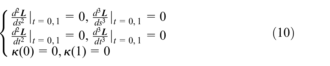
As shown in Figure 1, because the designed spline curve is symmetrical, the control polygon composed of control points is also symmetrical, and the following equation can be obtained:
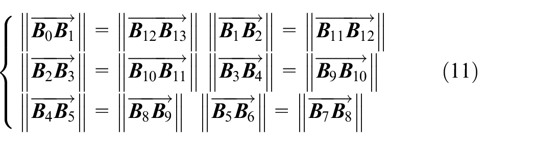
According to equations (2), (9), (10), (11), the control points in equation (8) have the following relationship:
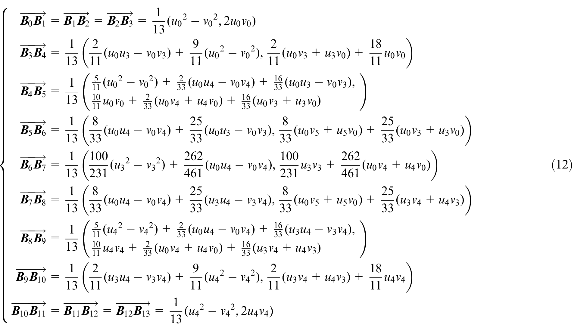
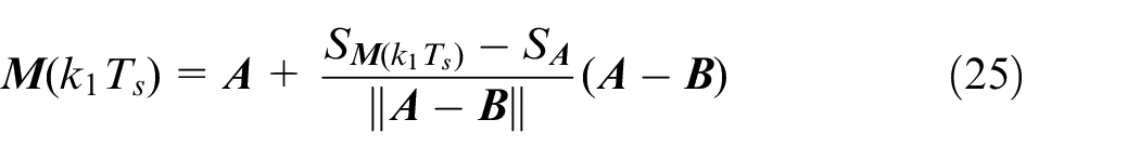
According to equation (12), the relative position between control points is determined. Considering the symmetry of PH curve, the exact position of control points is expressed as follows:
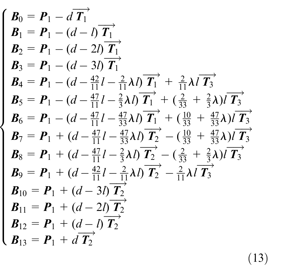
The detailed derivation process of equation (13) is shown in Appendix 1.
As shown in Figure 25,
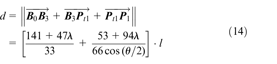
The detailed derivation process of equation (14) is shown in Appendix 2.
Maximum approximation error constraint
Since the constructed PH curve is symmetric, the maximum approximation error
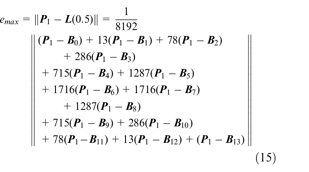
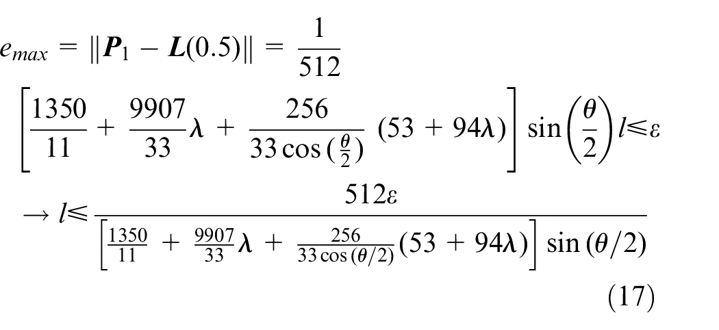
Substituting equations (13) and (14) into equation (15), the maximum approximation error
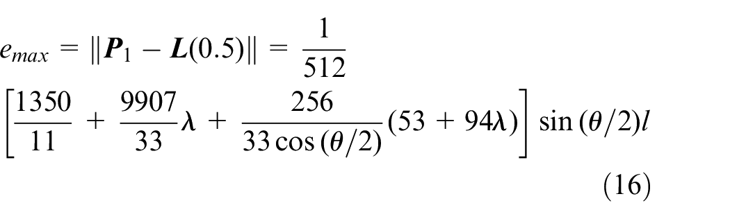
The expression of the maximum approximation error
Linear segment length constraint
In the process of constructing the PH transition curve, in order to avoid spline overlap as shown in Figure 2, this paper uses the midpoint constraint method
31
to limit the maximum allowable length of
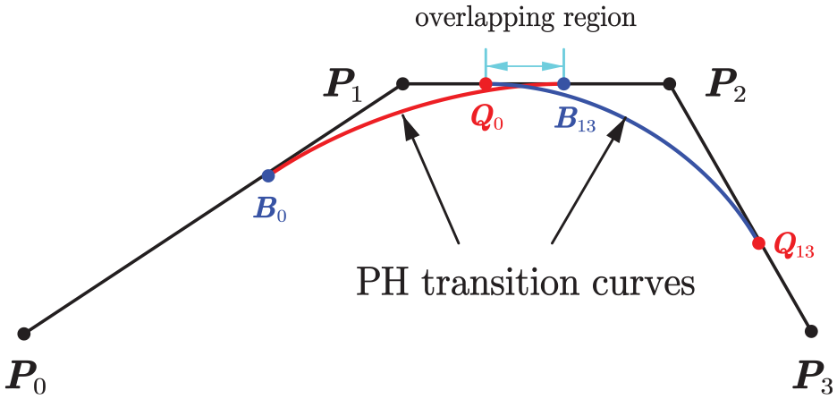
Corner overlapping contour.
Therefore, the length l of the control polygon is constrained to:
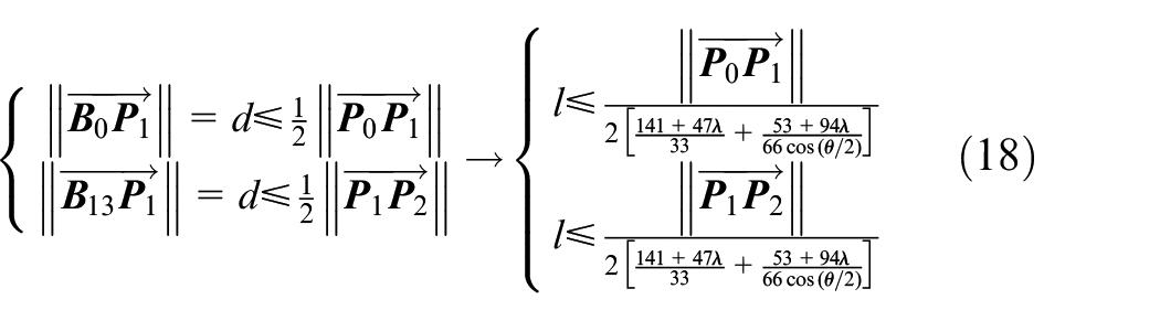
Combining equations (17) and (18), the control polygon length l of the constructed PH transition curve is constrained as:
It can be seen from equation (19) that shortening the length l of the control polygon will lead to the decrease of the maximum approximation error, so under the constraint conditions of equation (19), the maximum approximation error is always within the error limit defined by the user.
Calculation of arc length of PH curve
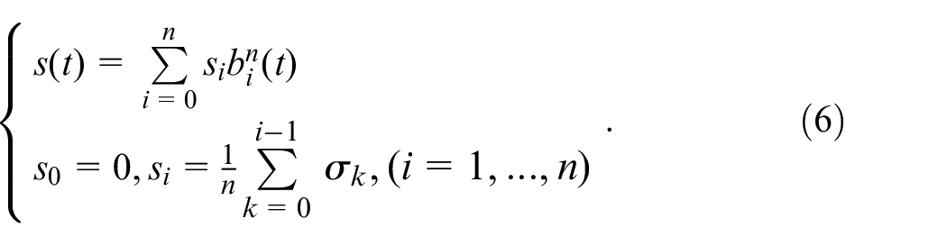
The coefficient of arc length function
Combined with the relationship between
By substituting the parameter velocity coefficient
Summary of real-time corner smoothing algorithm
The flowchart of real-time corner smoothing algorithm is shown in Figure 3. First, read the corner data point information (three consecutive position points
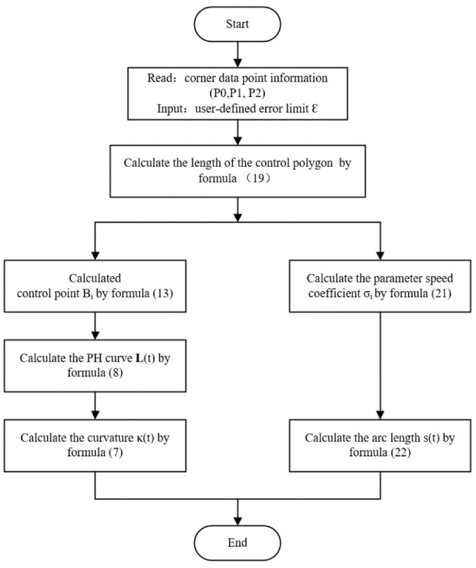
Flowchart of corner smoothing algorithm.
The above-mentioned entire corner smoothing process based on C 3 continuous PH curve does not require any iterative calculation, and the geometric information such as arc length and curvature of any point on the PH curve can be analytically obtained, which provides convenience for the interpolation process. This is very beneficial to the realization of real-time corner smoothing and interpolation.
Real-time interpolation algorithm
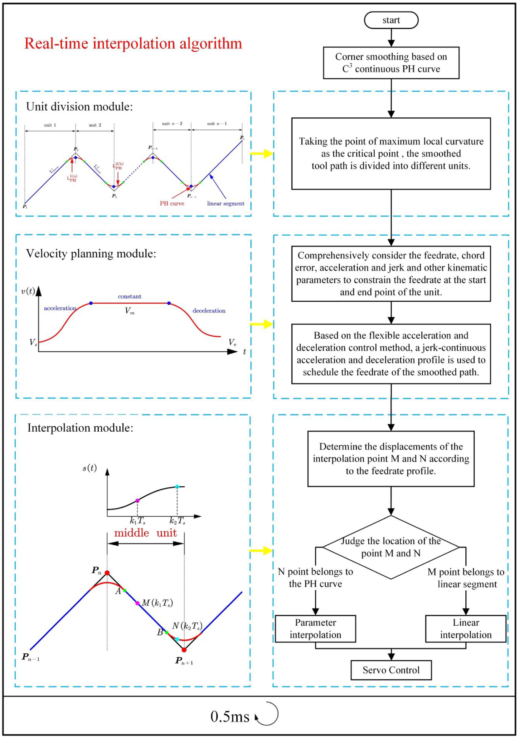
The real-time corner smoothing algorithm proposed in Section 2, the C 3 continuity of the tool path is realized by inserting the PH transition curve at the corner of the continuous short line segment, but the smoothing trajectory does not mean smooth and continuous motion. In order to realize the continuous movement of tool axis jerk, a real-time interpolation algorithm based on the flexible ACC/DEC control method is proposed in this section. The real-time interpolation process is shown in Figure 4, which mainly includes three modules, namely, unit division module, velocity planning module, and interpolation module.
Real-time interpolation flowchart.
Unit division module
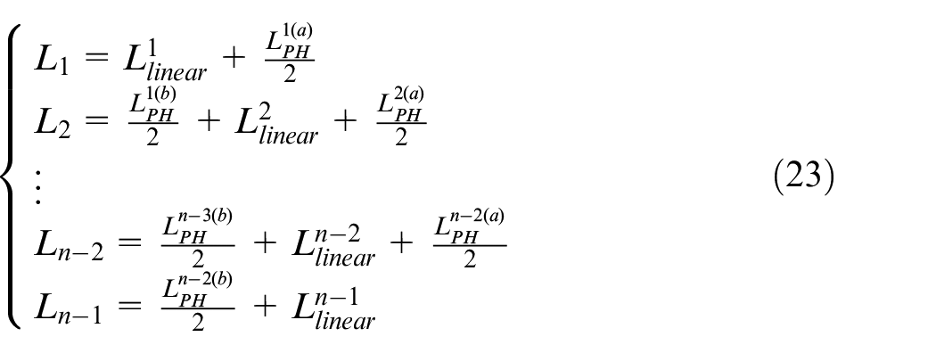
Function of unit division module: the tool path after C 3 continuous corner smoothing algorithm is divided into different planning units composed of linear segments and PH curves.
The smooth tool path consists of a red C
3
continuous PH curve and the remaining blue linear segments in the original linear path. The whole path contains
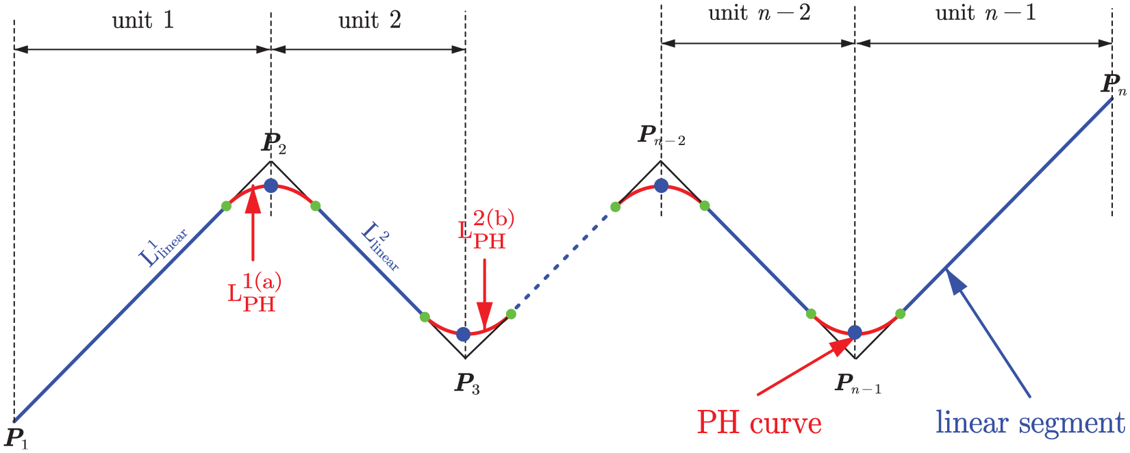
Diagram of unit division.
Real-time corner smoothing algorithm is sufficient to complete a corner smoothing in a sampling period. At the same time, based on the analytic calculation of arc length and curvature of PH curve, the geometric information of curvature and arc length of any point on PH curve can be obtained in real time, which provides a basis for the identification of critical points.
It can be seen from Figure 5 that the local maximum curvature point appears at the midpoint of the PH curve
Velocity planning module
The function of the velocity planning module: Based on the flexible ACC/DEC control method, the velocity planning of the smooth tool path is carried out by using the jerk-continuous ACC/DEC profile.
As shown in Figure 5, the starting point and end point of each unit are the local maximum curvature points of the PH curve. If the feed rate at this point is not constrained, acceleration and jerk may exceed the limit set by the machine tool. Therefore, in order to avoid the fluctuation of acceleration and jerk when the tool moves to the maximum curvature point, the kinematic parameters such as feed rate, chord error, acceleration, and jerk are comprehensively considered in this section to constrain the starting velocity Vs and final velocity Ve of the unit. 26
The feed rate of the unit starting point and end point is calculated as:
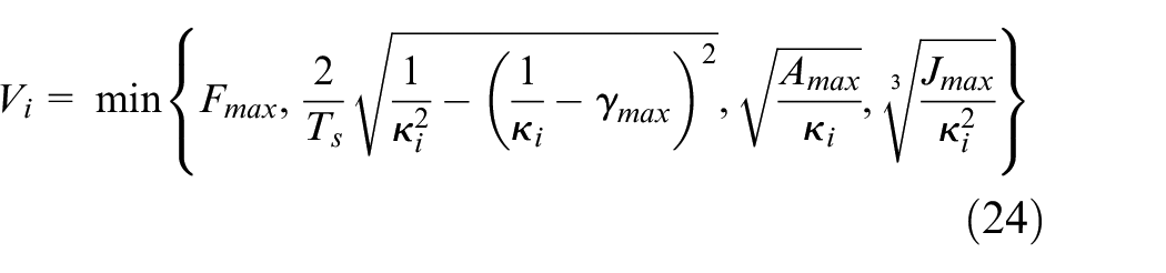
Where;
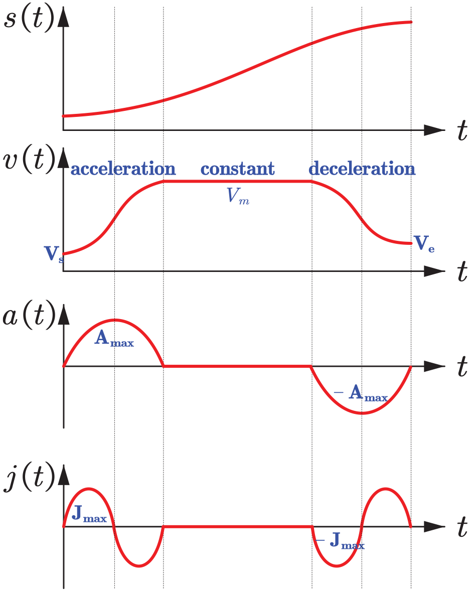
Jerk-continuous ACC/DEC profile.
Real-time interpolation module
The function of the real-time interpolation module: the displacement of each sampling period is calculated according to the velocity curve in the velocity planning module, and the appropriate interpolation method is selected to calculate the corresponding interpolation point coordinates, which provides real-time interpolation instructions for the position controller of the CNC system.
According to the velocity curve in the velocity planning, the displacement of each interpolation period can be obtained as s(t), where t = kTs (k = 0,1,…), and Ts is a constant sampling period. In real-time interpolation, only after the current unit completes the interpolation, the next unit starts the corner smoothing and interpolation. Since the tool path after corner smoothing is a mixed path composed of linear segment and PH curve, it is necessary to determine whether the current displacement is located on the linear segment or on the PH curve, so as to select the linear interpolation or parameter interpolation to calculate the interpolation point coordinates. The interpolation process is shown in Figure 7.
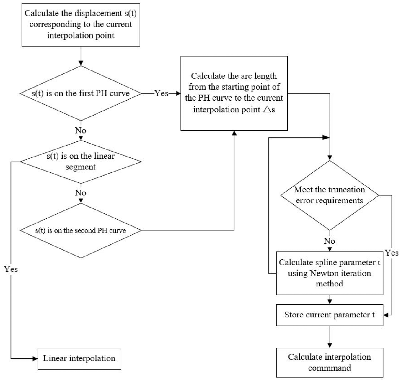
Interpolation flowchart.
As shown in Figure 8, taking the intermediate unit as an example, the real-time interpolation process is illustrated by using two interpolation points
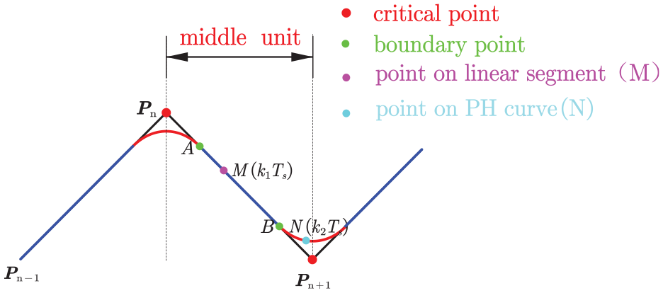
Illustration of the interpolation process.
Point
In addition, the point

The arc length function
Newton iteration process is as follows:
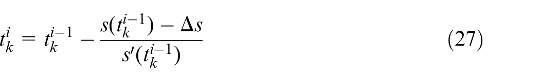
In equation (27),
It should be pointed out that the corner smoothing and interpolation algorithm in this paper is introduced by taking the planar (2D) tool path as an example, but the algorithm can be extended to the spatially distributed (3D) tool path. Because every two adjacent short segments in the spatially distributed tool path are on a 2D plane, the corner smoothing and interpolation process is actually still carried out on a 2D plane.
Simulation and experimental results
The effectiveness of the proposed real-time corner smoothing and interpolation method based on C 3 continuous PH curve is verified by simulation and experiment. Firstly, the linear three-dimensional closed trajectory is used for simulation analysis, which verifies that the algorithm in this paper can realize the continuous movement of tool axis jerk. Then the planar dolphin-shaped trajectory is used to verify the superiority of the algorithm from the maximum approximation error, real-time performance, jerk fluctuation, and processing efficiency. Finally, the effectiveness of the algorithm is verified by milling experiments.
Simulation results
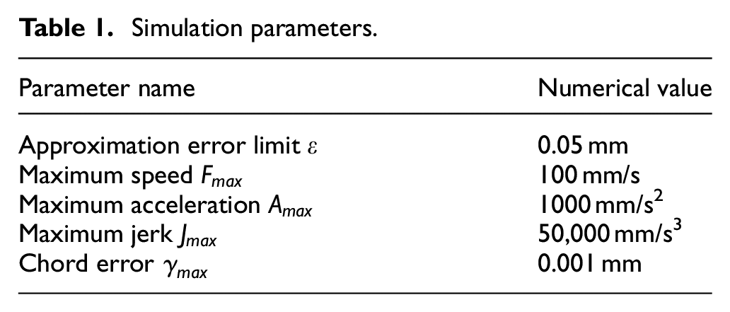
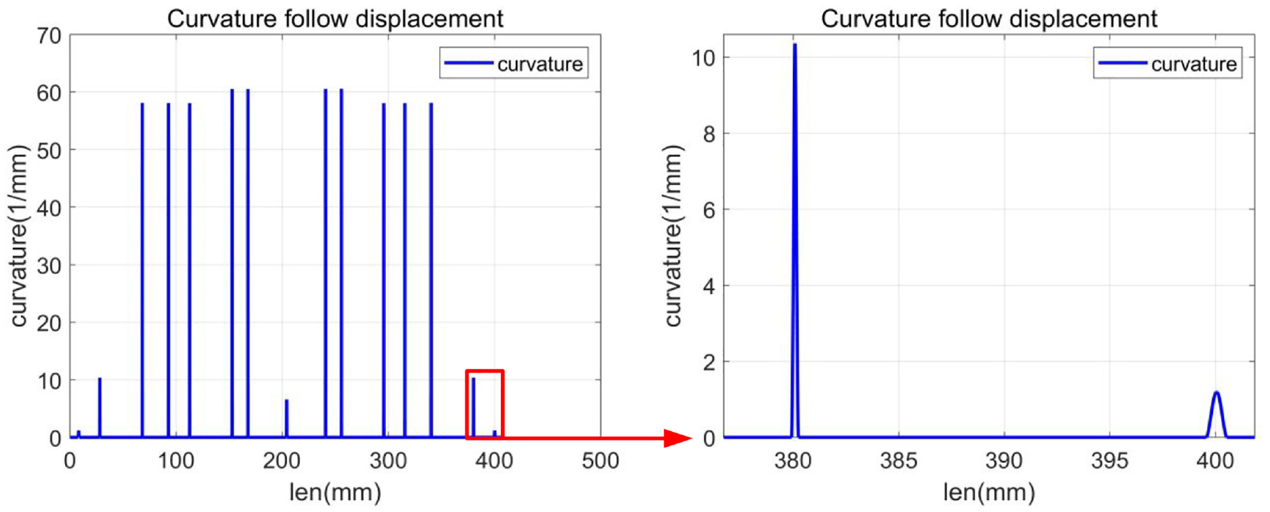
In order to verify that the proposed real-time corner smoothing and interpolation algorithm can realize the continuous movement of tool axis jerk, the simulation analysis is carried out on the MATLAB R2018a platform. In the actual machining process, the tool path is not necessarily on the plane, which is usually composed of short lines connected sequentially in space. Therefore, this paper uses a linear spatial closed trajectory to illustrate the algorithm effect. Considering the performance of CNC system, interpolation period and computer operation efficiency, the sampling period is set to 0.0005 s, and the settings of other simulation parameters are shown in Table 1. The effect of corner smoothing is shown in Figure 9. The variation of the curvature of the interpolation point with the arc length is shown in Figure 10. It can be seen from the figure that the maximum point of local curvature appears at the midpoint of the spline curve, reflecting the symmetrical distribution of the PH curve.
Simulation parameters.
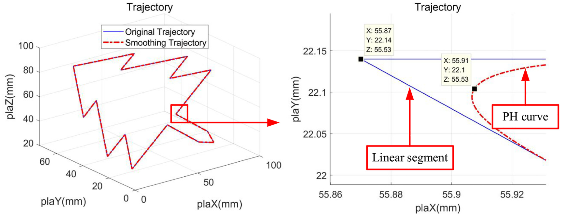
3D trajectory smoothing effect.
Variation of curvature with arc length.
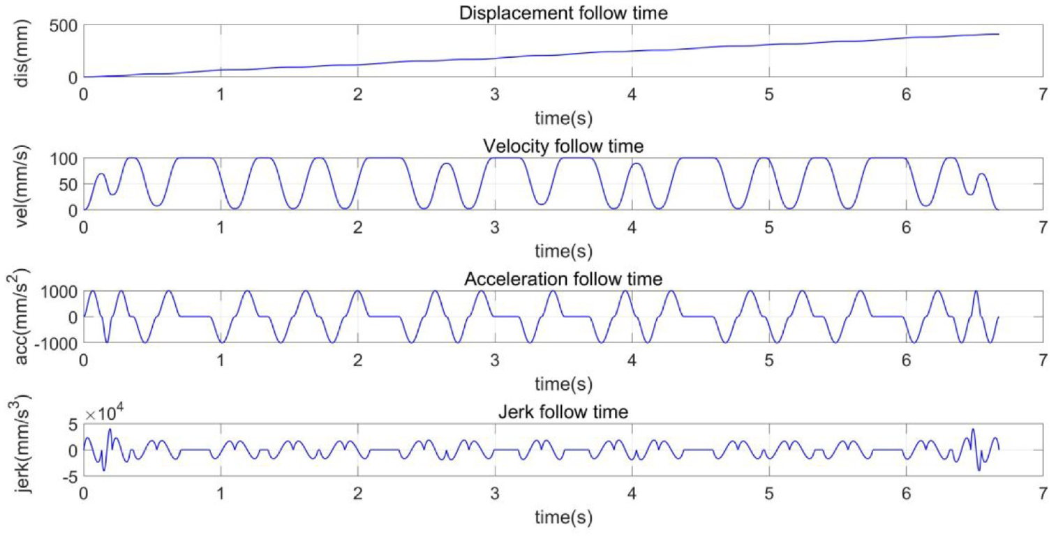
The kinematics curve of each unit is shown in Figure 11 after the velocity planning and interpolation of the smooth tool path are carried out by using the jerk-continuous ACC/DEC profile. Interpolation curve of each axis, velocity curve, acceleration curve, jerk curve, as shown in Figure 12. The blue solid line represents X axis, the green dotted line represents Y axis, and the red dashed line represents Z axis. It can be seen from Figure 12 that within the limit range of the set kinematic parameters, the velocity, acceleration and jerk of the tool axis are continuous. It is effectively verified that this algorithm can realize the continuous movement of tool axis jerk.
Kinematic curve of tool axis.
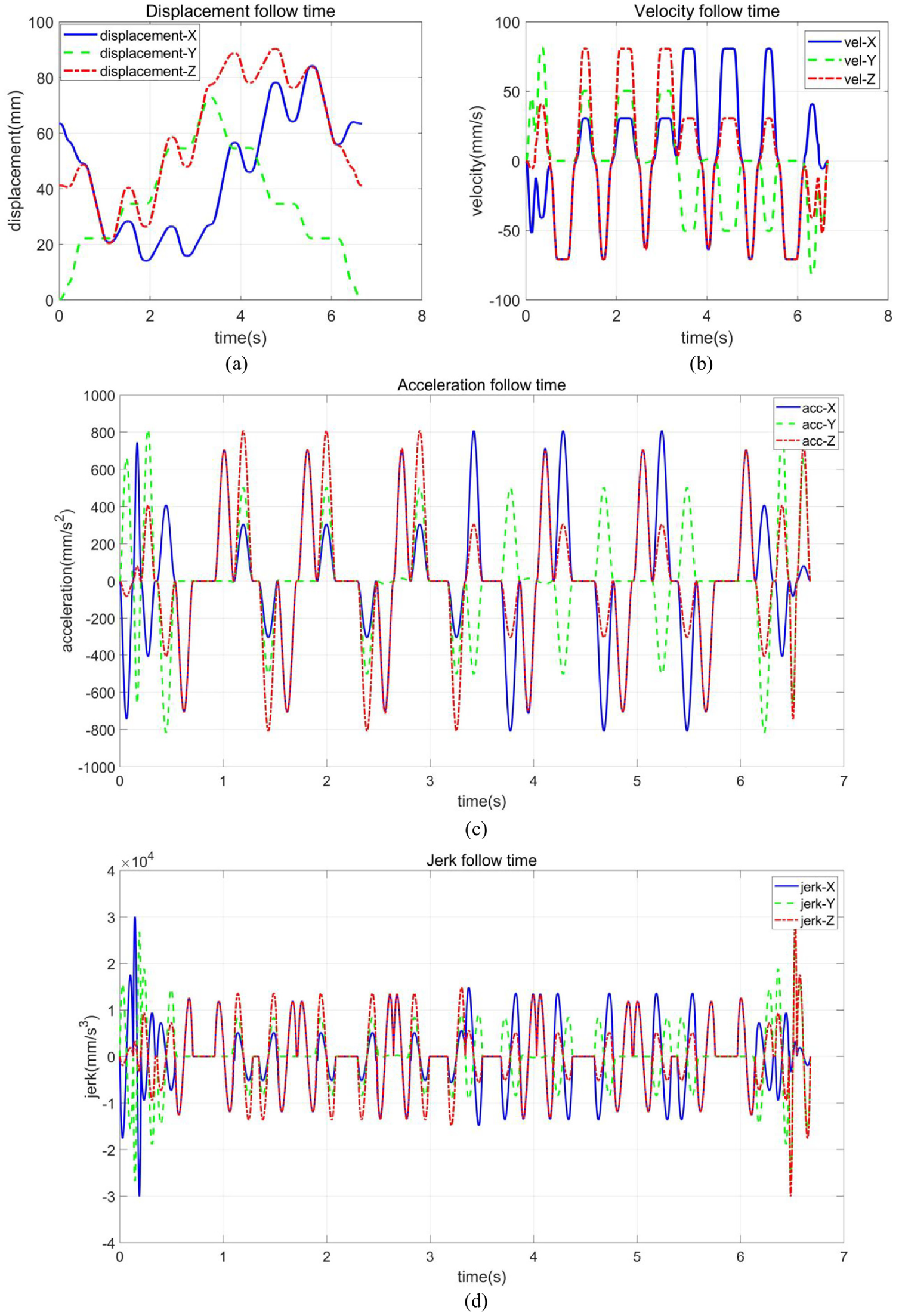
(a) Interpolation curve, (b) velocity curve, (c) acceleration curve, and (d) jerk curve.
In order to better verify the universality and superiority of the algorithm, the planar dolphin-shaped trajectory containing acute angle, right angle and blunt angle is further used for simulation. The superiority of the algorithm is verified by simulation analysis from four aspects: maximum approximation error, real-time performance, jerk fluctuation, and processing efficiency.
The total length of the dolphin-shaped trajectory is 578.12 mm, the longest line length is 35.52 mm, and the shortest line length is 4.89 mm, with 43 corners. Setting the error limit to 10 μm, the effect of corner smoothing is shown in Figure 13. It can be seen from the local amplification diagram of the corner that the maximum approximation error appears at the midpoint of the PH curve. It can be seen from the data point coordinates of the Y axis that the maximum approximation error between the smooth path and the original linear path is constrained to the error limit of 0.01 mm defined by the user.
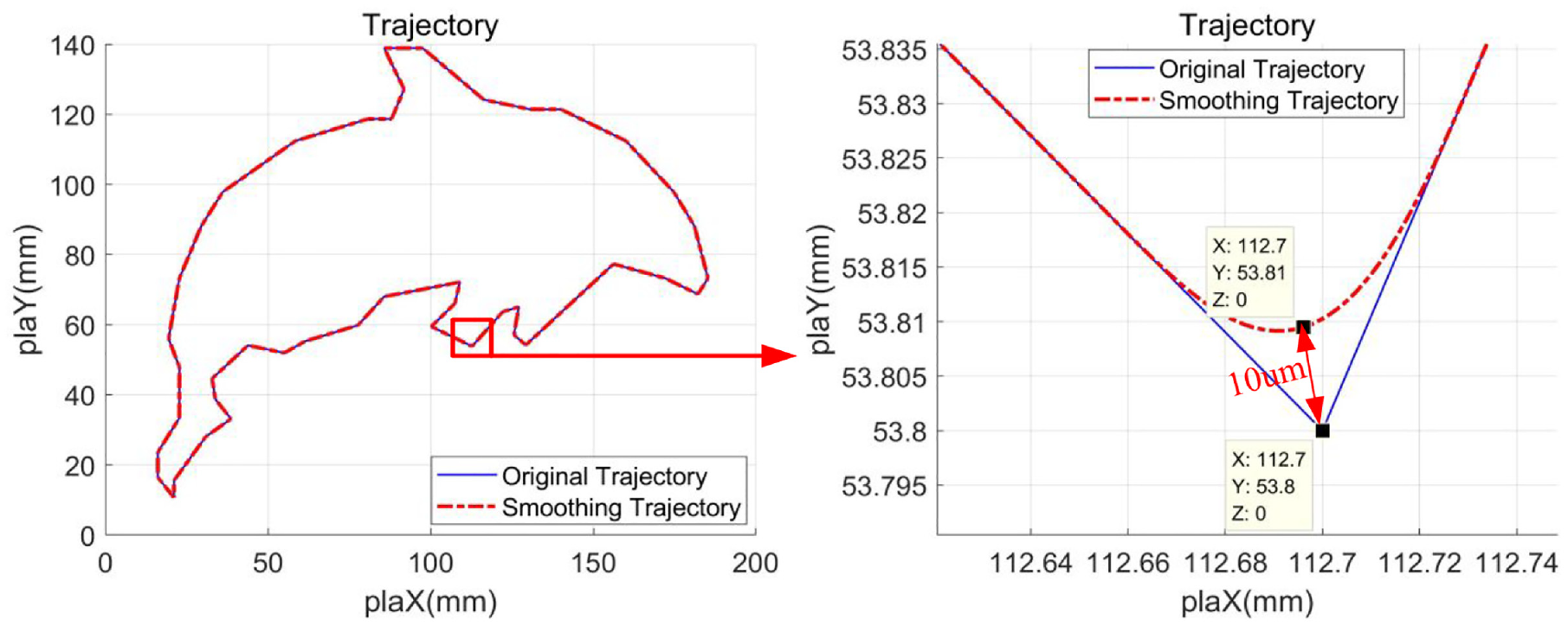
Smoothing effect of dolphin-shaped trajectory.
NURBS curve and B-spline are often used for corner smoothing in trajectory smoothing technology, but there is no definite analytical relationship between the arc length of the above curve and the spline parameters. To obtain sufficient and accurate arc length, it is necessary to set smaller estimation error, which greatly increases the calculation amount of arc length and is not suitable for real-time application.
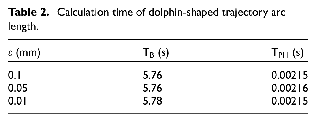
The PH curve used in this paper, the arc length can be calculated analytically, which reduces the amount of calculation and improves the calculation efficiency. In order to verify the real-time performance of the algorithm in this paper, C
3
continuous B-spline
12
and C
3
continuous PH curve are used to smooth the dolphin-shaped trajectory respectively. The calculation time of arc length is shown in Table 2, where TB and TPH represent the average time (10 times of calculation) required to calculate the arc length of the whole tool path by using the corresponding corner smoothing method, and
Calculation time of dolphin-shaped trajectory arc length.
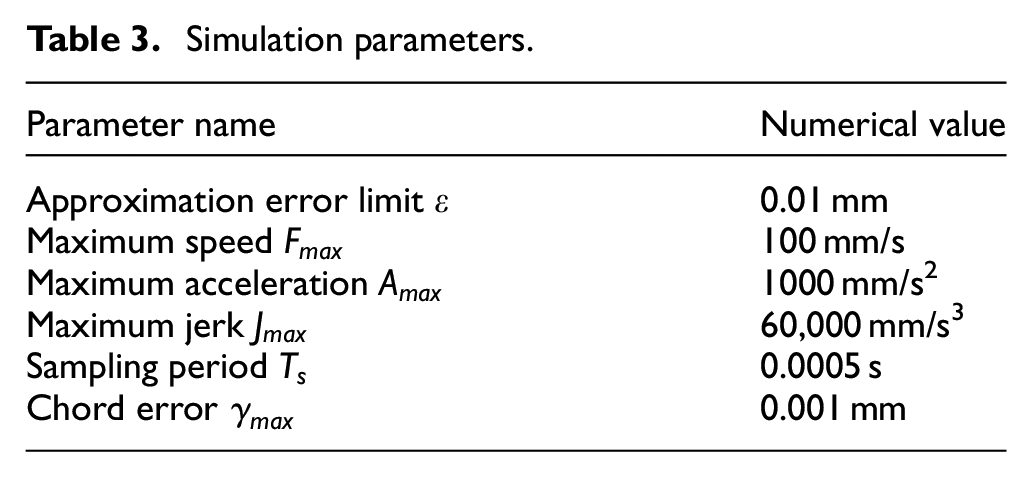
The C 2 continuous smoothing algorithm based on PH curve 21 can only realize the continuity of tool axis acceleration. Compared with the C 2 continuous algorithm, the C 3 continuous algorithm proposed in this paper can realize the continuous movement of tool axis jerk. To illustrate this point, the above-mentioned dolphin-shaped trajectory is used as the original linear path for simulation verification. The C 2 continuous path and the C 3 continuous path after the two corner smoothing algorithms are respectively interpolated in real time. The simulation setting parameters are shown in Table 3.
Simulation parameters.
Since the dolphin-shaped trajectory is a flat profile, only the jerk curves of the X and Y axis are compared and analyzed here. As shown in Figure 14, the jerk curve interpolated by the C 2 continuous smoothing algorithm has abrupt changes at the corners and large jerk fluctuations, even exceeding the maximum jerk limit at some corners. The jerk curve of the algorithm in this paper is smoother than that of the C 2 algorithm.
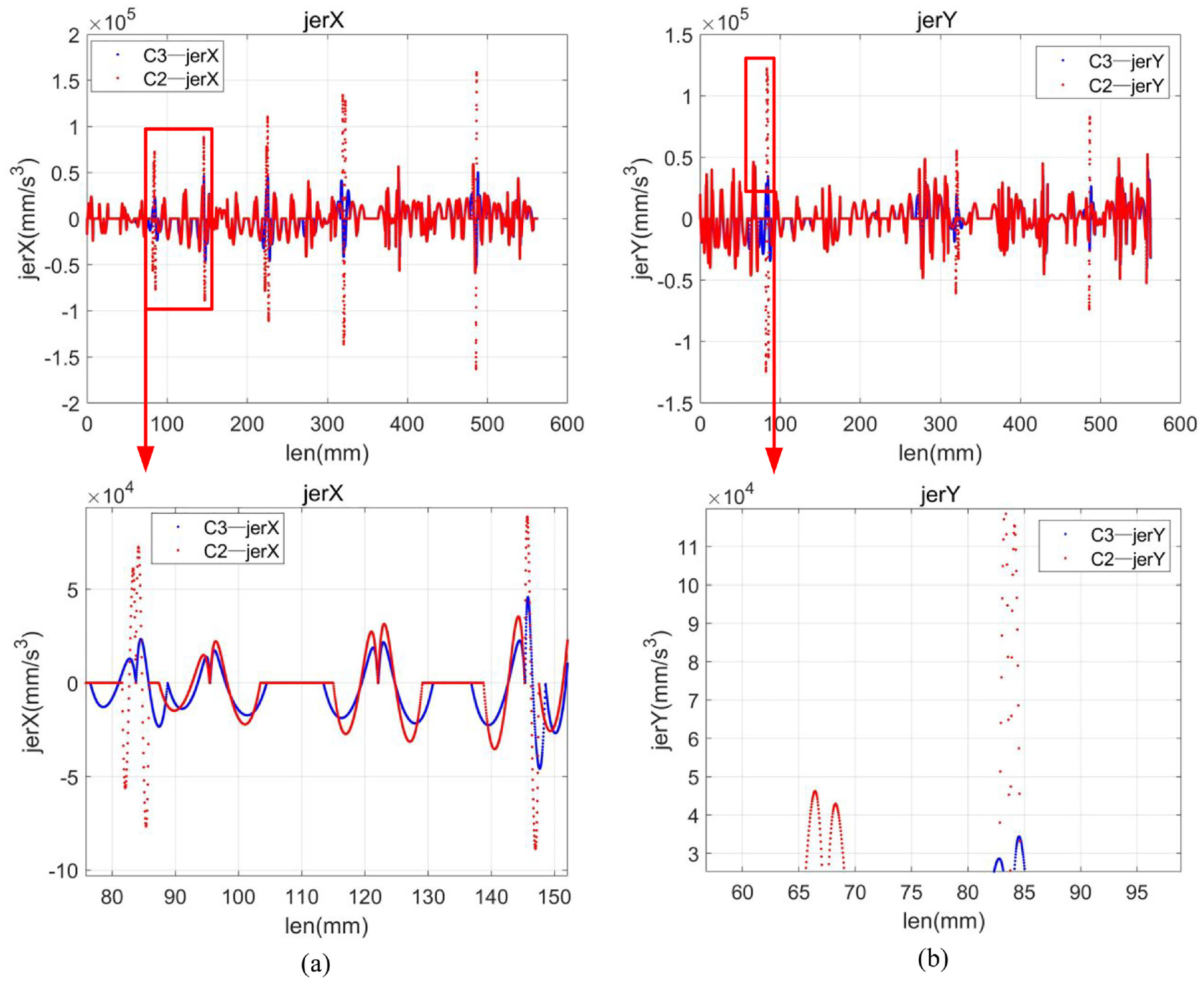
(a) X axis jerk comparison and (b) Y axis jerk comparison.
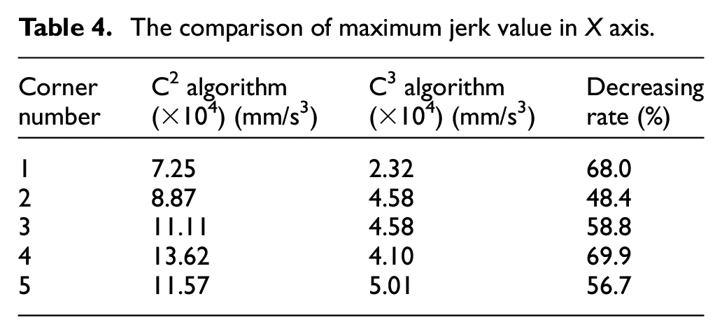
The maximum X axis jerk of the two algorithms at five typical corners are compared, as shown in Table 4. Compared with C 2 algorithm, the algorithm in this paper reduces the jerk fluctuation by 60.36% on average, and the jerk curve is smoother, which reduces the machine vibration and improves the machining quality. It is verified that the algorithm can realize the effectiveness of the continuous movement of the tool axis jerk.
The comparison of maximum jerk value in X axis.
In the actual processing, the real-time corner smoothing and interpolation method proposed in this paper can realize uninterrupted feed motion, while the feed rate of the traditional point-to-point interpolation algorithm at the corner of the path must be reduced to 0, which reduces the processing efficiency.
The velocity curves of the two algorithms for processing the same dolphin-shaped trajectory are compared. As shown in Figure 15, the total processing time of the point-to-point interpolation method is 13.11 s, while that of the proposed algorithm is 10.97 s, which is 19.5% less than that of the point-to-point interpolation algorithm. It effectively shows that the algorithm in this paper improves the machining efficiency on the basis of ensuring the continuous movement of the tool axis.
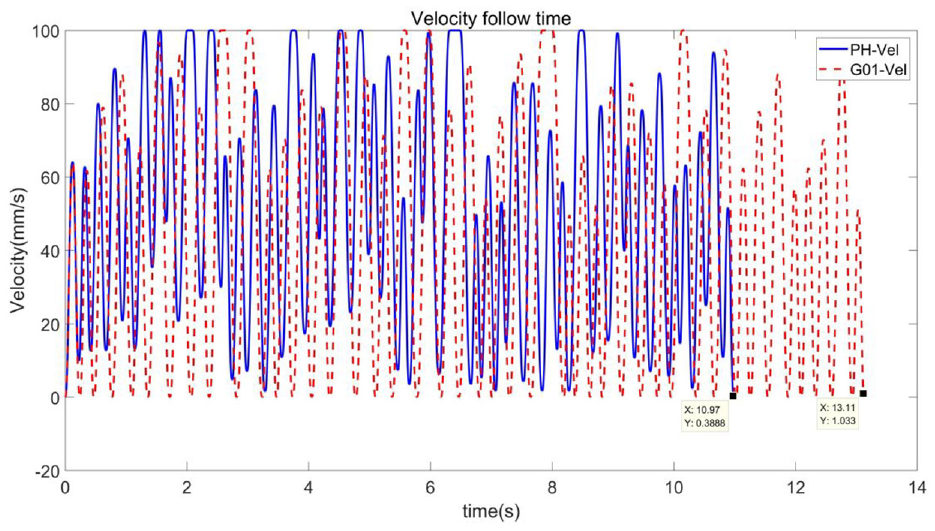
Processing time comparison.
Experimental results
In order to verify that the proposed algorithm can realize the continuous motion of the tool axis acceleration and jerk, the above corner smoothing and interpolation algorithm are integrated into the open CNC system developed by our research group. The CNC system consists of upper machine and lower machine. The upper machine is developed on PC based on Windows XP + RTX 8.1 real-time control software, which can provide real-time calculation and multi-threaded calculation. The lower machine is a motion control card (Gu Gao GTS-800-PG).
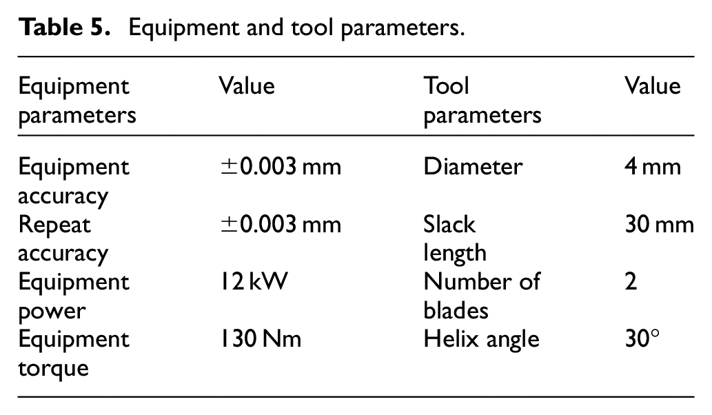
The experimental platform uses Jiangsu Heavy Road HD-V185F three-axis vertical machining center as shown in Figure 16 for milling experiment. The experimental material is 7050-T7451 aluminum alloy, the size is 200 mm × 180 mm × 15 mm. The cemented carbide ball head milling cutter is selected and the milling depth is 0.5 mm. The experimental equipment parameters and tool parameters are shown in Table 5. The experimental tool path is the dolphin-shaped trajectory in the above simulation. The maximum feed rate is 80 mm/s, the maximum acceleration is 800 mm/s2, the maximum jerk is 50,000 mm/s3, the maximum approximation error limit is 0.01 mm, the maximum chord error is 0.001 mm, and the sampling period is 0.5 ms. Milling effect is shown in Figure 17.
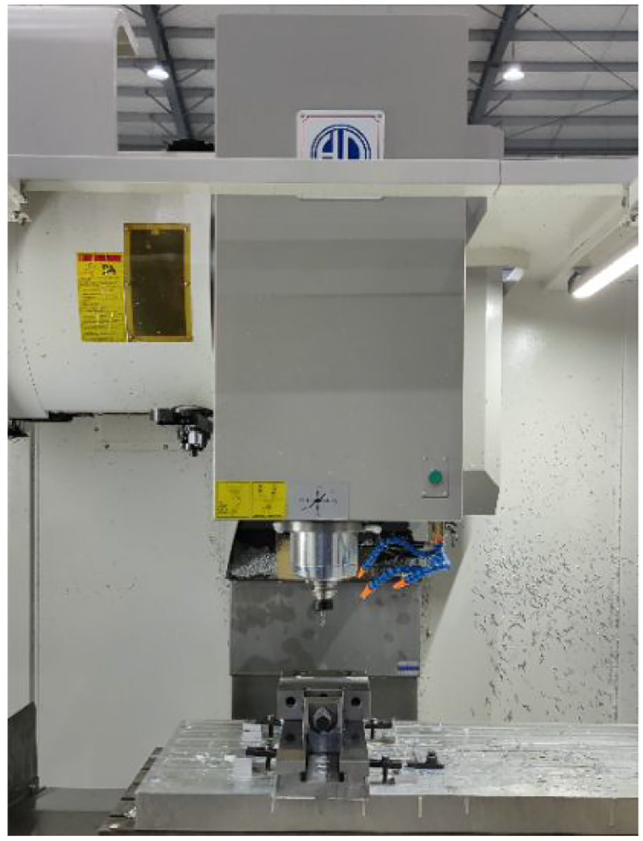
Experimental equipment diagram.
Equipment and tool parameters.
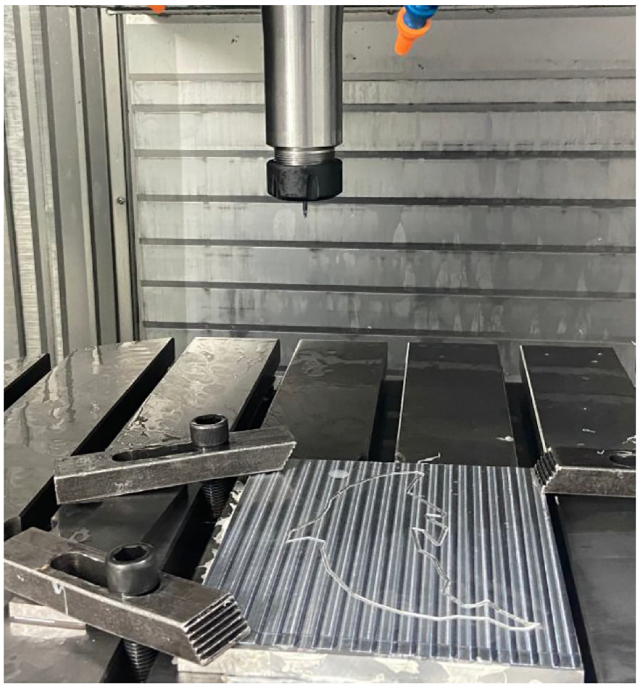
Processing effect diagram.
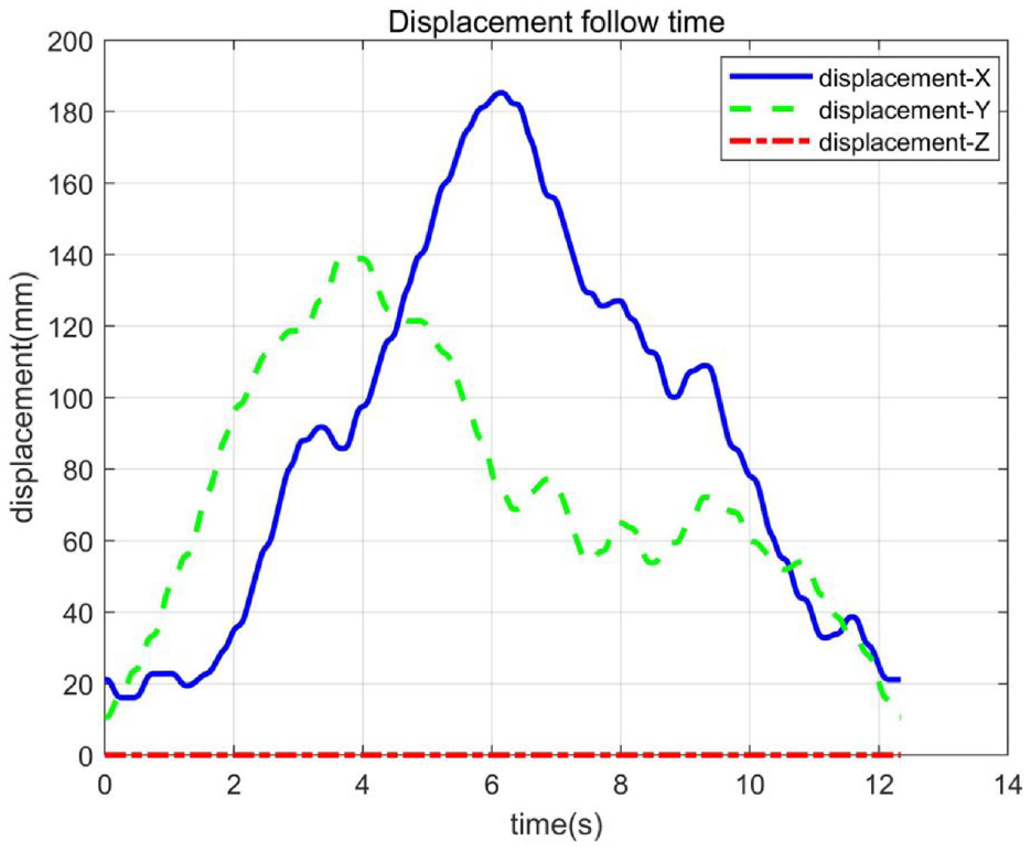
During the experiment, the interpolation command, synthetic speed and speed components of each axis can be obtained by upper machine interpolation. In order to further obtain the corresponding acceleration and jerk curves, the coordinates of the interpolation points need to be integrated according to the sampling period. The interpolation command in the machining process is shown in Figure 18, and the kinematic curve is shown in Figure 19. The blue, green, and red curves in Figure 18 represent the real-time interpolation commands of X, Y, and Z axes, respectively. Because the dolphin-shaped trajectory is planar, the real-time interpolation command of Z-axis in the processing is 0. It can be seen from Figure 19 that the velocity curve, acceleration curve, and jerk curve are smooth and continuous.
Interpolation commands.
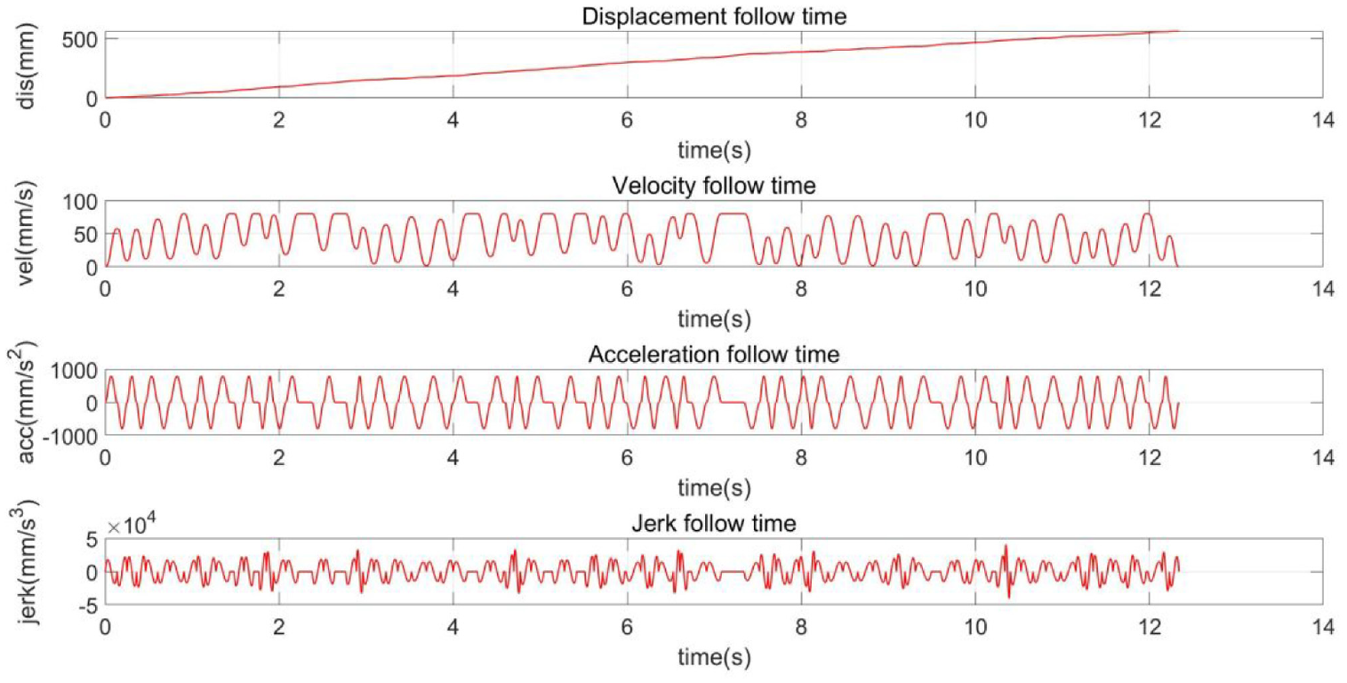
Kinematic curve.
The acceleration curves and jerk curves of each axis are shown in Figures 20 and 21. From the amplification diagram of the acceleration curve in Figure 20, the acceleration curves of each axis are continuous, and the maximum acceleration in actual processing is less than the maximum acceleration 800 mm/s2 set by the experiment. From the amplification diagram of the jerk curve of Figure 21, the jerk curves of each axis are continuous, and the maximum jerk is less than the maximum jerk 50,000 mm/s3 set by the experiment. This shows that the application of the corner smoothing and interpolation algorithm proposed in this paper in the real-time processing of the above experimental platform can ensure the smooth feed movement of the machine tool, reduce the vibration of the machine tool, and improve the processing quality of the parts.
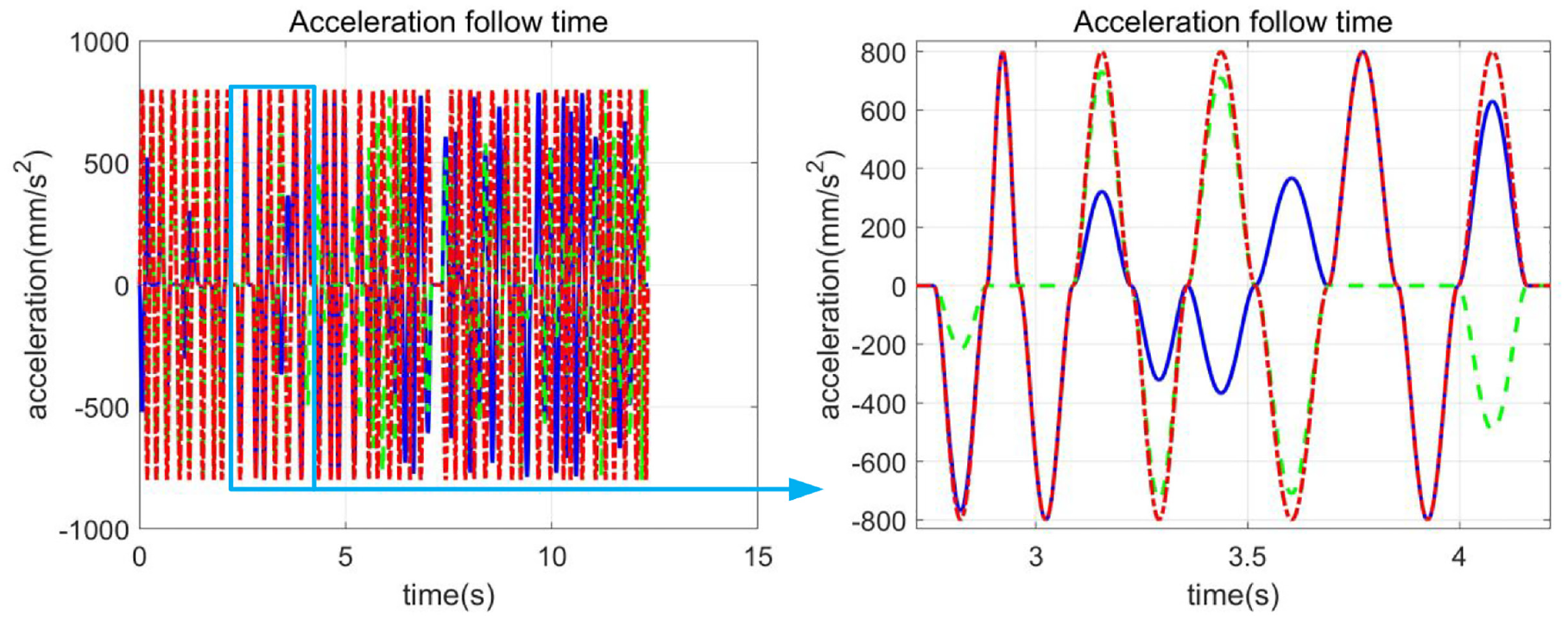
Acceleration curve of each axis.
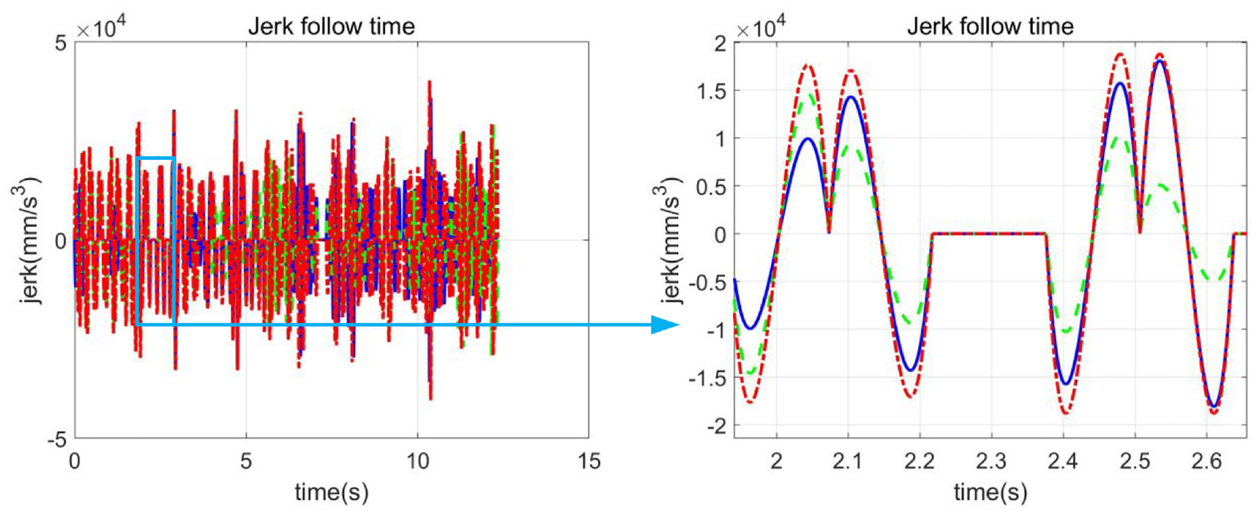
Jerk curve of each axis.
In order to further illustrate the performance of the proposed algorithm in the real-time CNC system, the G01 algorithm is integrated into the above open CNC system for comparative experiments. The experimental platform and simulation parameters are consistent with the above. The milling effect is shown in Figure 22. The left trajectory uses the G01 algorithm, and the right trajectory uses the interpolation algorithm in this paper. The test results of surface roughness are shown in Figure 23. By comparing the surface roughness values of the same test area on both sides, it can be seen that the average surface roughness of the proposed algorithm is better than that of the G01 algorithm. It is effectively verified that the algorithm in this paper improves the processing quality while ensuring the processing efficiency.
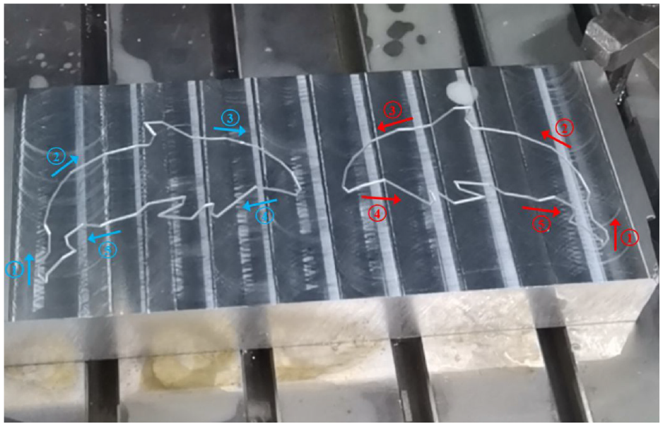
Processing effect comparison.
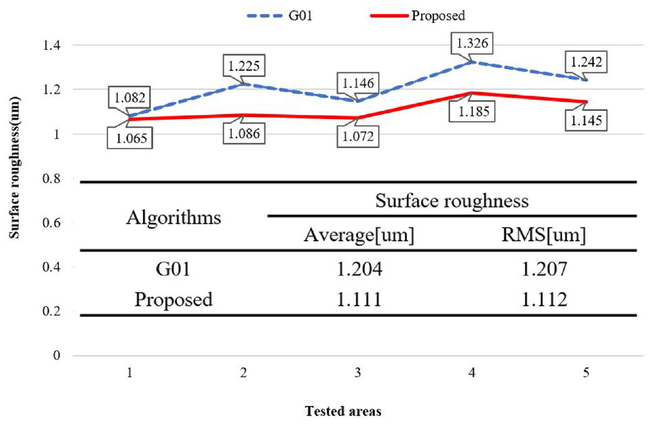
Comparison of surface roughness.
Conclusions
In NC machining, aiming at solving the problem of discontinuity at the corner of the linear tool path, a real-time corner smoothing and interpolation algorithm based on the C 3 continuous PH curve is proposed in this article, which realizes the continuous movement of tool axis jerk and improves the machining efficiency and quality of G01 tool path.
By inserting the constructed PH transition curve into the corner of the G01 path, the algorithm not only realizes the C 3 continuity of the tool path, but also ensures that the maximum approximation error of the corner smoothing is within the set error limit, which improves the computational efficiency and meets the real-time requirements of the CNC system.
Based on the corner smoothing algorithm and the flexible ACC/DEC control method, a real-time interpolation algorithm including unit division module, velocity planning module, and interpolation module is proposed to realize the continuous movement of tool axis jerk.
By comparing the simulation with the existing corner smoothing and interpolation methods, the superiority of the algorithm is verified from the control of the maximum approximation error, the real-time performance of the algorithm, the jerk fluctuation, and the processing efficiency.
By applying this algorithm to the real-time milling experiment of Jiangsu Heavy Road Vertical Machining Center, the effectiveness of the algorithm in this paper to realize the continuous motion of tool axis acceleration and jerk is verified.
Footnotes
Appendix 1
The detailed derivation process of equation (13).
Considering the symmetry of PH curve, the vector composed of control points is expressed as follows:
Therefore, the length of
The relationship between vectors
As shown in Figure A1, in the isosceles triangle composed of vectors
The relationship of angles is
Let
Appendix 2
The detailed derivation process of equation (14).
As shown in Figure 25,
Through equation (A1-1),
In Figure A2, it can be seen that
In
Therefore, combined with equations (A2-2) and (A2-3), the length relationship between
Appendix 3
Declaration of conflicting interests
The author(s) declared no potential conflicts of interest with respect to the research, authorship, and/or publication of this article.
Funding
The author(s) disclosed receipt of the following financial support for the research, authorship, and/or publication of this article: The research is sponsored by the National Natural Science Foundation of China (No. 51775328).