
Abstract
In turning operations, vibration is a significant problem that leads to an imperfect surface, cutting tool damage, and unstable production. Vibration affects not only the workpiece’s surface quality, but also the cutting tool life, and ultimately the overall process cost. Since Shape Memory Alloys (SMA) has a very high vibration damping capacity, the effect of using TiNi3 alloy as the turning tool holder material is investigated in this paper. The tool holder vibrations are investigated analytically and numerically in both external and internal turning operations. The analytical study utilizes the Laplace Transformation Method to find the natural frequency and the beam’s displacement as a function of time and the longitudinal axis. The numerical study is performed using transient and Modal Analysis using ANSYS software. A comparison of the analytical and numerical results shows that they were very close to each other. The numerical study shows that TiNi3 alloy decreases vibration amplitude and acceleration for external and internal turning operations. It is shown that the use of TiNi3 alloy in the turning cutting tools decrease the vibration acceleration amplitudes by 43.1% and 40.2% for internal and external turning operations, respectively. Additional improvement in the performance of the internal turning cutting tool is achieved by presenting a new model of the boring bar that depends on the integrating of TiNi3 alloy and carbide material. Optimization of five steps is made to obtain the optimal design of the presented model. The new model shows that the optimized boring bar decreases the vibration acceleration by 60.2% compared to the commercial boring bar. Therefore we strongly recommend it for manufacturing turning tool holders.
Introduction
Today, the industry relies heavily on different machining processes such as turning and milling. Vibration is one of the most important problems encountered in machining operations that affect the quality of the product, the life of the cutting tools, and, therefore, the overall operation cost. The self-excited vibration in the machining operations, known as chatter, is one of the main problems affecting the metal removal rates. 1 In recent decades, researchers have paid much attention to the chatter vibration, and there have been many studies that provided solutions to this phenomenon. These solutions can be classified into two main approaches:
The first approach focuses on the idea that chatter can be prevented by the use of a Stability Lobe Diagram (SLD) by changing cutting parameters (depth of cut, spindle speed, and cutting speed). 2 However, the control of the cutting parameters and cutting conditions can be suppressed chatter. Tunç and Budak 3 have studied the effect of cutting conditions and cutting tool geometry on process damping in turning and milling operations. They had concluded that lower cutting speed, higher hone radius, the increase in total contact length between the tool and the material, and cylindrical flank geometry causes more process damping and lead to more stability in machining operations. Mahdavinejad 4 presented an instability analysis of the turning operation using finite element analysis. Dynamic modeling has been made of the turning machine. The stability lobe diagram is plotted according to the obtained results. In a recent study by Qiu and Ge, 5 they presented an improved method to predict chatter vibration in turning operations by width-distance lobe instead of the previous width-speed lobe. This approach helped predict chatter in the radial turning regardless of workload, skill requirements, and time consumption. Preventing chatter from occurrence by using stability lobe diagrams remains ineffective when high activity is required.
In addition, chatter can be suppressed by monitoring the process using different sensors and then selecting optimal cutting parameters that lead to less vibration and high surface quality. Kuntoğlu et al. 6 presented a review on sensors and signal processing systems in milling and turning operations. They concluded that sensor-based systems might provide reliable information to monitor cutting conditions. Therefore, they select the cutting parameters that protect the tool from failure and the workpiece from poor quality. In a recent study, to obtain the best values of cutting parameters in turning of AISI 5140, five different sensors were integrated into a lathe for online data acquisition, in addition to online measurements of surface roughness and tool vibration, 7 these sensors (which consider as indirect tool condition monitoring systems 8 ) were: cutting force, acoustic emission, tooltip temperature, tool vibration, and motor current. The results show that dynamometer and acoustic emission sensors can be considered the most reliable sensors.
The second approach is based on the idea that the cutting process can be stabilized using different kinds of process damping. There are three kinds of damping techniques for suppressing chatter in literature: passive, semi-active, and active. The objective of Passive solutions is to increase the cutting process’ damping without any external power supply for dissipating the vibration energy. Passive auxiliary systems can dissipate mechanical energy (like friction dampers,9,10 impact dampers, 11 and tuned mass dampers TMD12,13) and the application of unique materials. 14 Many studies have presented different kinds of passive dampers. Chatter can be suppressed in the boring process by using a passive damper made of Cartridge brass (30% Zn and 70% Cu) placed on the boring bar. 15 The turning system’s two degrees of freedom model can be used to investigate the effect of process damping on chatter amplitude and frequency changes occurring in the turning operations. 16 A three-element type of vibration absorber embedded in the cutting tool was presented by Yang et al. 17 and achieved an 87.1% reduction in the amplitude of the target mode.
The boundary of the nonlinear tuned vibration absorbers (NLTVA) and the safe, unsafe, and unacceptable operations according to NLTVA parameters is presented by Detroux et al. 18 Waydande et al. 19 presented the study of implemented passive damping design using viscoelastic composite materials for internal turning. The obtained tool resulted as an efficient tool that can be used in the high material removal rate conditions over a relatively wide range of cutting parameters. Many studies were focused on the foundation of the optimal values of TMD parameters to achieve more stability of the cutting process.20–22 The stability of peripheral milling has been studied using a tunable vibration absorber, and the optimum values of absorber’s parameters have been determined by Moradi et al. 23 It was shown that these kinds of absorbers are robust against the uncertainties of the dynamic model.
Active damping methods uses sensors and actuators to observe vibrations and suppress them in real-time during cutting operations. The most used technologies in active damping systems are electromagnetic and piezoelectric actuators.24,25 Using a piezoelectric actuator and eddy sensor, which allows observing and modeling machining parameters, an active controller for chatter suppression in turning operations was presented by Ma et al. 26 This controller can attenuate the chatter and also enlarge the stable SLD region. Munoa et al. 27 developed a biaxial actuator to suppress chatter vibrations of heavy-duty operations in ram-type milling machines. It has been shown that the chatter limit is enlarged enough by using this active biaxial actuator. A recent active boring bar was presented to control the chatter vibrations in internal turning operations using adaptive inverse control. 28
Semi-active damping devices are mostly passive devices tuned in real-time, but they cannot introduce a controlled damping force. 29 A semi-active damper depends on the magnetorheological (MR) damping effect of reducing the workpiece’s surface roughness in milling operations. 30 MR damper incorporates Magnetorheological fluid features, which uses the input current to modify the magnetic field to improve the variable stiffness and produce a damping effect. Aguirre et al. 31 produced a self-tuning semi-active tuned-mass damper for suppressing chatter in the milling operations. This damper depends on automatic detection of the primary vibration frequency by accelerometers embedded in the damper. It was concluded that a robust implementation solution suitable for industrial use is still missing.
On the one hand, using active dampers is difficult and expensive because sensors recognize chatter vibrations and actuators to produce forces damping cutting vibrations. On the other hand, passive dampers (by adding tuning mass) and semi-active dampers are not very complex, but accurate tuning is still challenging. The control of the damper tuning requires changing of – at least – the natural frequency of the damper.
Mainly metals 32 and polymers 33 are used for vibration damping due to their viscoelastic character. The microstructure significantly affects the damping capacity of a material. 34 The shape-memory property of the material refers to the ability of the material to transform to a phase that has a twinned microstructure so that the material can return to its initial shape when heated.
In the SMA, a large amount of hysteresis between loading and unloading phases means that a significant part of the stress energy is wasted as heat. This power dissipation provides a damping function as well. This grants SMA an excellent damping capacity. 14
Several studies have recently presented the effect of vibrations on the cutting tool in turning operations and how to reduce these vibrations to get better performance. Some of these studies have focused on adding materials that have vibration-damping properties to the cutting tool, such as carbon fiber, 35 polyurethane, nitride-butadiene rubber and butyl rubber, 36 or foamed aluminum. 37 Impact dampers have also been used to dampen vibration in the boring bar by adding a double copper damper to the cutting tool. 38 A new type of impact damper was used by including the different sizes of steel spheres into the boring bar, 39 and it has been concluded that by increasing the size of the steel spheres, the impact damper’s performance improves. In the study presented by Ghorbani et al., 40 several models of the boring bars were studied. These models experimented with adding epoxy granite as a composite material, rubble as filler material, and fine powder made of high strength granite.
The use of shape memory alloy in vibration suppression is limited to construction, and civil engineering uses. This paper highlights the use of this alloy to reduce vibration in the cutting tool during turning operations. This paper aims to produce a new boring bar model depending on the SMA and carbide properties to reduce vibrations in the turning process. For this purpose, an analytical study was conducted on a cutting tool as a simple cantilever beam to calculate natural frequencies and find vibration mode shapes. In the second step, numerical models of the turning cutting tools were produced. The validity of these models was confirmed by comparing the results of the analytical and numerical studies. In the third step, the boring bar model was optimized to get an optimal model. Finally, the effectiveness of the proposed new boring bar model was verified by comparing the vibrations of the new boring bar and the commercial one.
Three advantages characterize this paper’s work: (1) We used actual turning forces data, taken from the previous experimental studies in the analytical research, to obtain near actual results. (2) We developed a new model for a boring bar that depends on integrating carbide material and TiNi3 alloy as a type of shape memory alloy. (3) We ran an optimization procedure with several steps of the proposed model to minimize the boring bar’s vibrations to improve the cutting tool’s performance.
Material and methods
Analytical study
The tool holder in turning operations can be considered a cantilever beam because it is fixed from one end and exposed to the cutting forces at the other end, as shown in Figure 1. The cutting force effects at the edge of the cutting insert, but according to physical principles, the force can be moved to the edge of the beam. In this paper, the Laplace transform method was used to find the displacement at the free end of the cantilever beam. Laplace transform is a method used frequently by engineers. By applying this method, an ordinary differential equation can be changed into an algebraic equation since an algebraic equation is generally easier to deal with.
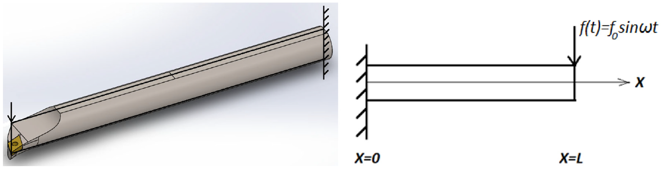
Turning tool holder as a cantilever beam.
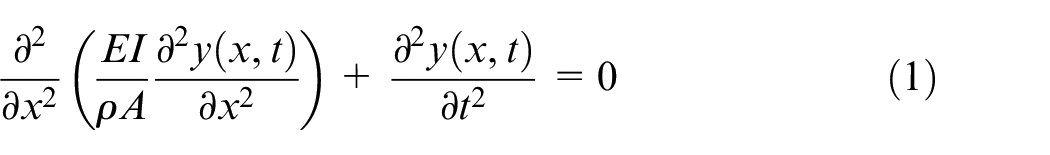
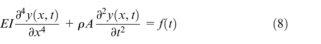
For the free vibration, the equation of motion of a cantilever beam can be written as 41 :
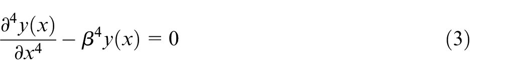
In the free vibration,

So equation (1) returns to normal differential equation:
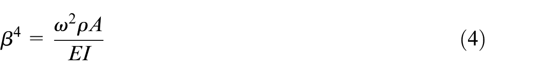
By taking Laplace transform of equation (3):
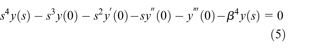
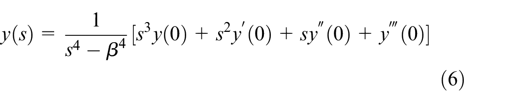
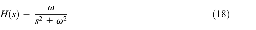
Where
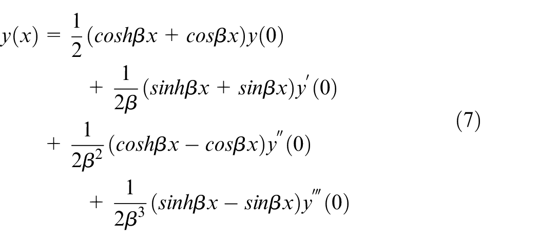
Applying Inverse Laplace transform to equation (6) results in:
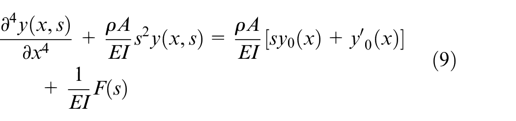
The governing equation for the forced vibration is given by:
Where
or
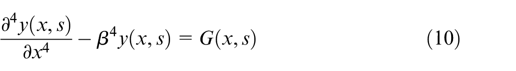
Where:
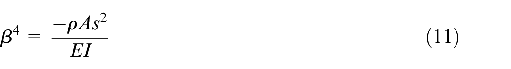
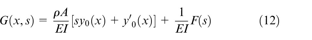
By applying Laplace transform to equation (10) in respect to x and considering p as the subsidiary variable, we obtain
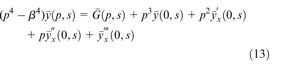
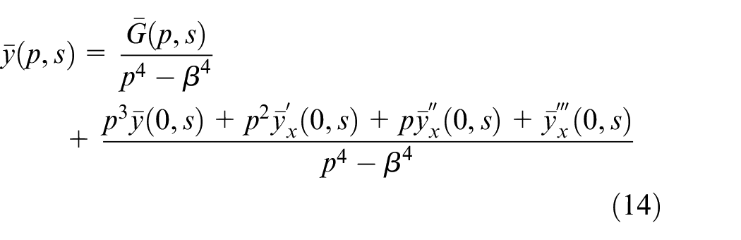
where
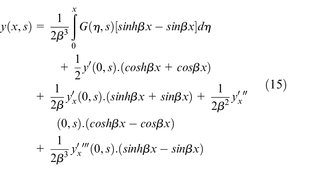
To find the solution
The cantilever beam is subjected to a concentrated force
The boundary conditions of the studied beam:
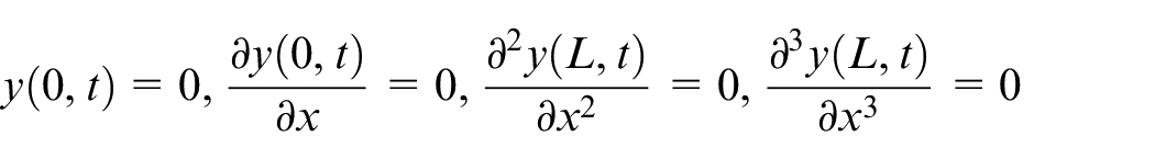
Boundary conditions can be written as (By taking Laplace transforms):

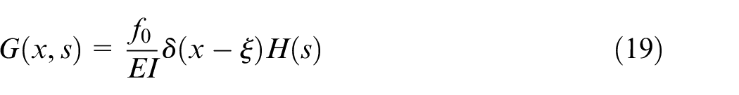
The applied concentrated force can be expressed as:

Laplace transform of equation (16) results in:

Where
By considering the initial conditions:
Using the boundary conditions at x = 0 and equation (19), equation (15) can be expressed as:
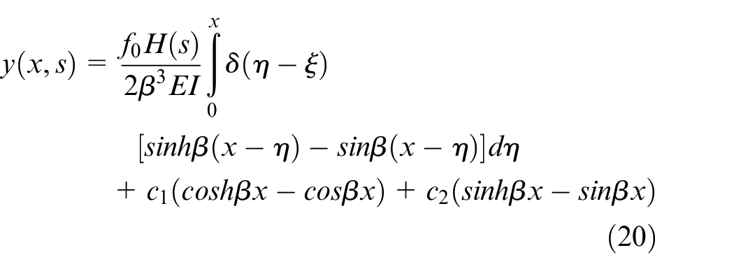
Where:
By differentiating
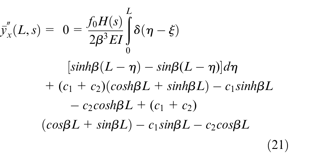
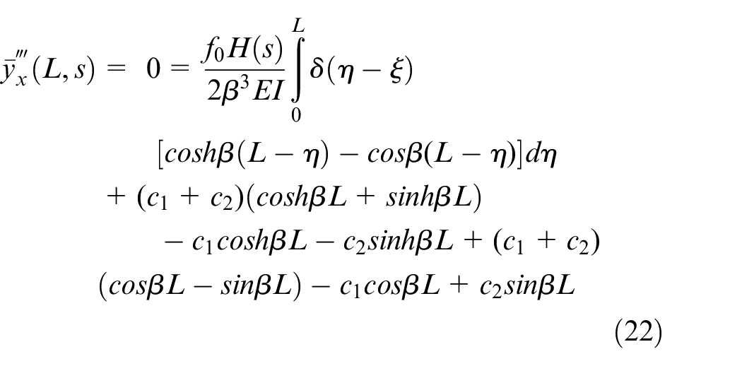
The solution of equations (21), (22) results in:
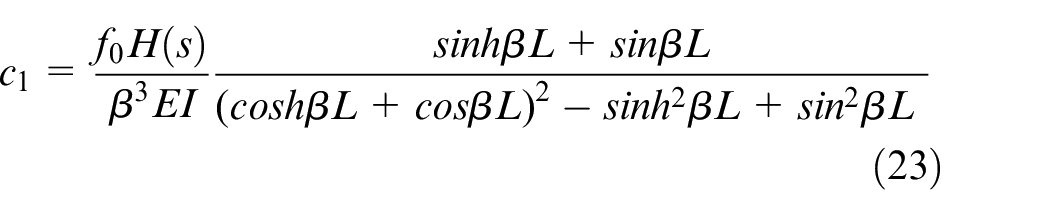
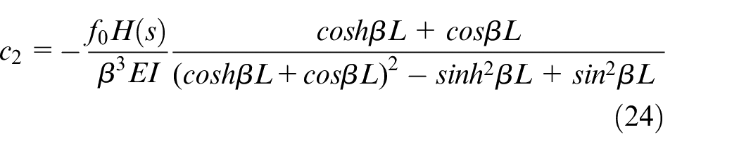
Thus, equation (20) becomes:
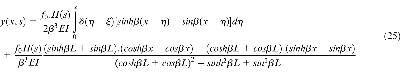
Finally, we take the inverse Laplace transform of equation (24) in respect to t to find the displacement of the beam as a function of
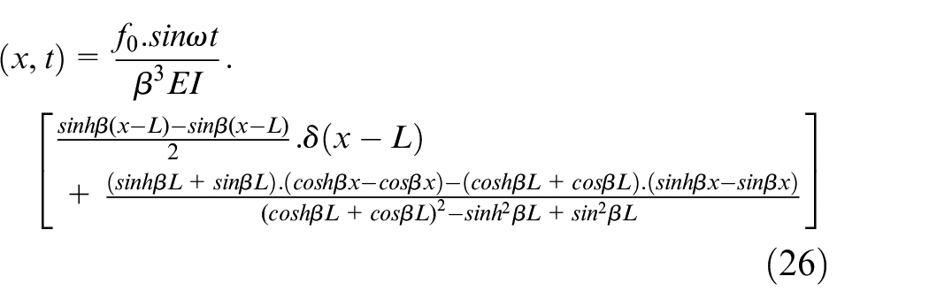
The value of
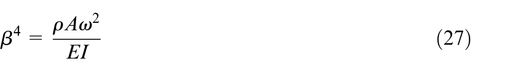
The natural frequencies can be obtained from:
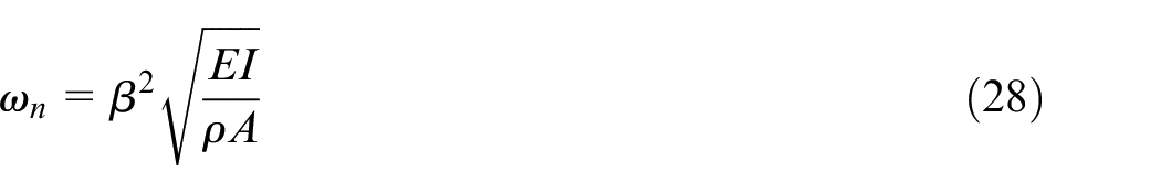

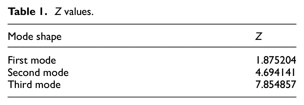
For the studied cantilever beam, the values of
Z values.
The first three shape modes are shown in Figure 2.

Analytical vibration mode shapes.
The force-time data measured in the previous experiment during turning operation is applied to the cantilever beam to obtain near-to-real results. The applied force-time graph is shown in Figure 3.
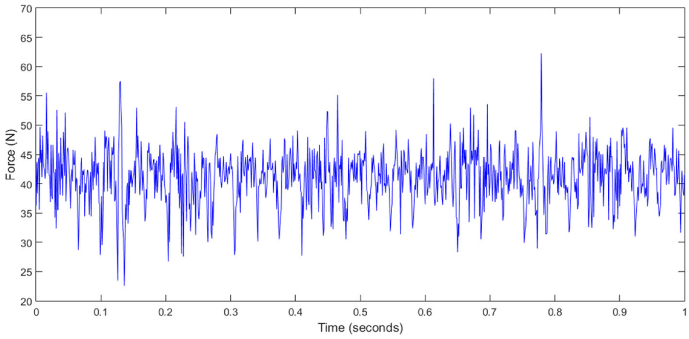
The applied force-time graph in the analytical study.
The results of the analytical study (displacement-time and acceleration-time graphs) are shown in Figure 4.
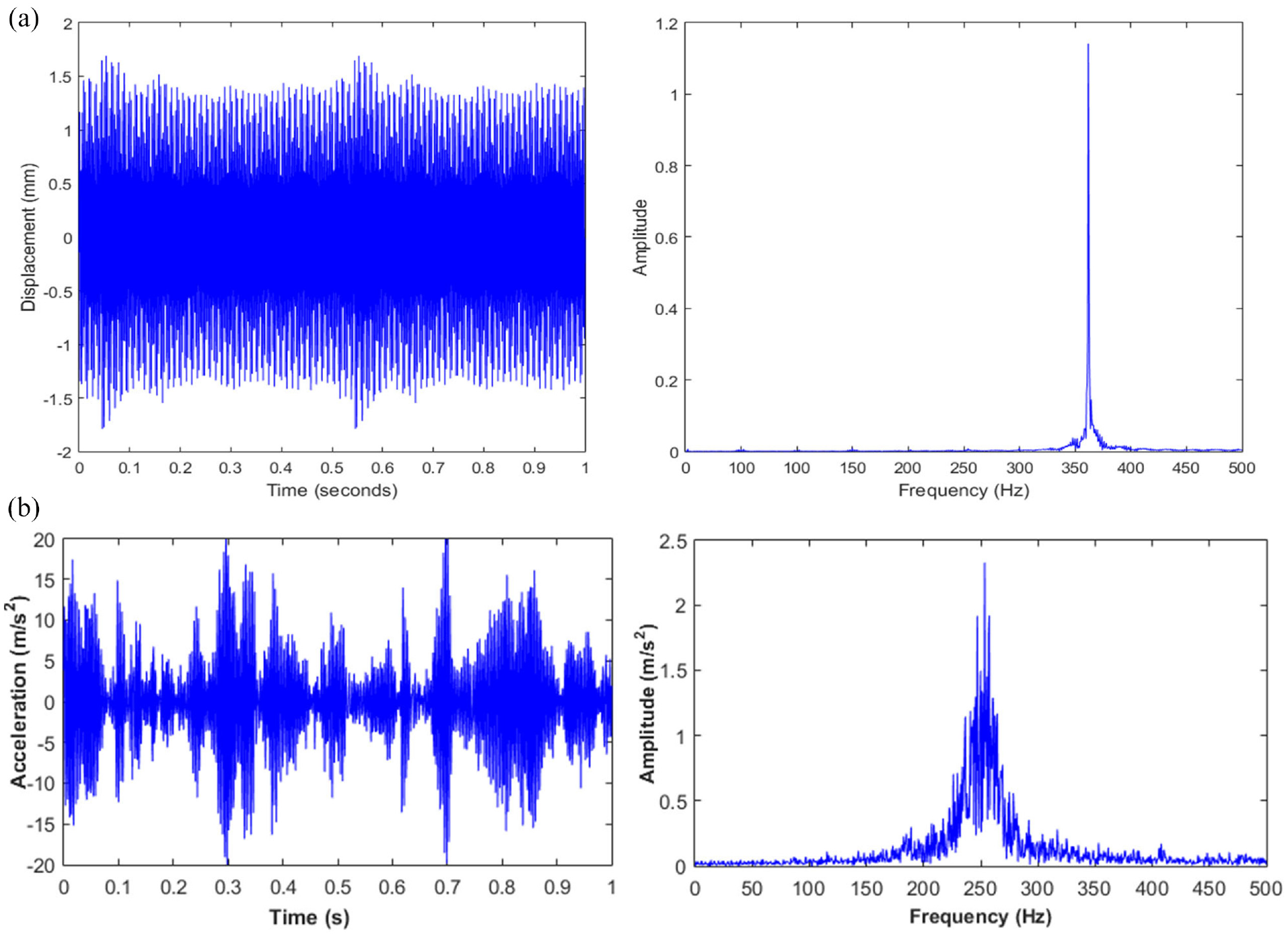
Analytical results of prismatic tool holder: (a) displacement-time and frequency spectrum graphs, (b) acceleration-time and frequency spectrum graphs.
Numerical study
The numerical study was conducted to compare the numerical and analytical study results and test the validation of the produced numerical model planned to be used later in this research. In this study, transient and modal analysis was made using ANSYS software. Cubic element with eight nodes was used in FEM analysis. This type of element is suitable for prismatic and cylindrical shapes. The mesh model consists of 46,521 nodes and 10,000 elements.
The force data, measured by the dynamometer from the previous experiments, were applied as tubular data in ANSYS. Figure 5 shows the boundary conditions and the applied forces for prismatic and cylindrical beams. The boundary conditions were taken similar to the analytical study (as a cantilever beam), constrained at one side and the force applied at the middle of the other side, as shown in Figure 5. Modal analysis was made to obtain the mode shapes and the natural frequencies of the prismatic and cylindrical beam. Furthermore, acceleration-time graphs were obtained from Transient Analysis. The mode shapes of the prismatic and cylindrical beams, which were obtained from the ANSYS modal analysis, were presented in Figure 6. These shapes correspond to the mod shapes resulting in the analytical study shown in Figure 2.
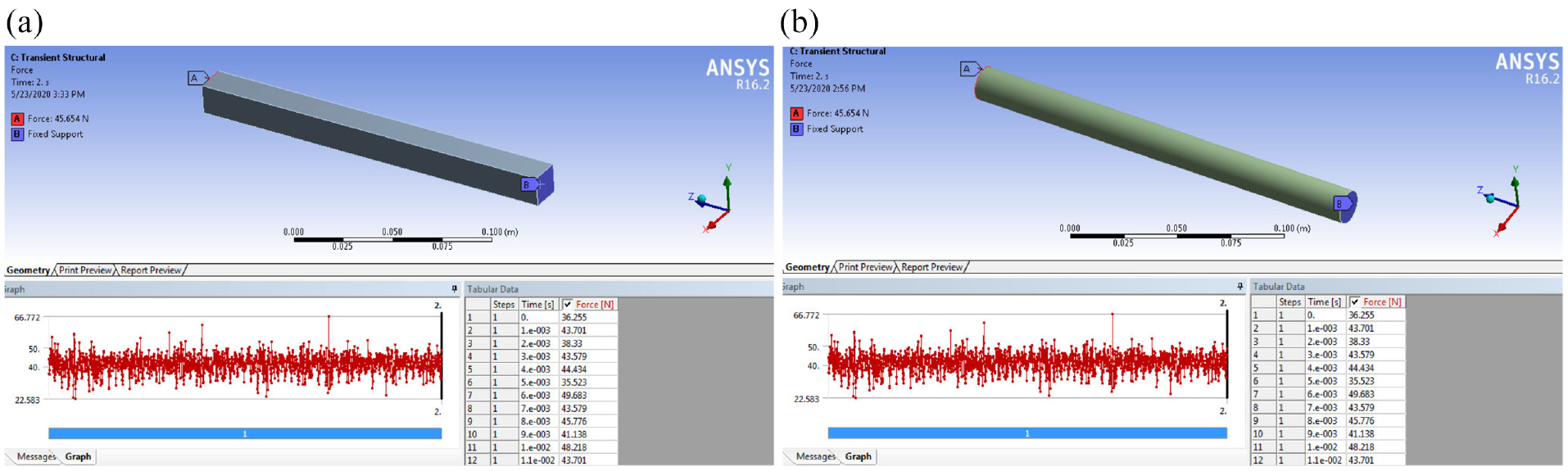
The boundary conditions and the applied force of: (a) prismatic beam, (b) cylindrical beam.
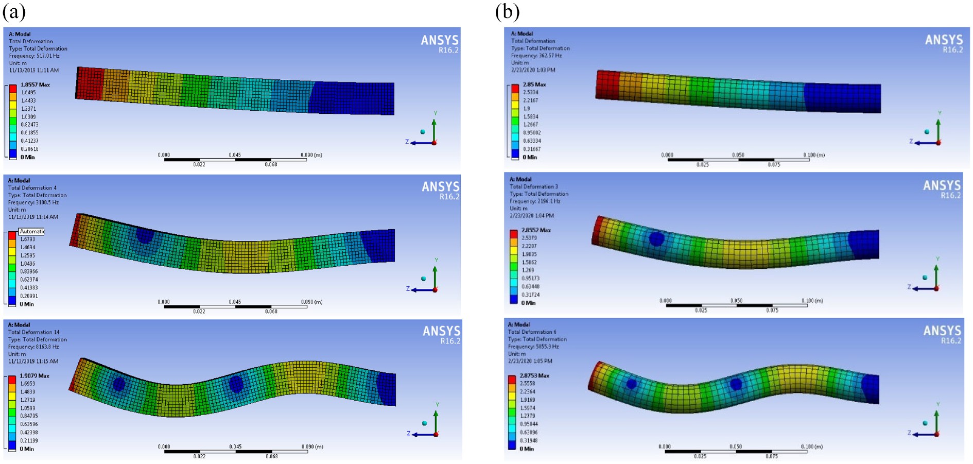
Mode shapes of (a) prismatic beam, (b) cylindrical beam.
The proposed new model of boring bar
By taking advantage of the models presented by Ghorbani et al., 40 and the properties of SMA’s in damping vibrations, a new model based on the integration of TiNi3 alloy and carbide material is introduced to reduce the vibrations in the boring bar. The primary new model consists of a boring bar (of TiNi3 alloy), two carbide plates at the top and bottom of the bar, and a carbide core placed in the boring bar’s center, as shown in Figure 7. In order to increase the boring bar’s damping capability, a passive damping mechanism is used by applying a material with high damping capability (TiNi3) in the boring bar’s structure to dissipate extra vibration energy.
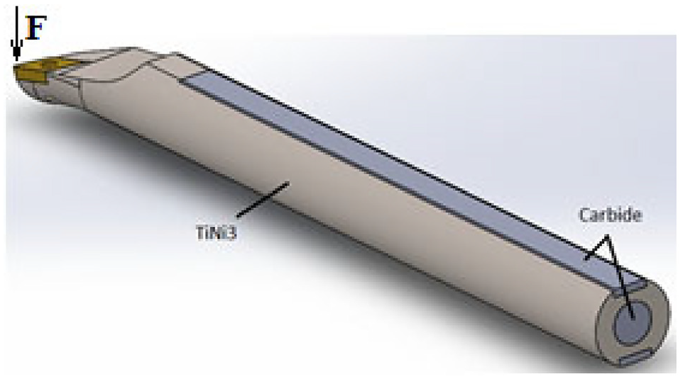
The proposed primary model.
Optimization method
An optimization study was run to determine the best design that leads to a lower vibration in the boring bar. ANSYS program has been used to do the optimization procedure.
In this study, the Screening optimization method is used to find the boring bar’s optimal design. The screening optimization method is a simple method based on sampling and sorting algorithms. It requires little amount of time and gives quick results, and is relatively accurate. The method runs by generating 1000 samples, then searching to find three optimal candidates, and it ultimately converges after 1000 evaluations. Figure 8 illustrates the scheme of this optimization method.
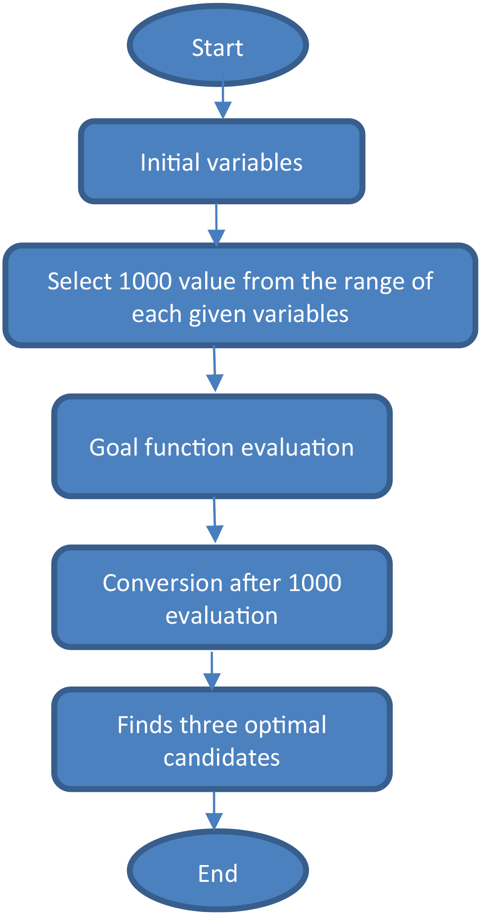
Scheme of the screening optimization procedure.
Five optimization steps were passed to reach the final optimal design. In all steps, the optimization goal was to minimize acceleration amplitude in the transient Analysis. In every optimization step, a single force (F = 100 N) was applied to the side of the cutting tool, as shown in Figure 7. In order to confirm the results obtained from the optimization steps, numerical models were made and analyzed according to each optimization step’s results.
Results and discussion
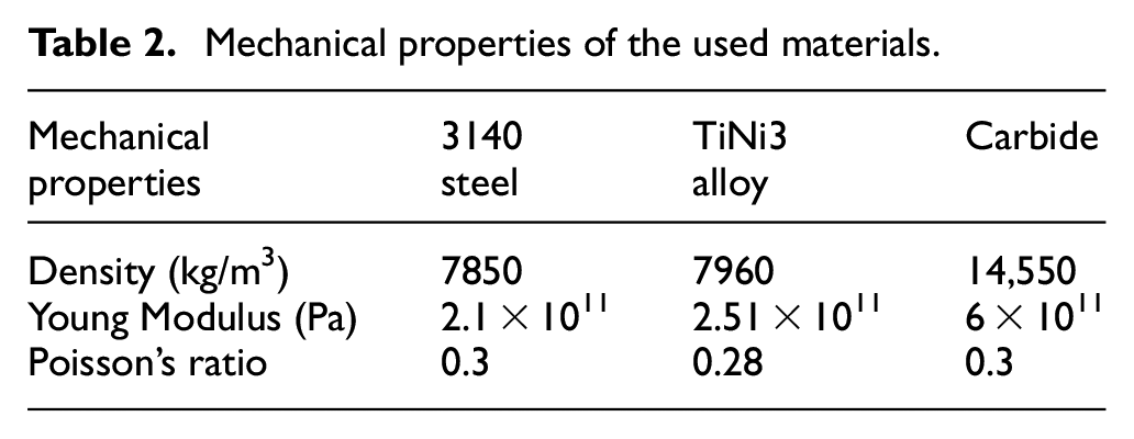
The numerical and analytical studies covered two kinds of materials and two kinds of cantilever beams. Both cylindrical (internal turning case) and prismatic (external turning case) cantilever beams were studied. The cylindrical beams have a diameter of 16 mm and a length of 200 mm, while the prismatic one has a square-shaped cross-section with a 16 × 16 mm area, and its length is 200 mm. The free vibrations of prismatic and cylindrical cantilever beams were first examined to determine the conformity of the analytical and numerical results. Two kinds of material were studied, 3140 steel and TiNi3 alloy. The mechanical properties of the used materials are shown in Table 2.
Mechanical properties of the used materials.
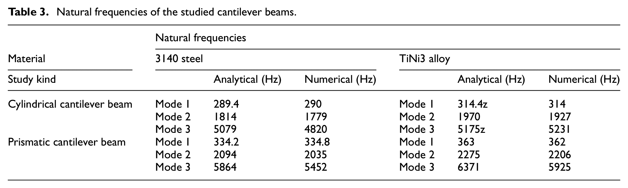
Natural frequencies were obtained for free vibrations of the prismatic and cylindrical beam. The natural frequencies obtained analytically and numerically for all cantilever beams are shown in Table 3. As we can be seen, there is a perfect alignment between the two studies in the first mode, and the error ratio increases as the mode number increases. These increases are due to two reasons: (1) The cantilever beam is considered two dimensional in the analytical study and three dimensional in the numerical analysis, (2) the mesh quality affects the numerical results significantly. Furthermore, the natural frequencies of the beam made of TiNi3 alloy are less than that made of 3140 steel because of the phase transformation in the structure of SMA.
Natural frequencies of the studied cantilever beams.
Acceleration-Time and Amplitude-Frequency spectrum graphs were obtained using analytical and numerical methods to validate the presented numerical model. Figure 9 shows the comparison between the Acceleration-Time graphs and Acceleration Amplitude-Frequency graphs of numerical and analytical studies for both prismatic and cylindrical steel cantilever beams. For the prismatic cantilever beam, the RMS value of the analytical study is 61.4 and of the numerical study is 61.9. For the cylindrical cantilever beam, the RMS value of the analytical study is 26.9 and of the numerical study is 27.2. Looking at all graphs in Figure 9 and RMS values, it can be said that the analytical and the numerical study are very close to each other.
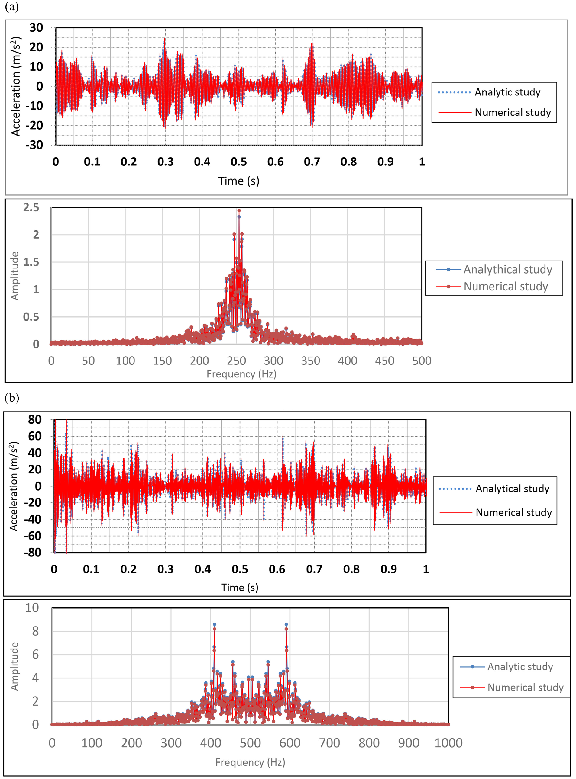
Comparison between analytical and numerical studies; (a) prismatic steel cantilever beam (b) cylindrical steel cantilever beam.
After validating the presented numerical model by comparing the analytical and numerical results for both free and forced vibrations of the external and internal turning cutting tools, the amplitude of the forced vibrations was found numerically for prismatic and cylindrical tool holders made of three different materials.
Figure 10 shows the comparison of the Acceleration-Time graphs and the Acceleration Amplitude-Frequency spectrum graphs for different kinds of materials (3140 steel, TiNi3 alloy, and carbide).
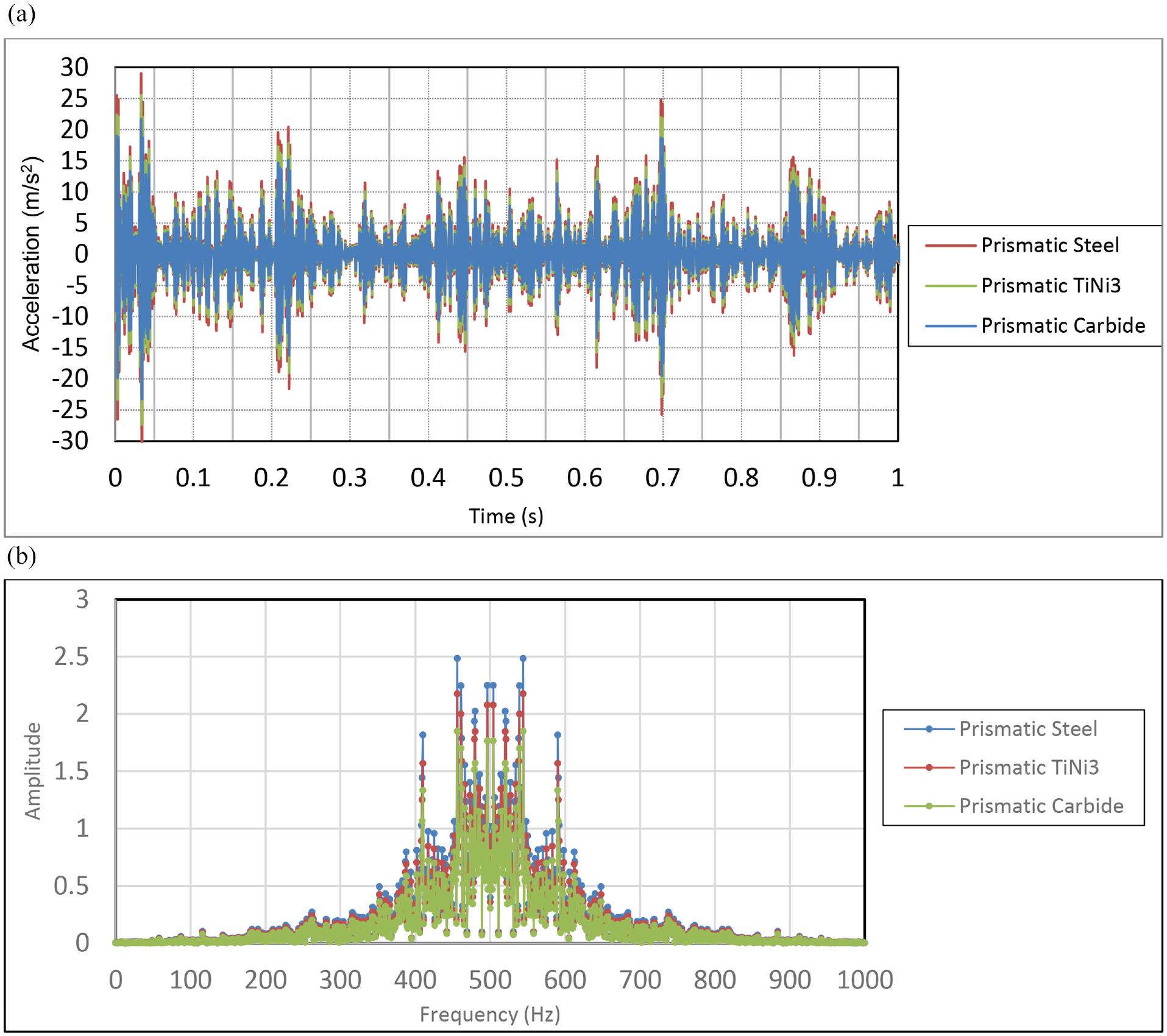
Comparison between (a) Acceleration-Time graphs (b) Acceleration Amplitude-Frequency spectrum graphs for different materials of prismatic model.
Table 4 shows the RMS values of the accelerations of these prismatic beams. Carbide makes the RMS value of the accelerations about 7% less than TiNi3 Alloy and about 43.3% less than the steel one. It is clear from Figure 10 and Table 4 that when the beam’s material is carbide, the beam will vibrate with lower vibration amplitude.
RMS values of the vibration acceleration of prismatic models.
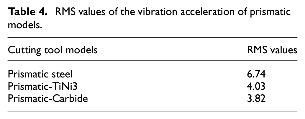
Figure 11 shows a comparison between the Acceleration-Time graphs and the Acceleration Amplitude-Frequency spectrum graphs for the presented primary model of the boring bar and the standard boring bar with different materials.
Comparison between (a) acceleration-time graphs (b) acceleration amplitude-frequency spectrum graphs for different cylindrical models.
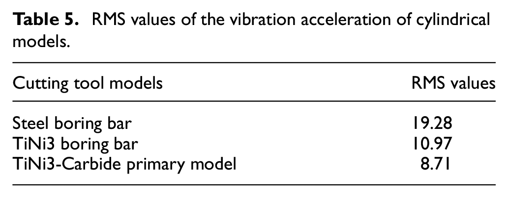
Table 5 shows the RMS values of all boring bars accelerations. TiNi3 alloy has an RMS value of the boring bar’s accelerations about 43.1% less than steel. Looking at the RMS values, it is clear that the vibration acceleration amplitude is decreased by 54.8% for the presented primary model because it contains a combination of carbide and TiNi3 alloy.
RMS values of the vibration acceleration of cylindrical models.
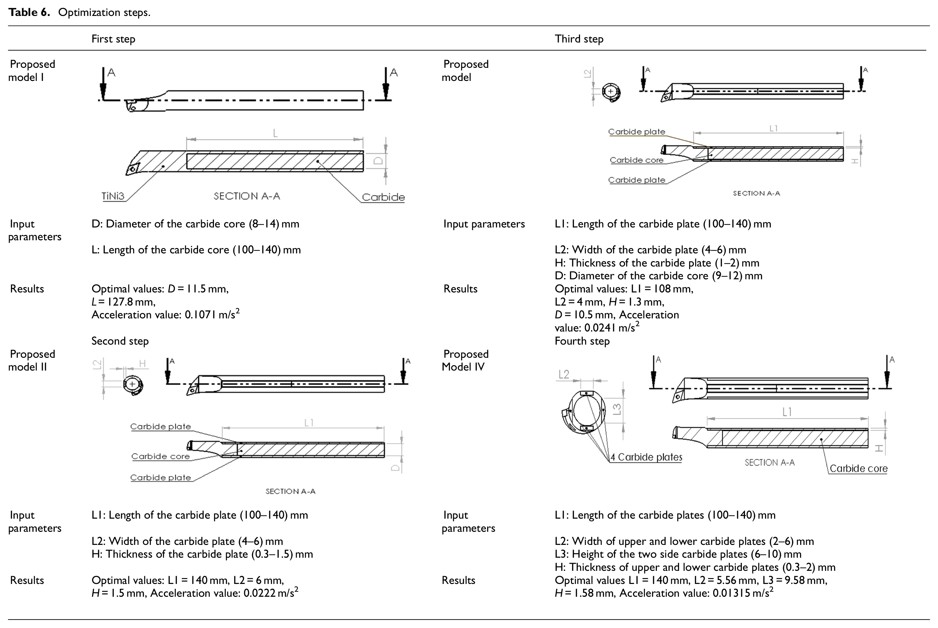
After determining that using TiNi3 and carbide materials in turning cutting tools has reduced the turning tool vibrations, we decided to use those two materials to design a new vibration-reduced boring bar. The optimization steps were performed using the numerical analysis method (ANSYS R16.2) to find the optimal design and the optimal dimensions of the boring bar that lead to a minimum vibration level. The presented models, input parameters and ranges, and results of all optimization steps are shown in Tables 6 and 7.
Optimization steps.
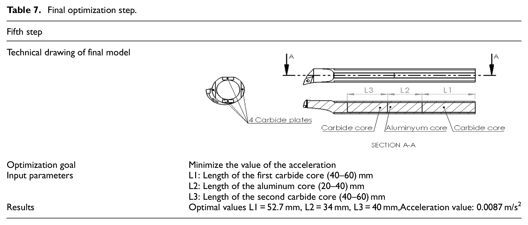
Final optimization step.
Given the general case of damper design, there should be a mass of significant weight inside the damper to increase the model’s stiffness. 40 Therefore, since carbide is a high-density material, a cylindrical core of carbide material was placed in the boring bar’s center in the first optimization step. The diameter and the length of the cylindrical core are taken as parameters (the maximum and minimum values are shown in Tables 6 and 7). The optimization goal is to reduce the vibration acceleration of the cutting tool. As a result, the optimal diameter and the optimal length of the cylindrical core were 11.5 and 127.8 mm, respectively. In the second step, it was assumed that the best dimensions of the cylindrical core found in the first step were constant. Two plates of carbide material were placed on the top and bottom of the cutting tool. In this step, optimization was made to determine the dimensions of these two plates. We found in this step that the plates’ best dimensions were the upper limits specified in the input parameters. This situation shows that the plates on the cutting tool greatly influence the tool’s vibration. In the third step of the optimization, the core’s diameter inside the cutting tool was released (so that the thickness of the plates becomes greater when the diameter of the core is smaller). Therefore, optimization was performed to find the best dimensions for both core and plates in this step. As a result, the minimum acceleration values in the second and third steps were very close. The second step is slightly smaller, so optimization is continued depending on the second step results.
In the previous optimization steps, it was demonstrated that those plates were essential to improve the performance of the cutting tool, therefore, in the fourth step of optimization, two more plates were placed vertically on both sides of the boring bar (Table 6), and the optimization was carried out to determine the dimensions of both vertical and horizontal plates. This step considered the cylindrical core’s diameter and length are constants (11.5 mm in diameter and 127.8 mm in length). The optimal dimensions are as follows: the length of the plates 140 mm, the width of upper and lower plates 5.56 mm, the thickness of upper and lower plates 1.58 mm, the height of vertical plates 9.58 mm. In the fifth step of optimization, two-cylindrical cores of carbide material are placed side to side, and a cylindrical core made of damping material is placed between them (Table 6). A boring bar with a constrained layer damper was used by Song et al. as a foamed aluminum material was used as a damping material to improve the stability of the internal turning process. 37 In this study, foamed aluminum material was used for the central core as a damped material. The diameters of the cores were set according to the first optimization step (11.5 mm). Optimization was made to determine the lengths of the three cores. As a result, the optimal length of the first carbide core was found to be 52.7 mm, the optimal length of the foamed aluminum core at 34 mm, and the optimal length of the second carbide core at 40 mm. Transient analysis was made for each optimization step, and the acceleration-time and FFT graphs are shown in Figure 12.
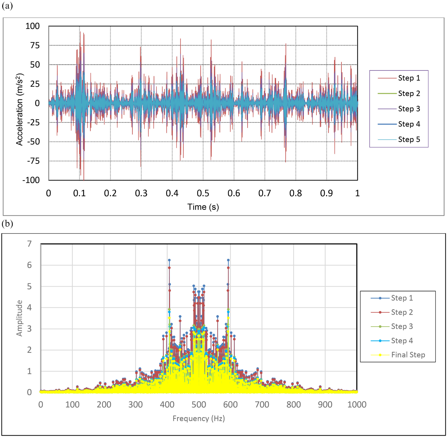
(a) Acceleration-time graphs (b) Acceleration FFT graphs for all optimization steps.
It is clear from Figure 12 that the boring bar’s vibration acceleration decrease with the progression of the optimization steps. These graphs prove that the progression of the optimization steps is on the right path. A numerical analysis was run on this model by applying the cutting forces presented in Figure 3 to verify the last model reached in the optimization procedure.
The acceleration-time graph was generated for two finite element models to determine the effect of finite element size on the numerical results. The first model consists of 6336 elements and the second model consists of 84,504 elements. Comparison between acceleration-time graphs of these two models is shown in Figure 13. Vibration amplitudes in the two graphs seem to be close, so we can say that the finite element size does not affect the numerical results.
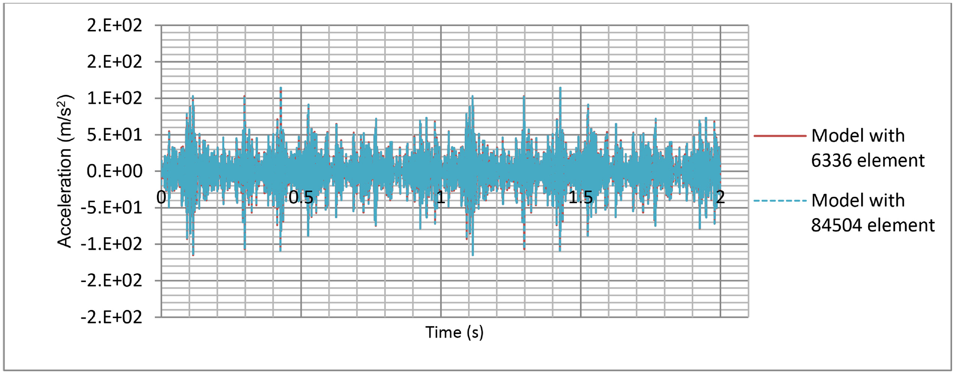
Effect of finite element size on the numerical results.
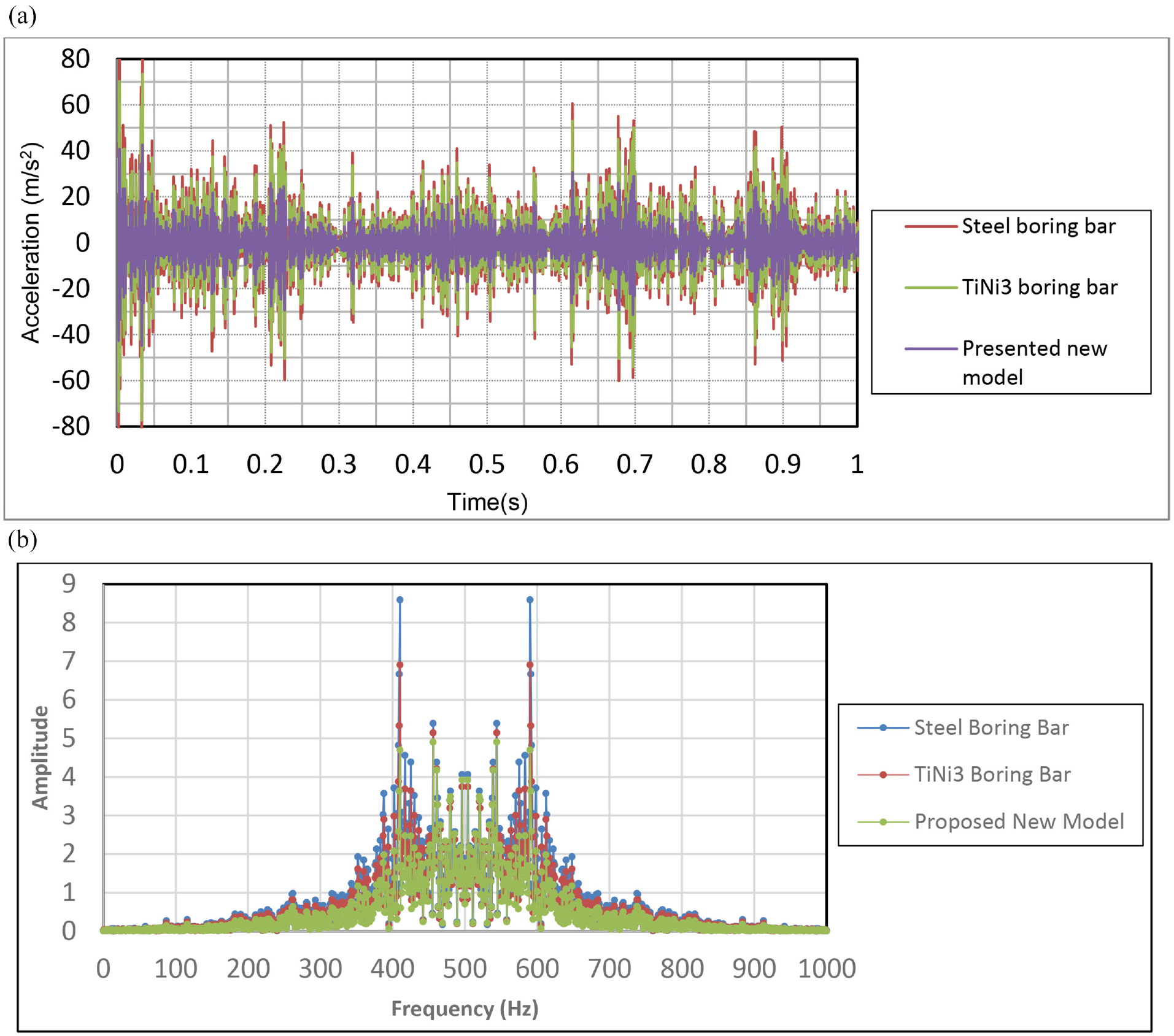
Figure 14 shows the vibration comparison between the commercial steel boring bar and the presented optimized new model. The latest design reached in the last optimization step shows an additional improvement in the boring bar’s performance. The vibration acceleration decreased by about 60.4% compared to the steel boring bar.
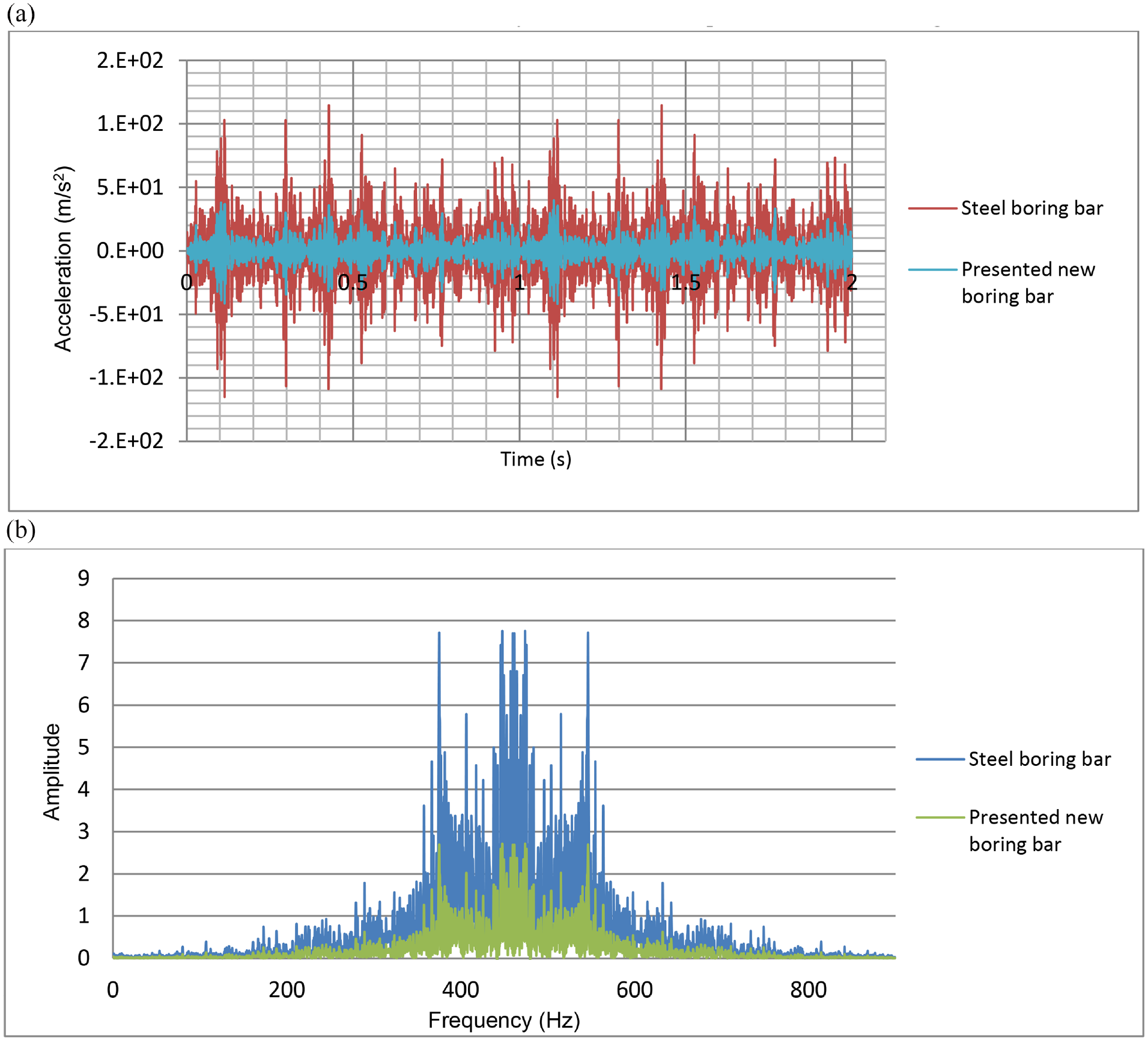
Comparison between commercial steel boring bar and presented optimized boring bar.
Conclusion
This paper has investigated the use of SMA to reduce vibration in the cutting tool during turning operations. This is considered a novel use of SMA materials since these alloys were almost exclusively used in civil engineering and medical applications. This work began by running numerical and analytical studies of the internal and external turning cutting tools. The analytical study was performed using the displacement function derived as a function of time and the longitudinal direction of the beam. The natural frequencies and mode shapes of the internal and external turning cutting tools were also found in the case of free vibrations. Later in the paper, we generated the displacement-time and acceleration-time graphs and their amplitude-frequency spectrum graphs for forced vibrations. The numerical study of internal and external turning cutting tools was carried out using ANSYS software utilizing modal analysis of free vibration and transient analysis of forced vibration. The cutting force from real experiment results was applied in analytical and numerical studies to obtain near realistic results. The presented finite element models of different cutting tools are verified by comparing analytical and numerical results showing good alignment.
The numerical results show that using TiNi3 alloy as cutting tool material, and the vibration acceleration amplitude has decreased by 40.2% for the prismatic cutting tool and 43.1% for the cylindrical one.
This paper has also presented a new boring bar model of TiNi3 alloy with carbide and foamed aluminum cores embedded inside and surrounded with four carbide plates. In addition, an optimization procedure of five steps was performed to obtain the optimal design and dimensions of the cores and plates. A numerical analysis of the optimized new model was performed to confirm the optimization results. Lastly, we verified the effectiveness of the presented new boring bar model by comparing the vibrations of the new boring bar and the commercial steel one. The results show that the vibration acceleration of the new model was decreased by about 60.4% compared to the commercial steel boring bar.
Footnotes
Appendix
Declaration of conflicting interests
The author(s) declared no potential conflicts of interest with respect to the research, authorship, and/or publication of this article.
Funding
The author(s) disclosed receipt of the following financial support for the research, authorship, and/or publication of this article: This work was supported by Scientific Research Projects Coordination Unit of Kırıkkale University. Project number 2019/177.