
Abstract
The vibration absorber has been effective in vibration control. From the demand of manufacturing structural parts with a deep hole, the design of a turning cutting tool with large length–diameter ratio is presented. An analytical approach of acquiring frequency response of primary structure equipped with typical single-degree-of-freedom vibration absorbers is formulated, and background modes are incorporated with the purpose of achieving an accurate tuning of vibration absorber. Specifically, the three-element type is investigated as the damping element of the vibration absorber embedded in the cutting tool contributes to the stiffness, although it demonstrates medium performance of vibration suppression according to non-dimensional analysis. The experimentally tuned frequency response function of the turning cutting tool with three-element vibration absorber achieves 87.1% reduction on the amplitude of the target mode. Finally, several configurations of internal turning operations are carried out to validate the design of the vibration absorber.
Introduction
Turning cutting tool with a large length–diameter ratio has been applied to manufacture structural parts with a deep hole. However, chatter vibration is apt to occur due to the flexibility of the cutting tool especially when the length–diameter ratio is larger than 4. Chatter vibration causes structural damage on machine tools and cutting tools and reduces machining accuracy and surface quality of the parts. The passive damper is an effective approach for vibration suppression, and its introduction into the turning cutting tool is beneficial to machining stability.
Investigations of the passive damper in the design of cutting tools have been reported. Edhi and Hoshi 1 designed a damped boring bar with a built-in friction damper to suppress high frequency chatter vibration above 5000 Hz. Ziegert et al. 2 investigated a damped milling cutting tool based on the principle of Kulun friction, and the critical stability depth was raised by 53%. Liu et al. 3 applied constrained layer damping structure in the milling tool holder to improve chatter stability. However, the vibration energy dissipated is dependent on the spindle speed. Biju and Shunmugam 4 proposed a boring bar for chatter suppression based on the particle damping principle, and the damping effect was optimal when the particle diameter is 3.17 mm and the filling ratio is 50%. Li et al. 5 proposed an optimal design of a vibro-impact nonlinear energy sink for vibration control and applied it to control the chatter of a cutting tool during a turning process. Nevertheless, the applicability of particle damper is restricted as its vibration reduction is quite affected by particle geometries when external vibration changes.
Above works are focused on vibration resistance by improving the damping ratio. However, the dynamic vibration absorber (VA) differs in that it increases both the damping ratio and stiffness by attaching a substructure to the primary structure. Moradi et al. 6 studied the position and stiffness of VAs under various milling conditions to minimize the vibration of cutting tool. Asgari et al. 7 designed an incremental sheet metal hammering system using mass VA for vibration reduction. Yang et al. 8 designed a milling cutting tool with large length–diameter ratio by embedding VA into the cutting tool bar, and the frequency response of the cutting tool in all directions can be reduced by 75%. Wang 9 designed a nonlinear VA equipped with additional series friction-spring element and demonstrated that critical cutting depth can be largely improved against the linear VA. Paul et al. 10 investigated the particle and mass impact VAs on tool vibration and cutting performance during turning. Shui and Wang 11 developed a VA with tunable piecewise-linear stiffness to enlarge the bandwidth of vibration absorption. Due to the simplicity and high efficiency, the VA is widely used in the design of damped cutting tools.
The earliest single-degree-of-freedom (SDOF) VA was proposed by Frahm. It was a simple structure with mass and spring and could only suppress vibration at frequencies close to the target mode. 12 On this basis, Ormondroyd and Den Hartog 13 developed classical Voigt VA by introducing damping and expanded the band of vibration suppression. Afterward, different types of VA are proposed. Ren 14 proposed a VA with damping element connected to the ground and showed that larger damping was achieved than Voigt VA. Asami and Nishihara 15 presented a three-element VA as the damping element made of viscoelastic material and blocks has a certain elasticity.
Researchers have made continuous effort on the optimization of design parameters since the emergence of various VAs. Ioi and Ikeda 16 obtained empirical formula of optimal parameters for Voigt VA. Keshtegar and Etedali 17 proposed an adaptive dynamic harmony search algorithm to optimize Voigt VA under white-noise base acceleration. Sims 18 proposed an analytical method to enhance chatter stability by shrinking the real part of the frequency response function, rather than its magnitude. Liu and Liu 19 utilized a perturbation method to obtain optimal design of grounded VA. Anh et al. 20 obtained approximated analytical solution of optimal parameters of three-element VA by equivalent linearization method. However, simplification of the primary structure as SDOF system in above works could be a lack of accuracy, as multi-DOF system is quite common in practice, and background modes are neglected.
In this study, an accurate and practical design methodology of VA is presented and applied to the turning cutting tool. The VA is established as three-element type considering the stiffness of the damping element, and the response incorporating background modes is formulated analytically. In section “Materials and methods,” the design of the damped cutting tool is presented, while the dynamics of the turning cutting tool equipped with typical types of SDOF VAs (i.e. Voigt VA, three-element VA, and grounded VA) are formulated. In section “Results and discussion,” the above-mentioned SDOF VAs are compared numerically based on H∞ criterion, and advantages of the proposed methodology are verified. Finally, the application to the cutting tool with VA is validated by carrying out several configurations of internal turning operations. The article is concluded in the end.
Materials and methods
Design of the turning cutting tool
A turning cutting tool with length–diameter ratio of 7 and external diameter of 25 mm is designed with three sections, that is, tool head, tool holder, and tool bar (Figure 1). The tool head is connected to the tool holder by fastening screws, and the tool holder is connected to the tool bar by threads. The VA cantilevered at the end of tool holder is placed inside the tool bar.
Structural design of the turning cutting tool.
The tool bar and tool holder are made of tool steel H15. It is a low-carbon steel with carbon content of 0.17%–0.24%. Its yield strength and tensile strength are 939 and 1018 MPa, respectively. It is widely used to manufacture cutting tool due to its high strength, and excellent machinability and fatigue resistance. The tool head is Sandvik 570-SCLCL-25-09 and the blade is Sandvik CCMT09T304-PF4325 with a coating of chemical vapor deposition (CVD) Ti(C, N) + Al2O3 + TiN and a rear angle of 7°. The blade thickness is 3.969 mm.
The structural components of the embedded VA are shown in Figure 2. The mass block is made of high-density tungsten for achieving optimum vibration suppression within limited space and located at the end of the spring rod made of spring steel. The rubber gasket made of polyurethane is fixed on the spring rod by utilizing an interference fit and fill in the cavity of the tool bar. The other end of the spring rod is threaded to the tool holder. The axial position of the mass block on the spring rod can be tuned by the flat head screw connection; therefore, frequency tuning of the VA can be achieved over a wide range by adjusting the effective overhang of the spring rod. Damping is generated by the rubber gaskets and can be tuned by its material model, quantity, and preload.
Structural design of the VA.
Dynamics formulation
The dynamic model of the turning cutting tool with SDOF VA is shown in Figure 3. The cutting tool m0 is assumed with a harmonic excitation F due to the intersection of rotating workpiece and stationary cutting tool during the turning process. The equation of motion of the overall system can be expressed as equation (1)
where m0, k0, and c0 are the mass, stiffness, and damping of the turning cutting tool, respectively; m1 and k* are the mass and complex stiffness of SDOF VA; x0 and x1 are the displacements of the cutting tool and SDOF VA.
The dynamic model of the turning cutting tool embedded with SDOF VA.
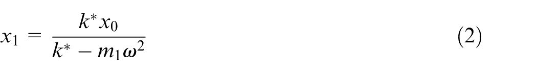
By solving equation (1), x1 can be obtained as
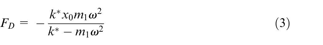
As the force FD applied to the turning cutting tool from the SDOF VA is k*(x0–x1), it is given by
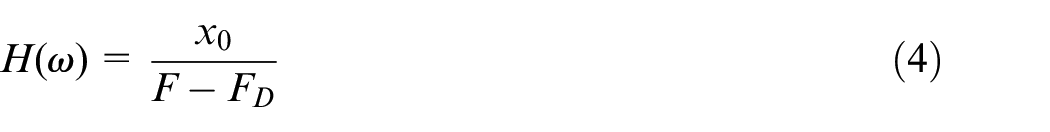
Considering VA as an external force applied at the connection point, the frequency response function (FRF) of the turning cutting tool can be expressed as
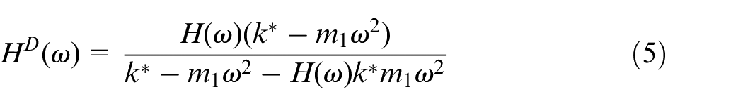
Substituting equation (3) into equation (4), the FRF of the turning cutting tool with SDOF VA is obtained 21
The k* for the SDOF VAs described in Figure 4 is presented below. A detailed formulation can be referenced with Appendix 2.
For Voigt VA

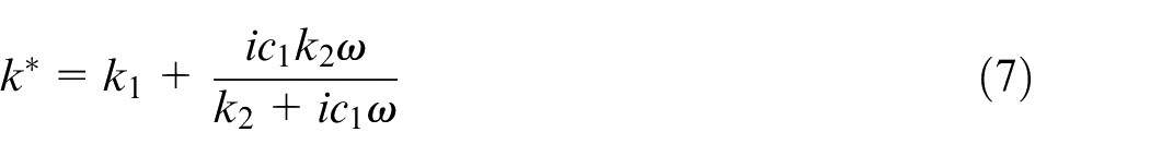
For three-element VA
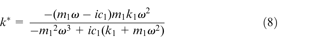
For grounded VA
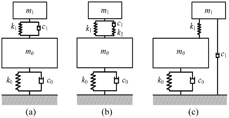
Typical types of SDOF VAs: (a) Voigt VA, (b) three-element VA, and (c) grounded VA.
The design parameters of the VAs are varied depending on its type (Figure 4). According to the above formulation, the design parameters are m1, k1, and c1 for Voigt and grounded VAs, and m1, k1, k2, and c1 for three-element VA. Since the mass of VA is predetermined due to limited working space, the left design parameters are k1 and c1 for the Voigt and grounded VAs, and k1, k2, and c1 for three-element VA. Optimum design parameters of the VA are obtained by carrying out the following numerical optimization.
Results and discussion
Comparison of VAs based on non-dimensional analysis
The non-dimensional analysis is performed to compare the damping performance of the three types of SDOF VAs. After introducing the non-dimensional terms (Table 1), the non-dimensional FRF HN(β) for each VA in Figure 4 is formulated as equations (9)–(11) and details are presented in Appendix 3.
For Voigt VA

For three-element VA

For grounded VA

Non-dimensional parameters.
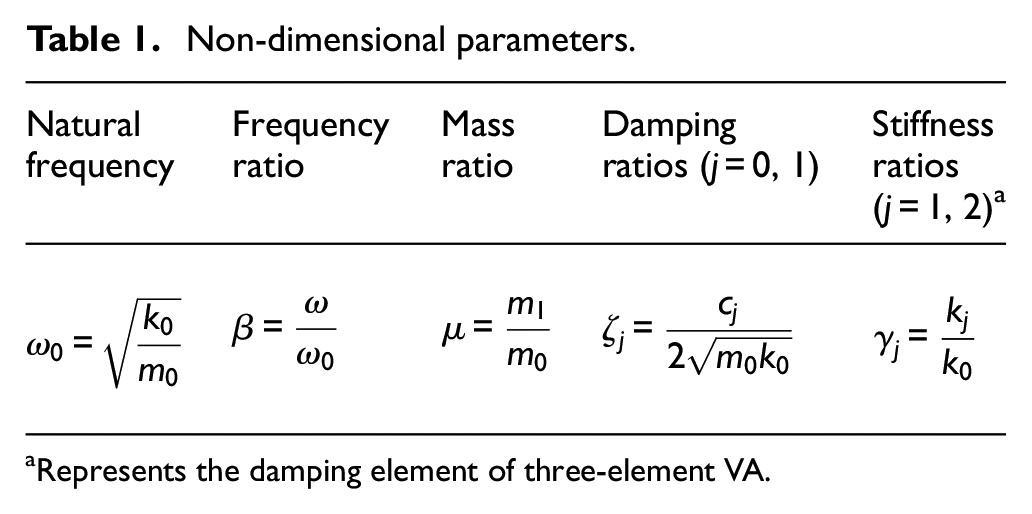
Represents the damping element of three-element VA.
By following H∞ criterion of achieving minimum vibration amplitude, the optimization algorithm is implemented in MATLAB using the fminimax function. The design parameters k1, k2, and c1 of VA are optimized numerically for a specified μ. Compared to the Voigt VA, the three-element and grounded VAs reduce further the maximum amplitude of HN(β) by 5.7% and 12.8%, respectively, for μ = 10% and ζ0 = 1% (Figure 5).
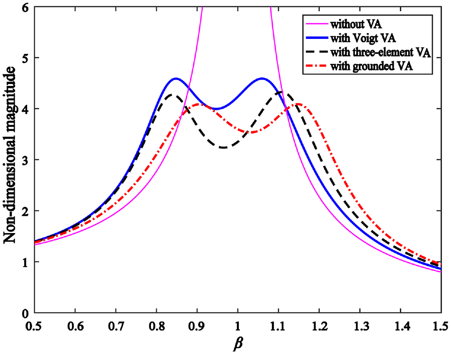
Non-dimensional FRF of different VAs for μ = 10% and ζ0 = 1%.
By varying the mass ratio μ and damping ratio ζ0, the maximum amplitude of optimized HN(β) for all the three VAs decreases as μ or ζ0 increases, and HN(β) are more sensitive to ζ0 than μ (Figure 6(a) and (b)). There is a minor change on the maximum of HN(β) when μ is greater than 6%, while the decrease is remarkable when ζ0 increases from 1% to 10%. In addition, it is evidenced that the grounded VA achieves the best vibration suppression. It is explained that stable damping can be maintained despite of the external vibration, as its damping element is disconnected with the primary structure. The three-element VA achieves better vibration suppression than Voigt VA, as an additional stiffness variable generated by the elasticity of the damping element is introduced. As it would be unpractical to apply grounded VA to the turning cutting tool, three-element VA is employed in this study as its dynamic model can better reflect the actual characteristics of the VA embedded in the cutting tool.
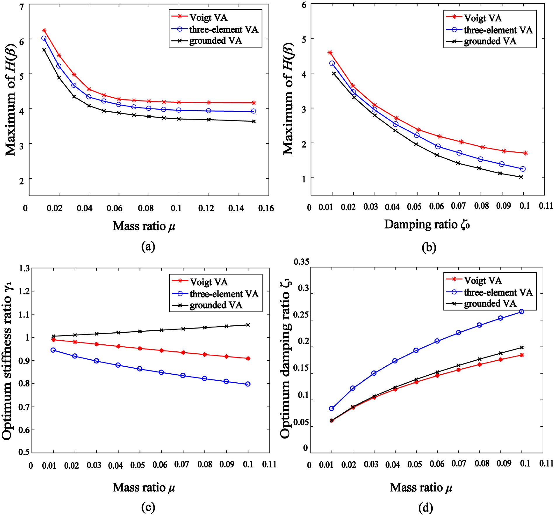
Numerical analysis of Vogit, three-element, and grounded VAs: (a) ζ0 = 1%, (b) μ = 5%, (c) ζ0 = 1%, and (d) ζ0 = 1%.
Furthermore, the optimum stiffness ratio γ1 and damping ratio ζ1 with different mass ratio μ are presented. It is seen that the optimum stiffness ratio γ1 of Voigt VA and three-element VA is always larger than unity, while it is less than unity for grounded VA (Figure 6(c)). The optimum damping ratio ζ1 of all the three VAs increases with μ, while the three-element VA requires the largest damping (Figure 6(d)).
Frequency response function
The advantages of the three-element VA are further verified (Figure 7(a)) by utilizing a practical case. Hammer test is carried out to acquire the FRF H(ω) of the turning cutting tool without VA. The excitation is inputted by a hammer with a sensitivity of 2.25 mV/N, and the acceleration is collected by an accelerometer 8778A500 with a sensitivity of 9.74 mV/g. The signals are fed to the data acquisition card NI 9234 and processed by the software CutPro V9.3. Afterward, the mass ratio μ is identified as 17%, and Voigt and three-element VAs are optimized based on equations (5) and (6) and equations (5) and (7), respectively. The amplitude of the optimum FRF after damping with three-element VA is 2.98e–6 m/N, while it is 3.52e–6 m/N with Voigt VA, corresponding to 15.3% reduction.
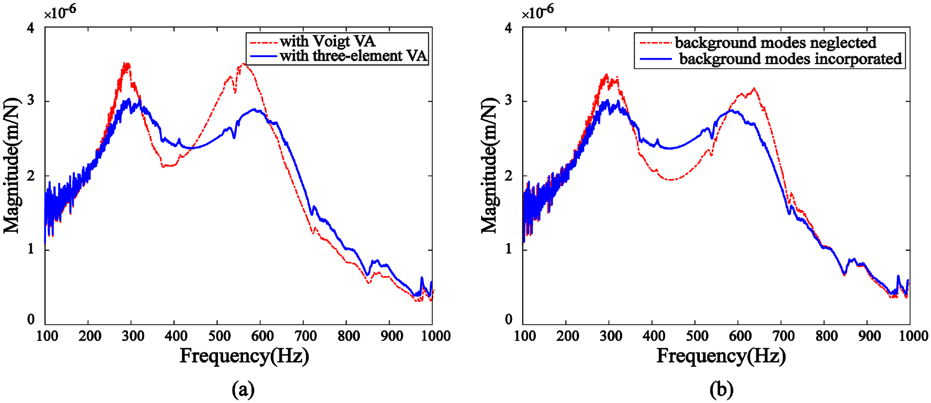
Optimal FRF of the turning cutting tool with VA through simulation: (a) comparison of Voigt and three-element VAs and (b) comparison of three-element VA without and with background modes.
Furthermore, the effect of background modes from the primary structure is analyzed. By identifying the dynamic parameters of the target mode at 525 Hz, the three-element VA is optimized without considering background modes based on equation (10). The corresponding optimum FRF of the cutting tool with VA is shown in Figure 7(b). Alternatively, the three-element VA is optimized based on equations (5) and (7) which utilizes the FRF directly and incorporates the background modes. Compared to the optimization without considering background modes, the magnitude is reduced by 9.1% and the peaks of split modes at 430 and 591 Hz are distributed equally. The cutting tool can be treated as a cantilever beam and contains multiple modes, and its simplification to SDOF system causes deviations on the optimum design parameters of the VA. For comparison, the optimum design parameters of three-element VA without and with considering background modes are shown in Table 2.
Optimal design parameters of three-element type VA.
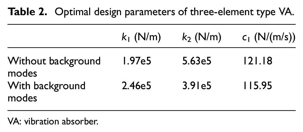
VA: vibration absorber.
By following the optimum design parameters in Table 2, the three-element VA is tuned and experimental FRF of the cutting tool with VA is obtained (Figure 8). The maximum reduction of the magnitude of the FRF is 87.1% when mass ratio μ = 17%. For comparison, the experimental results in the literatures are presented. A reduction of 49% is observed in Lee et al. 22 by designing a dynamic VA with μ = 25%, and a reduction of 36% by particle VA and 62% by mass impact VA with μ = 10% is achieved in Paul et al. 10 However, the amplitude of the experiment is 76% higher compared to the optimum FRF through simulation, due to the error from the VA tuning and cutting tool clamping.
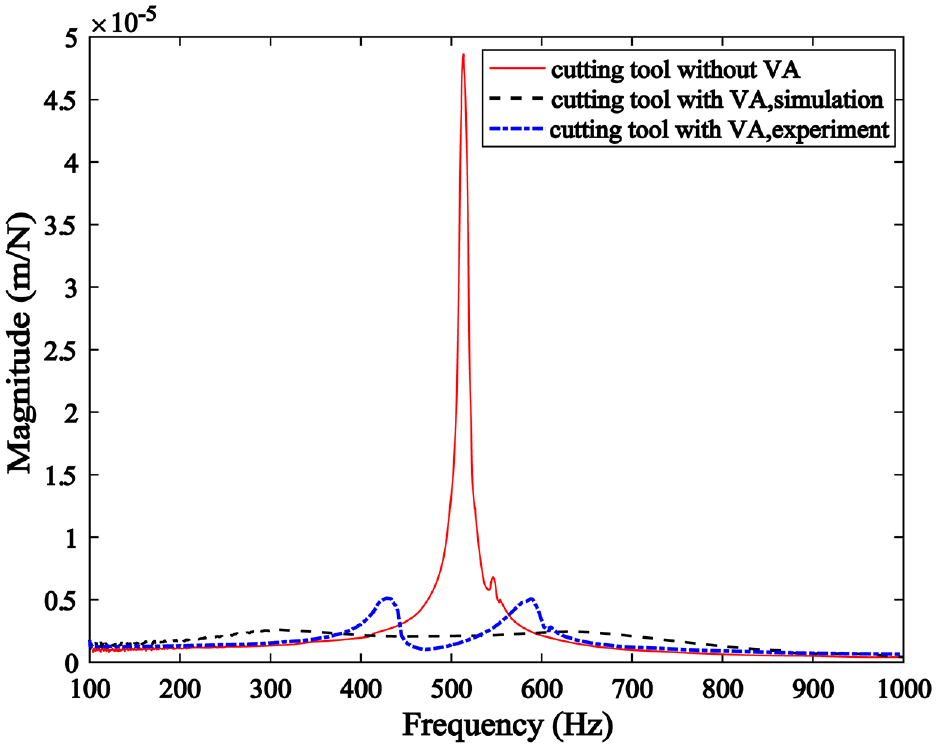
Optimal FRF of the turning cutting tool equipped with three-element VA.
Machining tests
To verify the damping performance of the designed turning cutting tool, internal turning operations are implemented on Lathe HTC2050 (Figure 9). According to the specification, the spindle speed ranges from 50 to 4000 r/min and maximum output torque is 88 N m. The workpiece is aluminum alloy 7075 with hardness of 160 HB. Its yield strength and tensile strength are 503 and 572 MPa, respectively, and melting point ranges from 475 °C to 635 °C. The cylindrical workpiece is 68 mm in length, 76 mm in outer diameter, and 43 mm in inner diameter. Microphone GRAS 40PH with a sensitivity of 45.86 mV/Pa is used to evaluate the audio signals. Several configurations of internal turning operation with different cutting depth ap are performed with n = 300, 400 and 500 r/min, and f = 0.05 r/min.
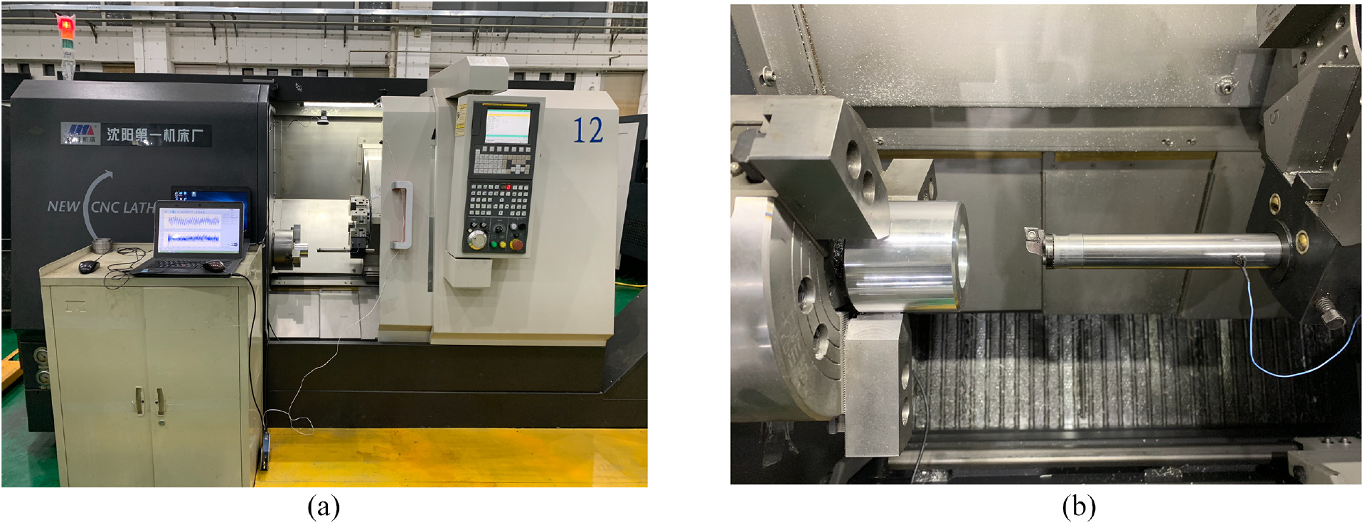
Experimental setup: (a) machine tool and (b) turning cutting tool with VA.
Case 1: ap = 0.2 mm and f = 0.05 mm
The machining signals of turning process without and with VA are shown in Figures 10 and 11. The maximum sound and acceleration of the turning process without VA is 1 Pa and 15 mm/s2 when axial depth of cut ap = 0.2 mm, feed rate per revolution f = 0.05 mm and workpiece rotation speed n = 300 r/min (Figure 10(a)), and it is reduced to 0.5 Pa and 4 mm/s2 after using the cutting tool with VA (Figure 11(a)). After performing Fourier transformation, the turning process without VA is dominated by the frequency harmonic of 575 Hz and is identified as chatter (Figure 10(a)). However, the frequency harmonics of the turning process with VA are distributed at 470, 525, and 590 Hz (Figure 11(a)). Meanwhile, the machined surface profile is measured by the surface roughness meter Links 2205. For a sampling length of 0.8 mm, the Ra is reduced from 1.41 μm (Figure 10(a)) to 0.64 μm (Figure 11(a)) after damping.
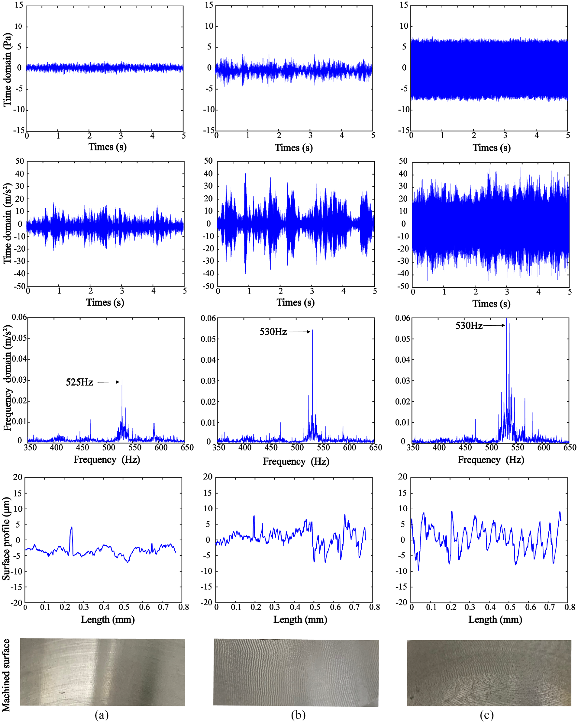
Machining process without VA for ap = 0.2 mm and f = 0.05 mm/r: (a) n = 300 r/min, (b) n = 400 r/min, and (c) n = 500 r/min.
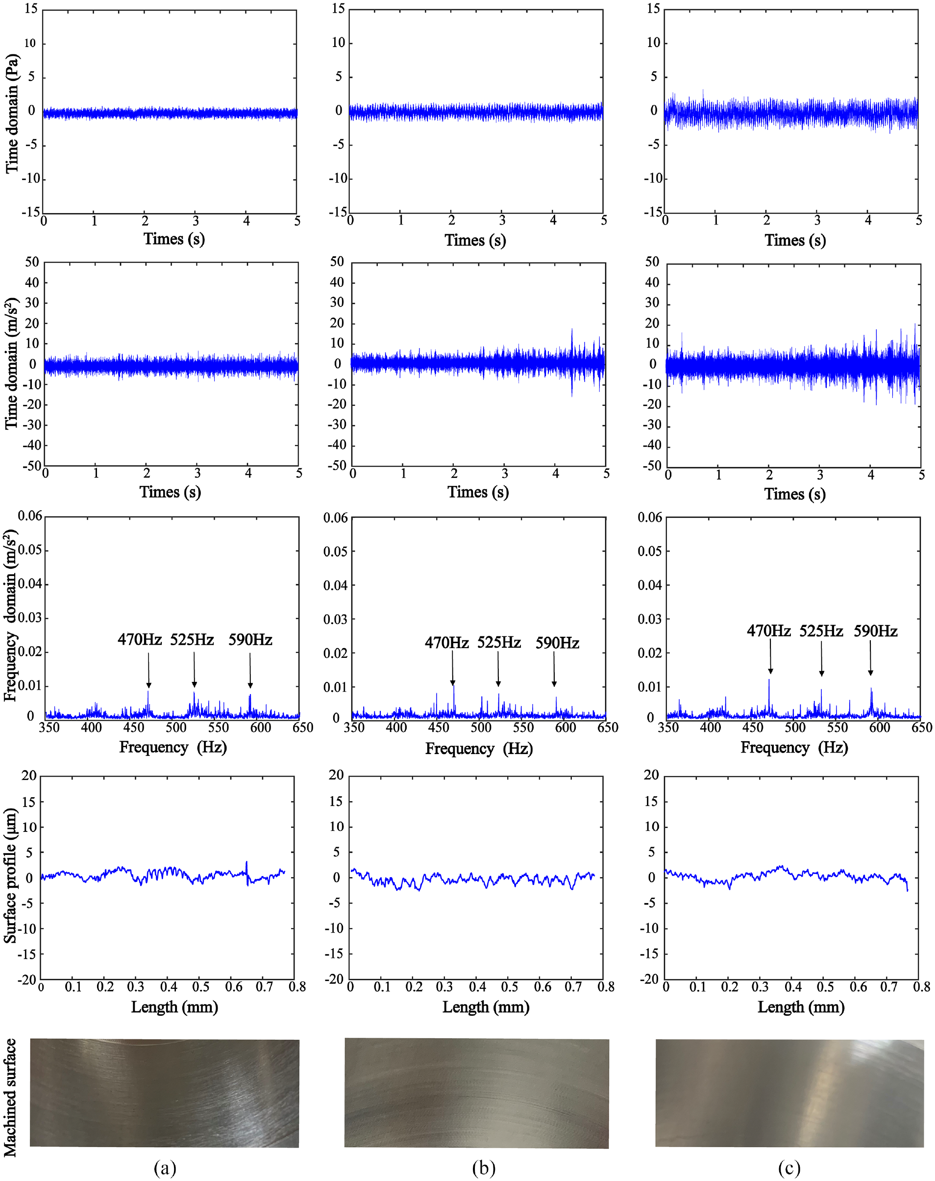
Machining process with VA for ap = 0.2 mm and f = 0.05 mm/r: (a) n = 300 r/min, (b) n = 400 r/min, and (c) n = 500 r/min.
Next, n is increased to 400 and 500 r/min while ap and f are kept unchanged. The maximum sound amplitude of the turning process without VA is 4 and 7 Pa, respectively (Figure 10(b) and (c)), and it drops to 1.5 and 2.5 Pa after damping (Figure 11(b) and (c)). Meanwhile, the accelerations are more fluctuating than n = 300 r/min. The maximum acceleration of the cutting tool without VA is 20 and 40 mm/s2, respectively (Figure 10(b) and (c)), and are reduced to 10 and 15 mm/s2 for the cutting tool with VA (Figure 11(b) and (c)). Additionally, the decrease of the surface profile Ra confirms the improvement of cutting stability. As an example of n = 500 r/min, the reduction on the sound, acceleration and workpiece surface profile is 64%, 63%, and 68%.
Case 2: ap = 0.4 mm and f = 0.05 mm
Machining tests are conducted for ap = 0.4 mm and f = 0.05 mm while the workpiece rotation speed n ranged from 300 to 800 r/min (Figure 12). It is demonstrated that the machining stability is much improved after employing the designed cutting tool with VA. The machining sound, acceleration and machined surface profile are reduced by 67%, 87%, and 73% when n = 400 r/min, and are reduced by 60%, 73%, and 72% when n = 600 r/min.
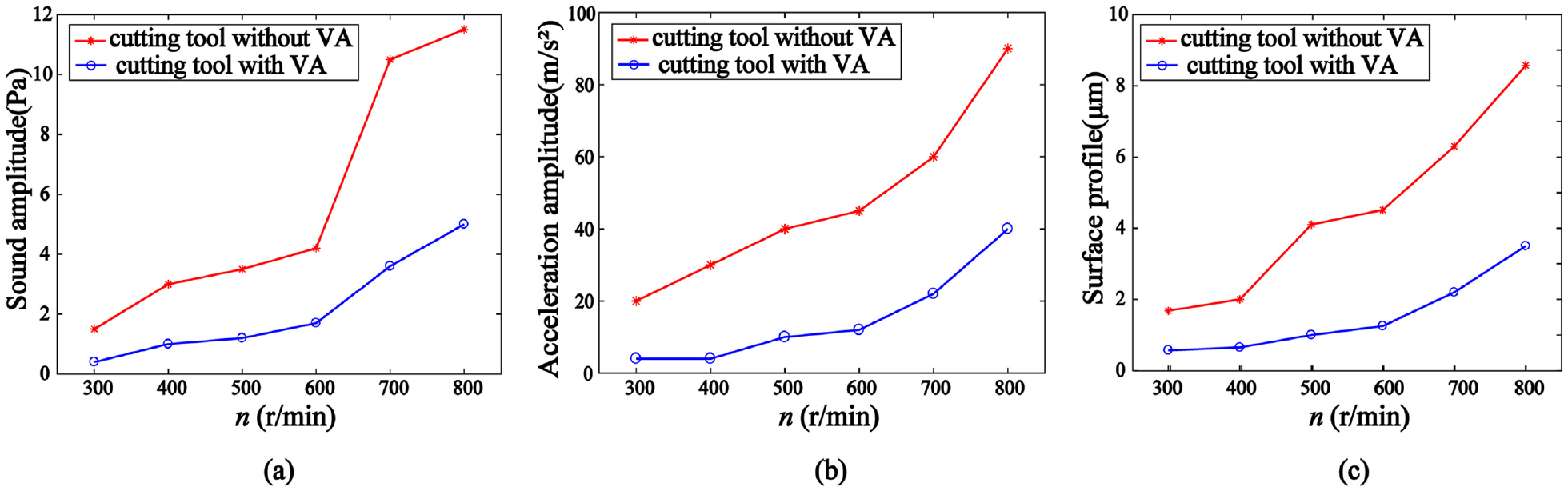
Machining signals at different n while ap = 0.4 mm and f = 0.05 mm/r: (a) machining sound, (b) acceleration, and (c) machined surface profile.
For the designed cutting tool with VA, the sound, acceleration, and surface roughness increase significantly when n is larger than 600 r/min. Therefore, the optimum workpiece rotation speed n for the designed cutting tool is 600 r/min when ap = 0.4 mm. Besides, the cutting tool with VA achieves better vibration suppression with a larger ap. For the case when n = 500 r/min, the machining sound, acceleration, and machined surface profile are reduced by 64%, 63%, and 68% for ap = 0.2 mm, and reduced by 69%, 75%, and 76% for ap = 0.4 mm.
Conclusion
A design methodology of VA is presented and applied to turning cutting tool with large length–diameter ratio. An analytical approach of acquiring frequency response of primary structure equipped with typical SDOF VAs (i.e. Voigt, three-element, grounded) is formulated by utilizing the experimental FRF. Therefore, background modes of primary structure are incorporated during the optimization design of VA, in contrast to the modes neglect especially when simplifying the multi-DOFs primary structure.
The three-element VA is employed in the design of turning cutting tool as damping element of the embedded VA contributes to the stiffness, although it demonstrates medium vibration suppression performance among the three typical SDOF VAs according to non-dimensional analysis. Taking a practical example of the turning cutting tool, the three-element VA has a further reduction of 15.3% on the FRF magnitude than the Voigt VA, and optimization by incorporating background modes achieves 9.1% reduction than the case of neglect.
The design routine of the VA is validated by the experimental tuning of the FRF and machining tests. It is evidenced that the FRF amplitude of the target mode is reduced by 87.1% after experimental tuning. Several configurations of internal turning operations are implemented. For the case when n = 500 r/min and f = 0.05 mm, the machining sound, acceleration, and machined surface profile are reduced by 64%, 63%, and 68% for ap = 0.2 mm, and reduced by 69%, 75%, and 76% for ap = 0.4 mm.
Footnotes
Appendix 1
Appendix 2
Appendix 3
Declaration of conflicting interests
The author(s) declared no potential conflicts of interest with respect to the research, authorship, and/or publication of this article.
Funding
The author(s) disclosed receipt of the following financial support for the research, authorship, and/or publication of this article: This work was supported by the National Natural Science Foundation of China (Grant nos 51675032 and 91960108) and Fundamental Research Funds for the Central Universities (Grant no. YWF-19-BJ-J-72).