
Abstract
Hydro-mechanical deep drawing (HMDD) process is comparatively a new technique in sheet metal forming. The present study focuses on the use of HMDD for bimetallic components comprising aluminum and steel sheets as well as aluminum and magnesium blanks. Carrying out both experiments and numerical simulations, the effects of process parameters such as drawing depth, the fluid pressure inside the die and the process temperature were profoundly investigated. To study the effect of the process temperature on the quality of the product, the specimens were formed at both the room temperature and 200°C. Considering the maximum thickness strain and thickness variation of the specimens as measures of product quality, various results, including those obtained from the design of experiments (DOE), illustrated significant impacts of all the considered factors on the quality of the final product. The findings also showed that for the bimetallic aluminum/steel specimen, the Al/St layer sequence offered a higher quality compared with the St/Al arrangement under the same process conditions. The amount of thickness strain and thickness variation in the Al/St arrangement, compared with the St/Al sequence, were respectively improved by 27.4% and 12.6%, for the optimal value of the maximum fluid pressure (150 bar). Moreover, the thickness variation of the Al/Mg specimen was smaller than that of Al/St bimetallic cup, regardless of the drawing depth.
Keywords
Introduction
Metal forming processes are among the most commonly applied production methods in many industries due to the excellent mechanical properties of their final products and extended applications in various manufacturing industries. 1 Sheet metal forming processes (like deep drawing operation) is one of the most remarkable types of metal forming operations and plays a significant role in various industries. 2 Hydro-mechanical deep drawing (HMDD) process is one of the newest methods in sheet metal forming. 3 This method employs fluid pressure in addition to mechanical force to deform a sheet. In a HMDD operation, the radial pressure exerted on the edge of the part by the surrounding medium facilitates the flow of the sheet into the die cavity, thus improving the drawing ratio and reducing the forming load. 4 In comparison with the conventional deep drawing process, HMDD offers advantages such as the capability of producing intricate shapes, higher dimensional accuracy due to the limited spring-back, excellent thickness uniformity across the part, higher drawing depth, a better distribution of strain, and lower costs. 5 Despite these advantages and the broad applicability of the HMDD, using a fluid as the forming medium has complicated the process and a larger number of parameters could affect the formability of the sheet. An imprecise adjustment of these variables could result in wrinkling or tearing of the sheet. Therefore, to achieve high-quality parts, an accurate study of the effect of each variable on the sheet formability is necessary. Modanloo et al. 6 performed a comprehensive analysis of the thinning of the workpiece in the hydrodynamic deep drawing process. In their study, optimization was carried out based on Taguchi method. The results demonstrated an improvement in thinning parameter (about 11%) in comparison with the conventional operation.
Composite materials have found several applications in electronic, automotive, and aerospace industries. Each layer of the composite may provide different mechanical, physical, or chemical properties. As a result, the favorable properties including high yield stress, resistance to rupture, and electrical conductivity that a metal may lack can be achieved by combination with other materials.7,8 Several researches have addressed the forming of single metallic, bimetallic, and multi-metallic. Fazlollahi et al. 9 studied hydro-mechanical deep drawing process of sandwich sheets. The goal of their research was to achieve higher drawing ratios. In another study, Liu et al. 10 studied the effects of properties of multi-layer composites on the forming limits in hydroforming process. In their research, a comparison was made between the formability of two composite materials consisting of three-layered aluminum and aluminum-composite laminates subjected to a uniform blank holder force. Yaghoubi and Fereshteh-Saniee 11 investigated the hydro-mechanical deep drawing operation to produce bimetallic spherical-conical cups. In their research work, the influence of fluid pressure on uniformity of the final product studied experimentally, numerically, and analytically.
One of the most important issues in metal forming processes is to improve the uniformity of the products and avoid a number of defects such as tearing and wrinkling. 12 Several factors, such as the process parameters and the die geometry, affect the formability and thickness distribution of final product obtained from the forming process. 13 On the other hand, regarding composite materials, earlier studies often focused on the maximum thickness reduction and thickness distribution of the entire bimetallic specimen. However, given the significance of the thickness distribution and the uniformity of each layer, the thickness variation was also taken into account in this investigation for both the sheets and the bimetallic composite in addition to the maximum thickness reduction. The effects of the main process variables, namely the drawing depth (DD), the fluid pressure inside the die container and the process temperature, on the maximum thickness strain and the thickness variation were examined for different layer sequences. The 1200 Al alloy, St13 steel and AZ31B magnesium alloy were employed in this research. In order to study the influence of process temperature on the HMDD process, a comparison was also made between the bimetallic aluminum/steel (Al/St) and aluminum/magnesium (Al/Mg) samples.
Experimental procedure
As it was mentioned earlier, 1200 aluminum alloy, St13 steel, and AZ31B magnesium alloy were used in this study. The corresponding engineering stress–strain curves obtained from uniaxial tensile tests conducted on a STM-50 universal testing machine and the relevant mechanical properties and chemical compositions of the employed materials are shown in Figure 1. The bimetallic cups were produced using the HMDD set up illustrated in Figure 2. The die set is divided into the mechanical and hydraulic components. The mechanical parts of the die include the matrix, the blank holder and the punch. The blank holder was screwed to the matrix and remained fixed throughout the process. The hydraulic parts of the system involve the manual pump, the safety valve, the relief valve, and the pressure gage. This circuit acts in such a way that, by moving the punch into the die cavity, the fluid previously pumped into that die is compressed. In order to adjust the maximum pressure gained in the chamber, a safety valve is used to relieve the excessive pressure. Heating elements were also placed underneath the die set in a symmetrical configuration to investigate the effect of process temperature on the uniformity of the formed products. Both the Al/Mg and Al/St specimens were deep-drawn at 200°C.
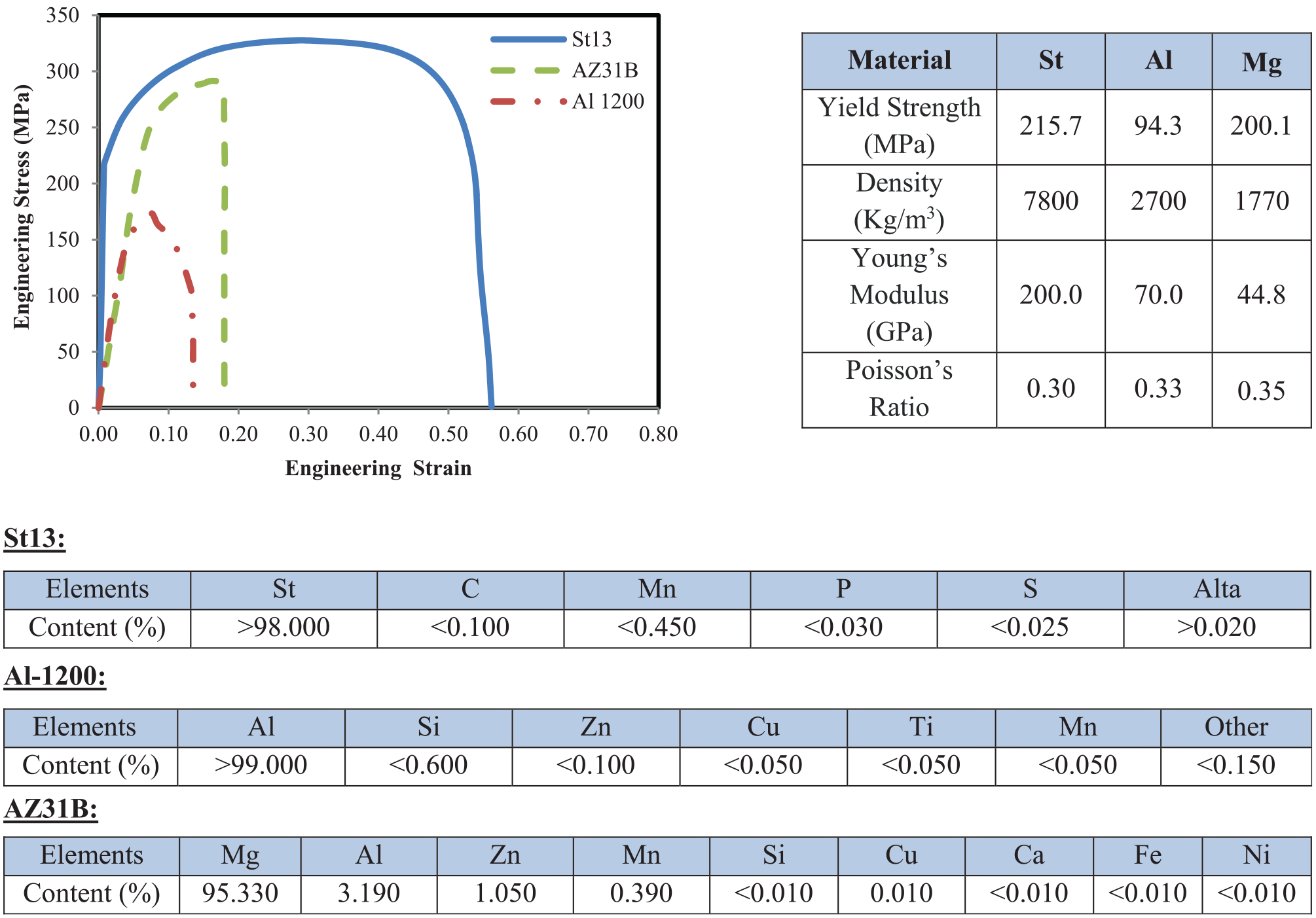
The engineering stress–strain curves and properties of the materials employed in the present research.
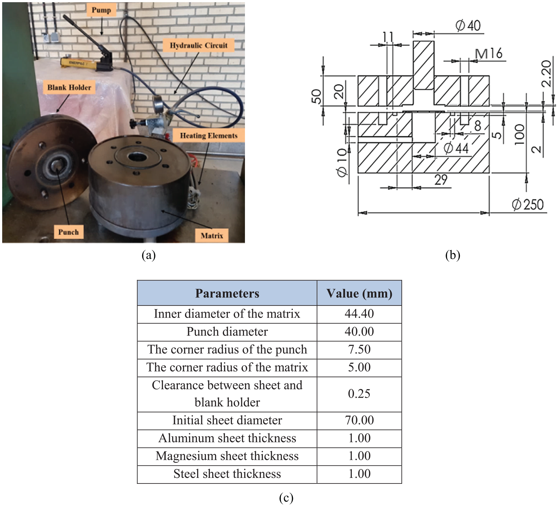
The die set designed for HMDD tests: (a) the hydraulic circuit and the unassembled mechanical components, (b) a cross-section of the die set, and (c) values of the geometrical parameters.
Finite-element simulations
To numerically simulate the HMDD process, Abaqus software was employed. In the present research, the total Lagrangian formulation based on an extension of a thin shell theory, in which large membrane and bending strains are taken into account, has been used for finite element simulation of the HMDD operation. By applying the virtual work principle and constitutive equations, linearized stiffness equations in the rate form can be derived following the standard procedure.14,15 Knowing the symmetry of the experimental assembly, to observe the possibility of wrinkling in the FE model and to reduce the computational time, a quarter of the worksheet and the die set were three-dimensionally created in the software. The workpiece was modeled as a deformable part, using reduced integration shell element (S4R). The punch, the blank holder and the matrix were selected to be as discrete rigid surfaces. The stress-strain diagrams shown in Figure 1 were converted into the true ones to perform the FE analyses. In the “interaction” module, the surface-to-surface (explicit) contact state and the Coulomb’s friction law were applied. The friction coefficient was considered to be 0.06 due to the presence of an oil layer at the contact surfaces of the sheet with the matrix and the blank holder. Moreover, the friction coefficient between the blank and the punch was defined to be 0.15. 16 Based on the observations made in the practical tests, there was a minor slip between the layers during the forming process. For this reason, the “no-slip” mode of the software was considered between the layers of the composite blank in the FE simulation. Figure 3(a) shows a bimetallic specimen after performing the relevant FE simulation. As an essential variable in sheet metal forming, the diagram of the minimum sheet thickness versus the number of elements in the radial direction was obtained (See Figure 3(b)). Based on this diagram, and to avoid a large CPU time and reduce the costs involved, the number of elements in the radial direction was selected to be 50. To gain graph shown in Figure 3(b), the fluid pressure, the drawing depth, and the layer sequence were considered to be 50 bar, 0.5, and St/Al, respectively.
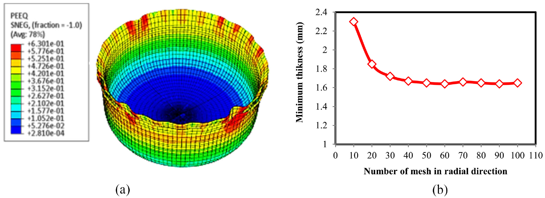
Numerical simulation of the HMDD process: (a) a view of the bimetallic specimen and (b) the mesh convergence study diagram.
Results and discussions
Several criteria are defined in sheet metal forming to succeed producing a perfect product. Previous researches mostly assumed the percentage maximum thickness reduction as an index for measuring the quality of the final cup. The thickness strain is the most important parameter in analyzing the quality of specimens fabricated via various sheet metal forming processes. Value of this parameter can be obtained through the following equation:
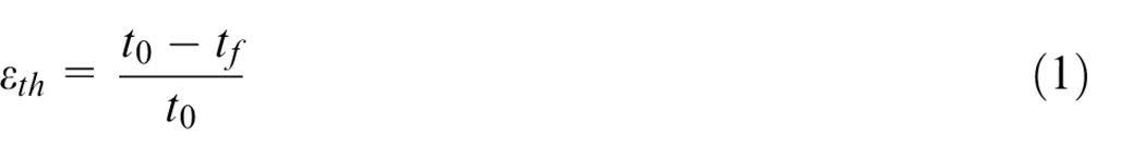
where t0 and tf are respectively the initial thickness of the sheet and the thickness of the each point of the produced cup at the end of the process, respectively. The final product of a forming process should possess excellent quality. Different criteria can be assumed as the measure for the final product quality, including uniformity and maximum thickness reduction. A higher uniformity of a cup indicates a minimum difference between the thickness at different sections of the final product and the average sheet thickness. In other words, the lower the difference between the final product thickness and the mean sheet thickness, the lower become the thickness variation and the greater is the uniformity of the cup. With this regard, equation (2) was used to calculate the thickness variation 3 :
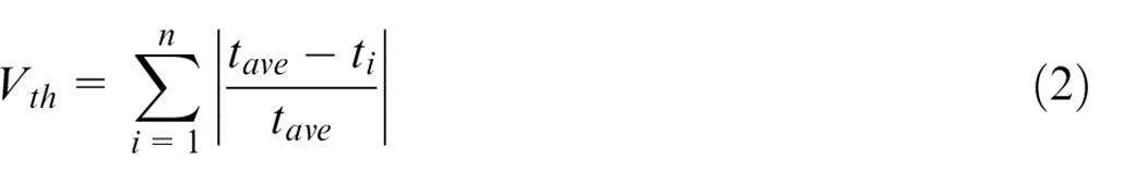
where n is the number of points selected on the profile of the deformed part for measuring the thickness, tave is the average thickness of the whole product, and ti is the sheet thickness at each specific point on the profile of the drawn cup. It should be noted that both the maximum thickness strain and the thickness variation are dimensionless parameters. As the height of the specimen increases, the plastic strain and thinning of the workpiece can change. The height-to-diameter ratio of the product is introduced as a dimensionless index of the drawing depth (DD):
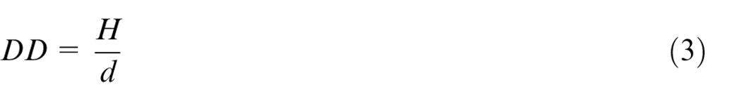
where H (mm) represents the depth of the final product and d (mm) stands for the cup diameter. To validate the simulation results, (εth)max obtained under different conditions was compared with experimental findings, as illustrated in Figure 4. Parameter (εth)max is the maximum thickness strain of the sheet, corresponding to the region of the workpiece possessing the minimum thickness. The maximum thinning of the deformed sheet usually occurs at the contact area with the punch tip. The agreement between the FE model and experimental results is encouragingly very good and the maximum difference between these findings is about 12%. The behavior of a laminated blank in a forming process is different from a single layer sheet and depends on the layer sequence. Because of distinct mechanical characteristics for each layer, changing the layer sequence leads to variations in fracture and uniformity of the final bimetal cups. The necking strain in aluminum sheet is less than the steel one. When the aluminum sheet is at the bottom of laminated composite workpiece, more tension occurs in it, and by performing the HMDD process, this layer is torn earlier. The friction in the punch-steel sheet interface, on the other hand, is higher than that between the punch and an aluminum layer. 17 Additionally, the lower ductility of the aluminum blank, in comparison with the steel sheet, has led to a greater thinning for St/Al stacking sequence compared with the Al/St one under all the test conditions. It should be noted that at a pressure of 250 bar, the bimetallic sample with St/Al sequence was torn. Investigating the influence of process variables on the quality of the final product is the aim of the present research. These variables have various effects on different regions of the deformed blank. For this reason, the product profile is divided into three major areas, namely the bottom or the base of the cup (A), the area which is in contact with the punch edge (B), and the main wall of the cup (C).
The measured maximum thickness strain for various HMDD tests in term of: (a) the maximum fluid pressure and (b) drawing depth (DD).
Design of experiment
The purpose of this section is to employ the design of experiments (DOE) technique to evaluate and quantify the influences of process variables on the quality of the final double-layer cup. Due to the importance of both the quality factors, that is, the maximum thickness strain and thickness variation, a combination of these two components was considered for evaluation of success of the HMDD operation (See equation (4)). Reducing both of these parameters increases the quality of the final component. For this reason, the aim of the experiments should be to reduce the amount of Y parameter defined as below:

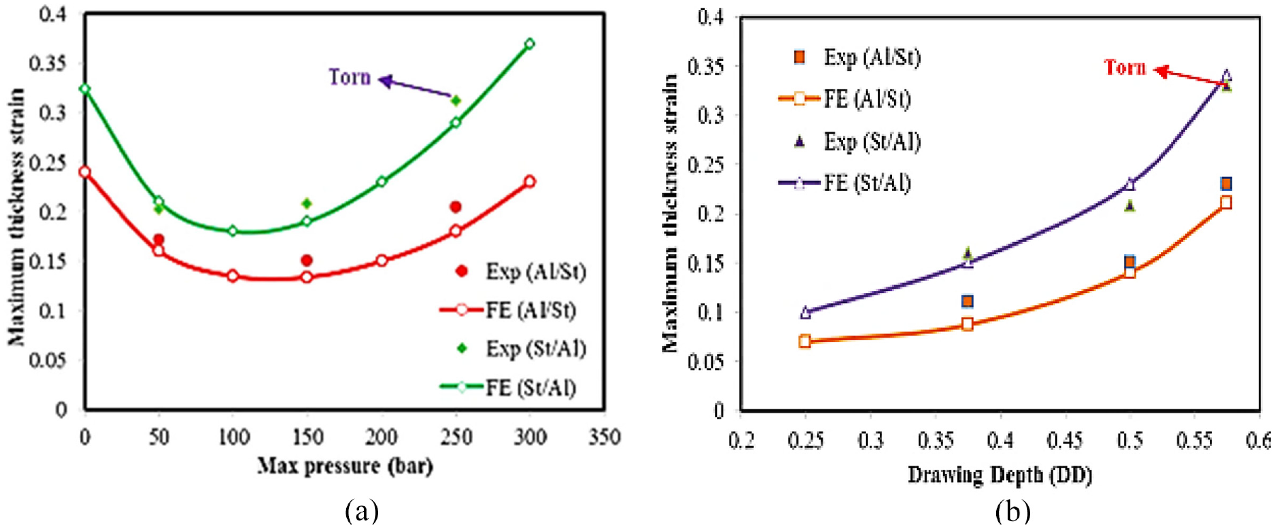
Figure 5 expresses the outcomes gained from the DOE analysis. As shown in the table of experimental conditions (Figure 5(a)), the process variables include the fluid pressure (at three levels), stacking sequence of the composite blank (having two levels) and the drawing depth of the specimens (at two levels). Accordingly, 12 practical experiments have been performed for a full factorial design. Based on Figure 5(b), the normality of the experimental results is clear. The findings presented in Figure 5(c) show the importance or the main effects of different variables on the objective function (Y). In order to minimize the Y parameter, drawing depth (DD) should be 0.375, fluid pressure should be adjusted to 150 bar and Al/St layer sequence should be preferred. One of important task in a DOE analysis is the study of interactions between various parameters of the process. For this purpose, the effects of different variables and their interactions for the HMDD process of bimetallic specimens were determined and plotted in Figure 5(d). The results shown in this diagram imply that, more or less, all the parameters under consideration have influenced the quality of the composite cups. The major interaction occurred between the drawing depth and the fluid pressure, although its value was much less than the main effects of the process parameters. To reduce the time and cost involved, for continuation of this research, the effect of the process temperature on the HMDD products is studied just for the above-mentioned specified drawing depth and fluid pressure.
The results obtained from the DOE analysis: (a) the table of test conditions, (b) the normal probability plot, (c) the main effects plot for Y, and (d) the Pareto chart of the standardized effects.
The effect of drawing depth
Figure 6 illustrates the specimens produced with both the Al/St and St/Al layer sequences for different drawing depths. In both the deformed sheets, the thickness reduction at the bottom of the workpiece (region A) is negligible. In this area, the tensile strains are applied to the part and due to the friction force between the punch and workpiece surface, the sheet slipped on the punch face and the relevant thickness reduction decreased. The region which is in contact with the punch tip (region B) is the most critical portion of the product. It should be noted that the maximum fluid pressure in the production of cups shown in Figure 6 was considered to be 150 bar. By drawing the sheet into the die cavity, this region of the workpiece is bent under simultaneous bending and stretching. This, in turn, results in relatively large strains. As is evident from Figure 6, for the St/Al layer sequence, the bottom layer (i.e. the aluminum sheet) is torn in region B as the drawing depth exceeds a certain value (DD = 0.575). Therefore, in this study, the changes in the maximum thickness strain and thickness variation were investigated for two safe drawing depths (DD), namely 0.375 and 0.500.
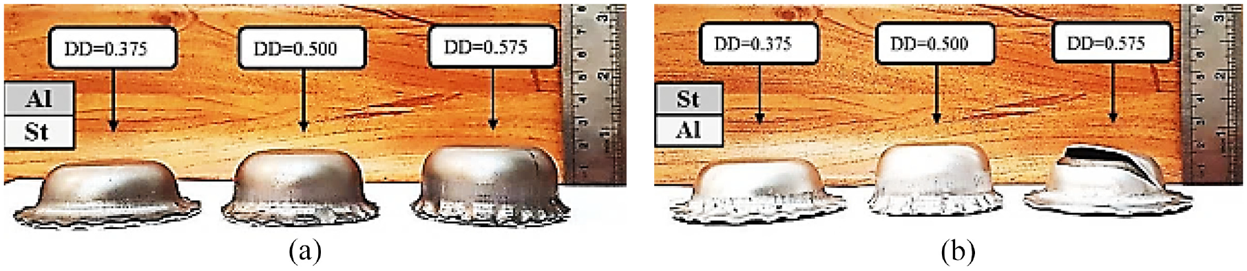
The bimetallic samples deformed up to different DDs with the: (a) Al/St and (b) St/Al layer sequence.
Figure 7 shows the variations of the maximum thickness strain and thickness variation for drawing depths of 0.375 and 0.500 and Al/St and St/Al bimetallic sheets. Knowing the higher strength and elongation of the steel compared with aluminum (Figure 1), one can reasonably conclude that with either layer sequence, the steel sheet experiences a smaller (εth)max and, consequently, a lower Vth compared with the aluminum layer. Regarding the layer sequence, the maximum thickness strain and the thickness variation of the aluminum experienced a considerably larger increase than those of the steel sheet. An overall comparison of the maximum thickness strain and thickness variation of the bimetallic specimens shows that, for different drawing depths, due to the higher strength and elongation of the steel layer compared with the aluminum sheet, the Al/St composite cup possesses a higher uniformity and a smaller maximum thickness strain than the St/Al one. This point is confirmed by Figure 7. A comparison between diagrams of Figure 7 reveals that by increasing the DD ratio from 0.375 to 0.500, in the Al/St layer sequence, the maximum thickness strain and thickness variation are increased by 51% and 25% for the aluminum sheet and 40% and 26% for the steel layer, respectively. This figure also indicates a greater increase in thickness strain of the aluminum layer compared with the steel sheet. Based on Figure 7(b), the final thickness variation for aluminum and steel was, respectively, 2.40 and 1.79 for drawing depth of 0.375; as well as 2.99 and 2.25 for drawing depth of 0.500. These values imply a higher uniformity of the steel in comparison with the aluminum sheet for both the drawing depths of the Al/St layer sequence. The diagrams of Figure 7 also illustrates that by increasing the DD from 0.375 to 0.500 for the St/Al stacking sequence, (εth)max and Vth are respectively increased by 61% and 39% for the aluminum sheet; and by 34% and 15% for the steel layer.
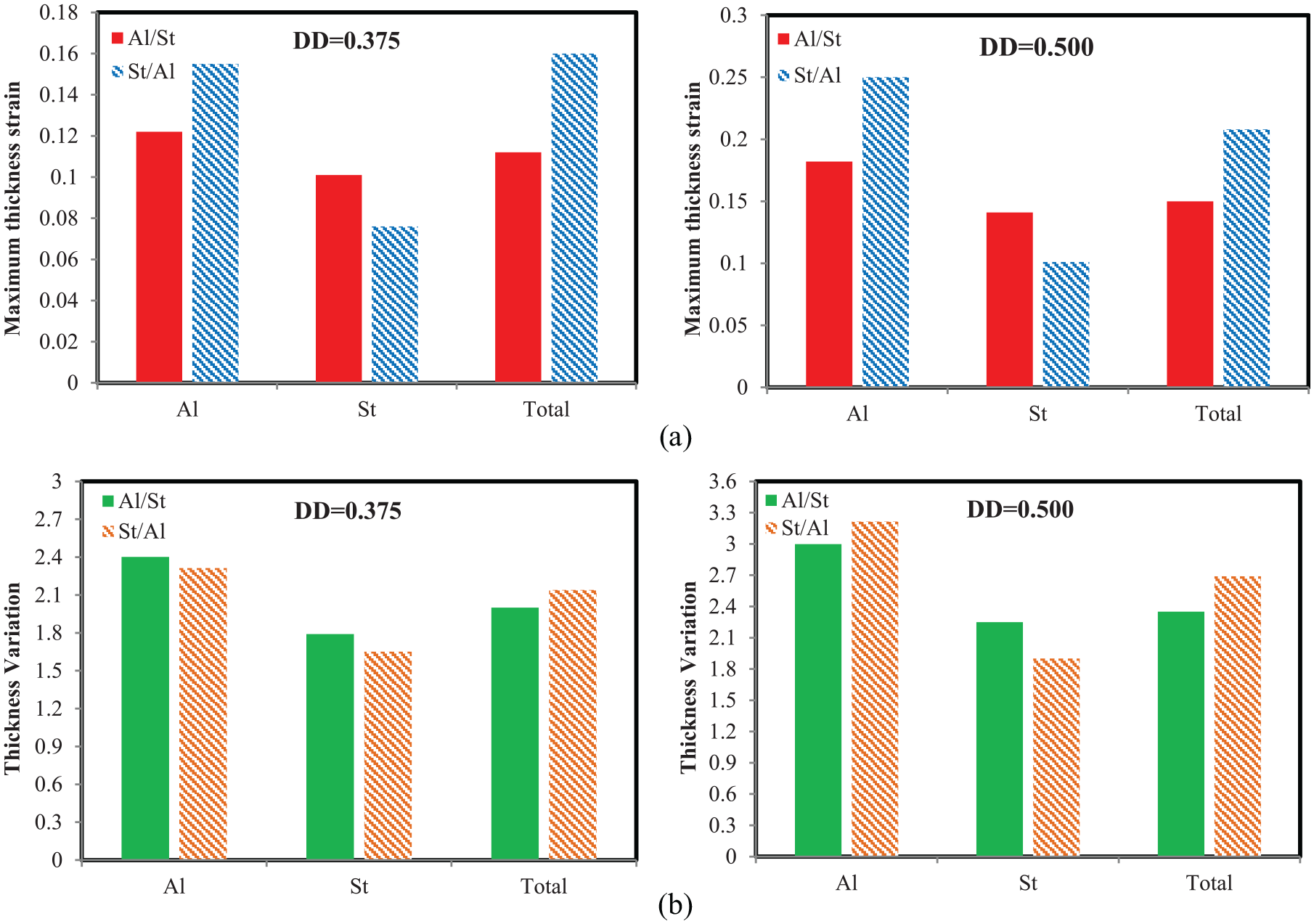
Changes in: (a) maximum thickness strain and (b) thickness variation for composite cups (Al/St and St/Al) and different drawing depths.
The effect of fluid pressure
The fluid pressure inside the die cavity is another effective parameter of the HMDD process. The mechanism of applying the pressure in the practical tests is such that by moving the punch downwards, the oil in the container underneath the blank is compressed up to a specific level. Afterward, a safety valve is opened and the excess pressure is released. This contact pressure of the fluid is also modeled in the FE simulations. It should be noted that the maximum pressure was assumed to be 0 (conventional deep drawing), 50, 150, and 250 bar, and the maximum thickness strain and thickness variation were calculated for the total thickness of the bimetallic component. The drawing depth (DD) of the specimens was also considered to be 0.500. The pressure paths used for performing the HMDD process in the present investigation are illustrated in Figure 8.
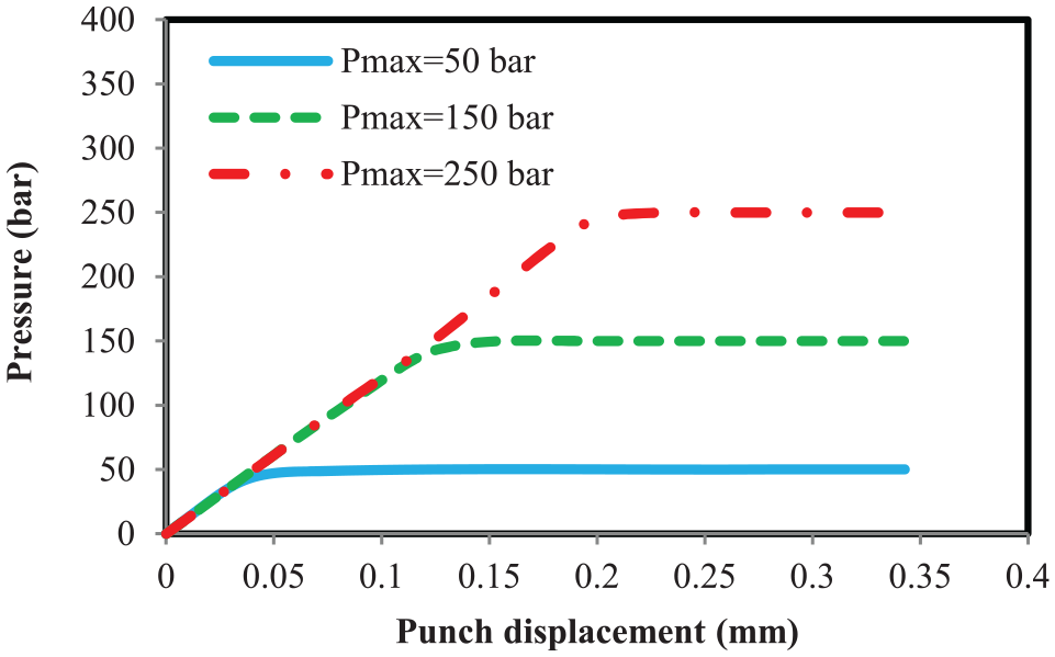
The pressure-punch displacement diagrams for various HMDD tests.
The bimetallic specimens produced with St/Al and Al/St layer sequences and die pressures of 50–250 bar together with the maximum thickness strains and thickness variations calculated for these samples are illustrated in Figure 9.
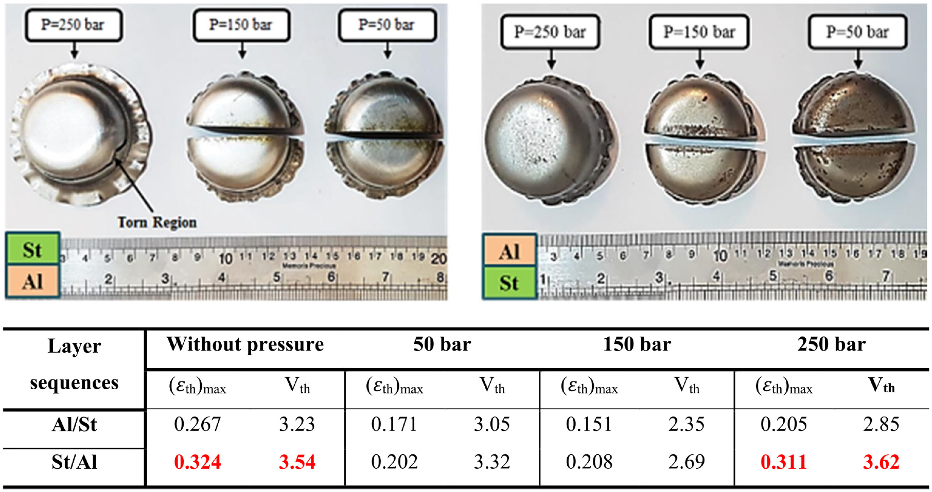
Bimetallic specimens produced by the HMDD operation under different fluid pressures.
In the present study, a fluid medium is used to eliminate the stress concentration at the sheet–punch tip contact area, acting as a holder under the sheet and uniformly distributing the force exerted on the specimen over the lower surface of the sheet. Accordingly, compared with the HMDD process, the conventional deep drawing is expected to represents higher values for (εth)max and Vth or even, in the worst case, the sheet could be torn. These points are confirmed by the results summarized in Figure 9. The maximum impact of the change in the fluid pressure inside the die cavity on the variation of thickness strain is related to the corner and wall of the final cup. At the corner area, the blank is bent and stretched simultaneously, and this can cause relatively large strains at this region. The maximum compressive stress, instead, is created in the flange and wall regions of the product. The results are demonstrated in Figure 9 suggest that for the Al/St layer sequence, by increasing the container pressure from 50 to 150 bar and from 150 to 250 bar, the maximum thickness strain reduced by 12% and increased by 36%, respectively, whereas the thickness variation, respectively, reduced by 23% and augmented by 21%. On the other hand, in the case of the St/Al arrangement, by increasing the maximum pressure from 50 to 150 bar, (εth)max, and Vth respectively increased by 3% and reduced by 19%. For this sequence, the product was torn at 250 bar. Although the fluid under the sheet can prevent the tearing of the product, increasing the fluid pressure above a certain limit degrades the product as this is the case in the current investigation for the St/Al layer sequence at the maximum pressure of 250 bar. The increase in (εth)max due to changing the maximum fluid pressure from 50 to 150 bar was not too high to cause rupture in the St/Al drawn cup. On the other hand, the thickness variation index was noticeably improved in this interval. For this reason, the better values of maximum fluid pressure for the remaining of the present research were considered to be 150 bar. Experimental findings about the changes in the maximum fluid pressure revealed that the bimetallic specimen with the Al/St stacking sequence offered a better quality in comparison with the St/Al arrangement.
The effect of process temperature
The process temperature is an important variable in metal forming. Many metals, in particular lightweight alloys such as Mg alloys, cannot easily be formed at room temperature and require elevated temperatures for plastic deformation. With this regard, this section presents the results of HMDD of Al/Mg and Al/St composite materials at the room and elevated temperatures for different drawing depths. AZ31B magnesium alloy sheets were also employed for this part of research. Because of its lightness and unique properties, this alloy is widely employed in various industrial applications. The main shortcoming of AZ31B is its weak corrosion resistance. That is why it should be used with a corrosion resistant alloy such as aluminum. Figure 10 demonstrates the Al/Mg and Al/St composite cups produced at different temperatures with various drawing depths. As is evident from this figure, the double layered Al/Mg sample was torn during the process as a result of the brittleness of magnesium at the room temperature. Also, Figure 10 illustrates the changes in the maximum thickness strain and thickness variation of the two specimens at 200°C for two drawing depths (0.375 and 0.500) and Al/Mg and Al/St layer sequences. It should be noted that the maximum fluid pressure was about 150 bar for all the experiments listed in Figure 10. By increasing the process temperature, the ductility of the blank is improved and this, in turn, facilitates its localized necking and results in greater variations in the thickness of the final product. By this means the dimensional accuracy of the deformed part is decreased. As can be observed from Figure 10, the bimetallic Al/Mg specimen was successfully formed at 200°C without tearing. Increasing the temperature in the forming process reduces the yield stress of the material and enhances the drawability. However, this remedy also reduces the dimensional accuracy of the product. A comparison between the results presented in Figures 9 and 10 implies that by elevating the temperature of the forming operation of the Al/St specimen from the room temperature to 200°C, (εth)max, and Vth of the deformed part increased by 68% and 18%, respectively. Furthermore, by comparing the findings obtained for the two drawing depths, elevating the process temperature resulted in a larger negative influence on the maximum thickness strain, in comparison with the thickness variation. For instance, an increase in the drawing depth of the Al/St specimen from 0.375 to 0.500 increased (εth)max and Vth by 75% and 26%, respectively. With increase in drawing depth from 0.375 to 0.500, the maximum thickness strain and thickness variation in the final product with Al/Mg layer arrangement increased by 56% and 16%, respectively. A comparison between the thickness variations of the Al/Mg and Al/St products also indicated that these variables were smaller for the former one, regardless of the drawing depth. Moreover, the value of Vth and its percentage increase due to variation of the drawing depth from 0.375 to 0.500, were lower for the Al/Mg cup compared with the Al/St specimen. This is justifiable considering that the flow behavior of the aluminum alloy under consideration is more similar to that of the magnesium alloy than the steel sheet.
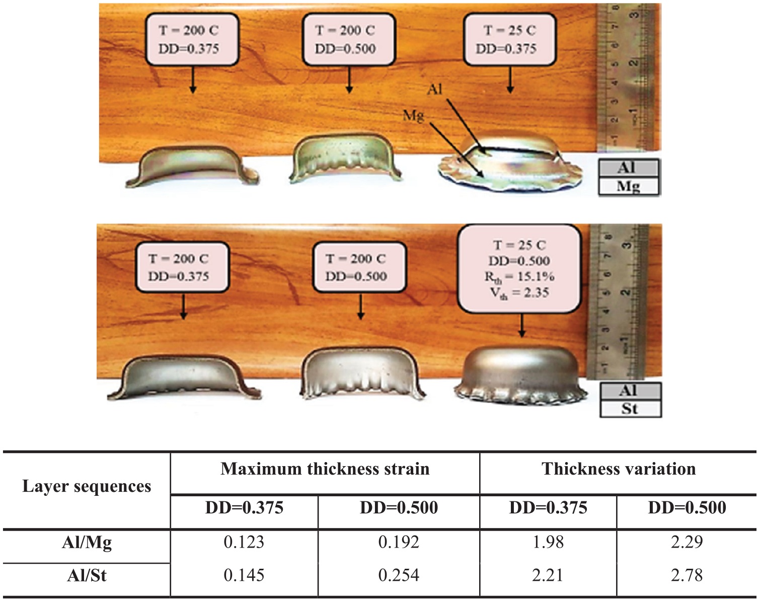
The effect of the process temperature on the production of composite specimens with Al/Mg and Al/St stacking sequences.
Conclusion
The hydro-mechanical deep drawing process of bimetallic specimens including 1200 aluminum, St13 steel, and AZ31B magnesium alloys was experimentally and numerically investigated. The parameters considered for the room temperature included the layer sequence, drawing depth, and the maximum fluid pressure in the die cavity. The effect of the temperature on the forming process was also studied for both the Al/Mg and Al/St specimens. The maximum thickness strain and thickness variation were assumed to be measures of the quality of the final product. Accordingly, the most remarkable conclusions of the present research work are listed below:
The HMDD experiments conducted and the related DOE analysis revealed that the drawing depth, the layer sequence and the fluid pressure sequentially had the greatest effects on the uniformity of the final product. For the bimetallic aluminum-steel specimen, the experimental findings illustrated that the Al/St layer sequence offered a higher quality compared with the St/Al arrangement under the same process conditions.
Based on the DOE analysis, the optimum fluid pressure was found to be 150 bar to achieve the best quality of the composite cup. Moreover, a minor interaction between the drawing depth and the fluid pressure was observed for the HMDD process.
The fluid pressure underneath the sample can prevent tearing. However, the product loses quality by excessively increasing this parameter. The maximum thickness strain increases and, at the same time, the thickness variation decreases by intensifying the fluid pressure in the die cavity. Despite the increase in the maximum thickness strain for fluid pressures between 50 and 150 bar (in St/Al stacking sequence), the value of this variable was not that high to cause a rupture in the product and even the thickness variation improved notably.
Increasing the temperature of the forming process reduces the yield stress of the material, facilitating its plastic deformation at the expense of dimensional accuracy. A comparison between the thickness variations of the Al/Mg and Al/St specimens showed that this parameter was smaller for the former one, regardless of the drawing depth. This point is reasonable considering that the flow stress and elongation of aluminum are closer to those of magnesium than the steel layer.
Footnotes
Declaration of conflicting interests
The author(s) declared no potential conflicts of interest with respect to the research, authorship, and/or publication of this article.
Funding
The author(s) received no financial support for the research, authorship, and/or publication of this article.