
Abstract
Fabricating flat sandwich sheets into components with a required shape and dimensions is a challenging job in the metal forming field. In this article, hydro-mechanical deep drawing was used for sandwich sheet forming. The aim of the work is to achieve higher drawing ratio of these sheets. Theoretical, numerical and experimental analysis of the hydro-mechanical deep drawing of sandwich sheets was carried out. Separated layers theory method is used for theoretical analysis of the process. Then, the numerical simulation of the process was developed by finite element method. The effect of core layer thickness on the forming force of the sandwich sheet and effective parameters of the process such as strain and forming force was investigated. Experimental works were conducted on the steel/polymer/steel sandwich sheets by a hydro-mechanical deep drawing die. A good agreement was observed between theoretical, numerical and experimental results. The safe zone of fluid pressure for achieving a part without rupture was obtained. It was shown that the limit drawing ratio is increased by increasing the pressure but after a particular point, the limit drawing ratio is decreased by increasing the chamber pressure. It was also observed that maximum drawing ratio for achieving a part without rupture in the hydro-mechanical deep drawing process is higher than conventional deep drawing process.
Introduction
Nowadays, with the development of various industries, researchers try to find materials with a high stiffness-to-weight ratio. Sandwich sheets are made of a combination of sheet metals and a non-metallic core. The core is often made of foam, polymer, composite and so on. Sandwich sheets can have more efficiency and strength than monolayer metal sheets and production costs are also lower. Therefore, sandwich structures are widely used in industries. 1 Three-layer steel/polymer/steel sandwich composites are representative of these materials. These sheets have high strength and good formability. They also have a high capacity to absorb vibrations. In addition, using suitable steel sheets as sandwich face sheets, they can also have good corrosion properties. 2 However, producing sandwich sheets is relatively simple, and forming of these sheets has difficulties. Deep drawing is a general process used in the production of auto parts and is also used in other industries. Thus, hydro-mechanical deep drawing (HMDD) process was used for deep drawing of sandwich components. The HMDD process has become an emerging technology to produce advanced light-weight materials with complex shapes and also reduces forming steps. The HMDD process overcomes some limitations of conventional deep drawing. So by this process, deeper cups can be produced (high drawing ratio) with a more uniform cup wall thickness, higher dimensional accuracy and better surface quality. And also it can be used for the formation of complex-shaped sheet metal parts.3,4 Normally, the HMDD process includes two steps: (1) pre-bulging step, in which blank is bulged by initial pressure and (2) drawing step with applied controlled pressure. In the second step, a punch draws the blank into a chamber that has been filled by a controlled fluid (generally oil) as the female die as shown in Figure 1. In this process, two blank holder systems can be used: with a specific force or a fixed gap system. 5 In the latter one, which is used in this research, the blank holder is placed at a constant distance from the die. In this case, because of increase in thickness in the flange region, the fixed blank holder prevents the wrinkling of the sheet in this region. And in the case of high pressure, the sheet is not in contact with the die and it is pushed to the blank holder by the fluid pressure.
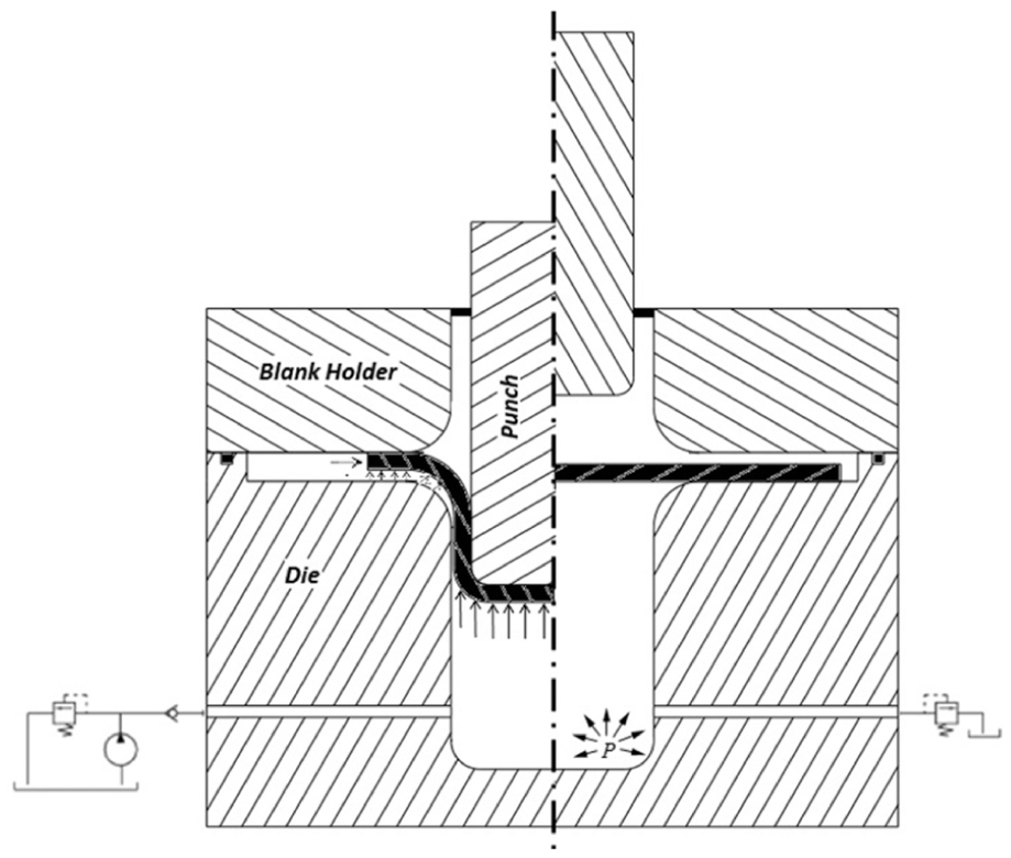
Schematic illustration of HMDD process: (right) initial setting of the process and (left) during the process.
Hydroforming is mainly divided into two fields: sheet hydroforming and tube hydroforming. Many former works have focused on tube hydroforming.6–9 Sheet hydroforming technology began before World War II, and the HMDD was found in 1890. The great progress in this process was in the 1960s and 1970s, and this process was used in the production of auto parts and aircraft in 1980. In recent years, new works have been done in this field, mainly in Germany and Japan. 10 Many works have been done on different types of sheet hydroforming.11–13 Yossifon and Tirosh 14 investigated fluid pressure to prevent wrinkling in the flange area for deep drawing process by fluid pressure as blank holder force (BHF). Results show that for wrinkling investigation in the flange area, maximum pressure is required at different heights to prevent rupture. Fazli and Dariani15,16 applied simulation and parametric study on HMDD. In this study, the process was modeled based on the assumption of cylindrical parts with strain hardening and anisotropy for single-layer sheets of aluminum. Bagherzadeh et al.3,17 conducted both theoretical and experimental studies on HMDD of bimetallic sheets. In this study, safe zone and rupture zone are presented in the HMDD process for an aluminum-steel sheet. Kim et al. 18 studied formability of sandwich sheets with aluminum face sheets and polymeric core. In this research, forming limit diagram of aluminum/polymer/aluminum sandwich sheets was obtained through improved M-K theory that was in good agreement with the experimental results. It was also shown that if the polymeric core sheet can have a greater strain hardening exponent, formability of sheet improves. Also, Hashemi and Karajibani 19 investigated the formability of two-layer sheets through M-K theory. Parsa et al. 20 conducted a theoretical and numerical investigation on spring back of aluminum/polymer/aluminum sandwich sheets after forming. The results show that by increasing the thickness of the sandwich plate (which is caused by an increase in thickness of core), the spring back is increased. Morovvati et al.21,22 studied the wrinkling of the single-layer and two-layer sheet metals in the conventional deep drawing process. They investigated the effect of BHFs on wrinkling and fractures in drawing process of single and two layers. Results show that the optimum BHF for two-layer sheets is affected by the material and arrangements of lay-ups. Pourmoghadam et al. 23 conducted bifurcation analysis on the wrinkling of the aluminum/polymer/aluminum three-layer sandwich sheets in the conventional deep drawing process. In the analytical model, plastic bifurcation based on the large deformation theory for an anisotropic sheet was used to predict the onset of wrinkling. They achieved optimum BHF in sandwich sheets forming. Also, many works have been done on wrinkling of sheet in hydroforming processes.24,25 Harhash et al. 26 studied the mechanical behavior of steel/polymer/steel sandwich sheets. In this research, the effect of thickness of polymeric core sheet on the mechanical properties was investigated. Other works have been done on steel/polymer sandwich sheets with local inlays. 27 Zhang et al. 28 investigated the thinning and spring back of multilayer metal forming using HMDD. They studied the variables such as pre-bulging pressure and pre-bulging height to optimize the forming conditions. Results show that hybrid parts produced using multilayer forming can expand the application areas of fiber metal laminates (FMLs).
In this article, parameters of the HMDD process of steel/polymer/steel sandwich sheets such as critical pressure in the fluid chamber and drawing ratio are investigated. Also forming force of process and strain is analyzed. Experiments of the HMDD process are carried out using an HMDD die. A numerical model is developed for prediction of rupture during the hydro-mechanical process and for investigating of the effect of core thickness on forming force of sandwich sheets. Moreover, a theoretical approach is used to estimate the safe zone. The numerical and theoretical results obtained are discussed and compared with the experimental results.
Experiments
For determining the mechanical properties of the materials, standard tensile tests were performed. Then, the three-layer sandwich samples were prepared using a hot press process. Finally, using an HMDD die and according to the designed experiments, sandwich sheets were tested in various conditions.
Tensile tests
In this study, the material of face sheets is low carbon stainless steel 316L and core sheet material is polypropylene (PP). In order to determine the mechanical properties of the steel sheets and the sandwich sheets, standard tensile test samples were prepared according to the ASTM-E8M. And to determine the mechanical properties of the polymeric sheet, samples were prepared according to the ASTM-D638. To investigate the effect of anisotropy, samples of the steel sheet and the sandwich sheet were prepared in the rolling direction (0°), perpendicular to the rolling direction (90°) and in the direction (45°) to the rolling direction. Figure 2 shows the obtained stress–strain diagram of the 316L stainless steel, PP and the steel/polymer/steel three-layer sandwich sheet. As can be seen, the sandwich sheet has properties between the polymeric sheet and the steel sheet.
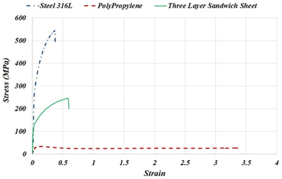
True stress–strain diagram of 316L stainless steel, PP and three-layer sandwich sheet.
The obtained mechanical properties are shown in Table 1 (see also Appendix 3).
Mechanical properties of the steel 316L skin and PP core at room temperature.
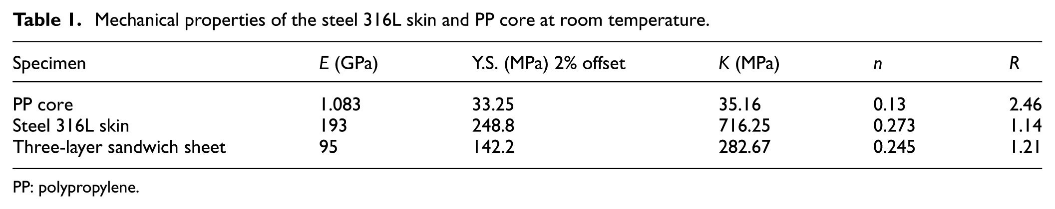
PP: polypropylene.
Three-layer samples preparation
First, to eliminate contaminations, the samples were washed with acetone. Then, the surfaces were subjected to sandblast for a mechanical lock. For bonding the steel layer to the PP layer, polypropylene maleic was used as an interface layer. For production of the adhesive film, polypropylene maleic granules were placed in the hot press at a temperature of 170 °C and a pressure of 50 bar. Then, the three-layer samples were placed in the hot press for 10 min at 190 °C and a pressure of 50 bar. The thickness of each steel face sheet was 0.5 mm and the thickness of PP core layer was 1 mm. So in order to control the thickness of the sandwich sheet, a steel frame of 2-mm thickness was used in the hot press to restrict the punch movement and retain the sandwich sheet thickness on 2 mm. Figure 3 shows the procedure of shaping of sandwich samples.
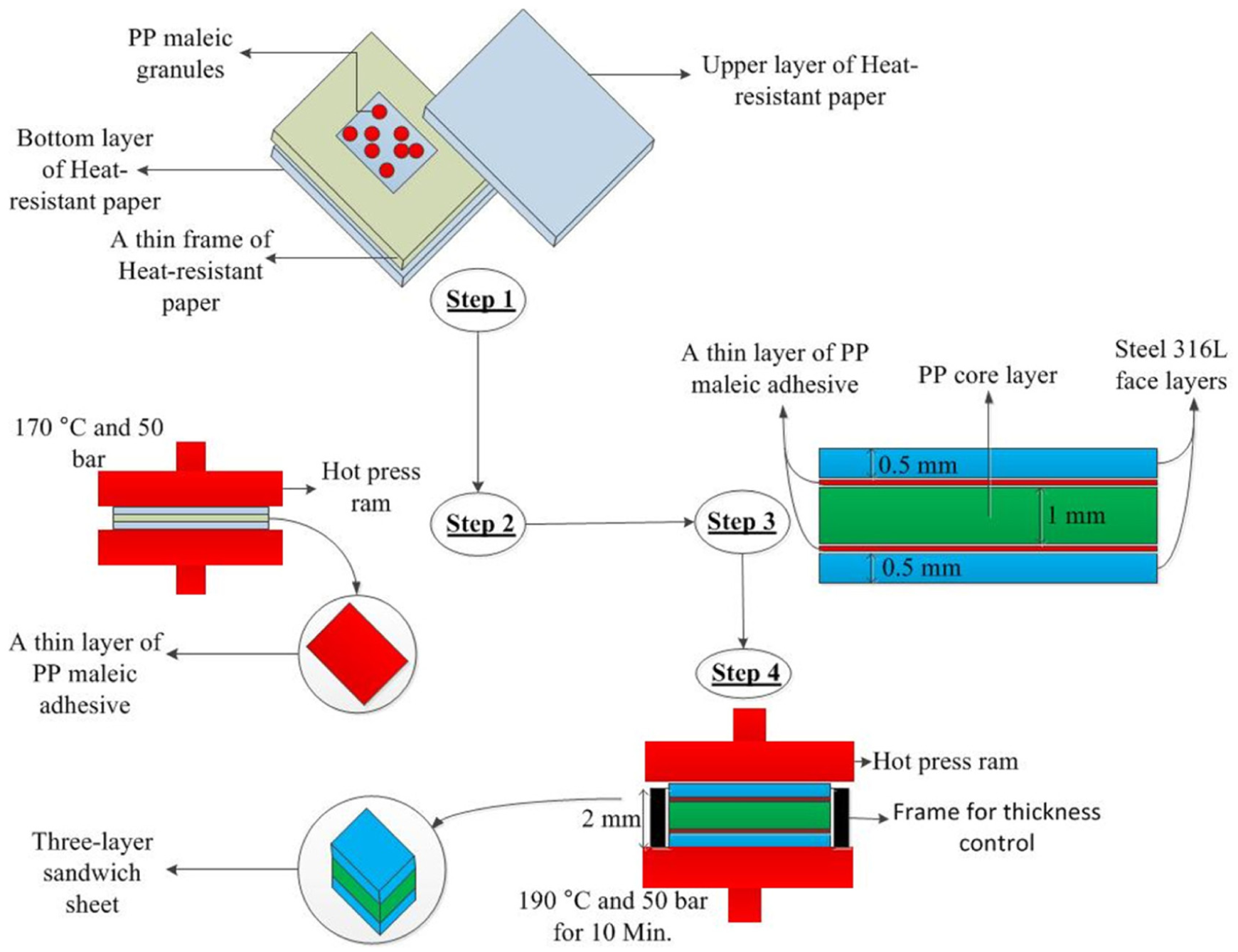
Production of sandwich sheet samples. Step 1: placing PP maleic adhesive granules between heat-resistant papers; step 2: putting the papers in hot press machine to obtain a thin layer of PP maleic adhesive; step 3: placing adhesive layers between core and face layers; step 4: putting the main layers with adhesive layers in hot press machine and using a frame to thickness control to obtain three-layer sandwich samples.
HMDD tests
As shown in Figure 1, to start the operation initial pressure valve is in the open position. And initial pressure is set for bulging stage. Pressure control valve is set for the final fluid pressure in the chamber. After the sheet bulges and reaches the setting pressure, the initial pressure valve was closed. Punch movement was done by a hydraulic press. In this case, sheet was formed with an increase in fluid pressure to the nominal final pressure inside the pressure chamber. Operation continues as far as the forming force on the hydraulic press machine monitor shows a sharp drop. Finally, the pressure inside the chamber caused the punch to come out. After discharging the pressure of the die, the shaped sandwich cup was pulled out. Figure 4 shows the HMDD equipment and hydraulic press.
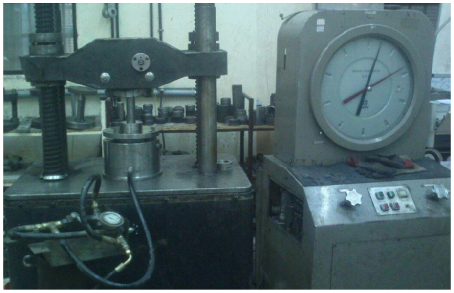
HMDD equipment and tooling.
For this work, drawing ratios of 1.9, 2, 2.1 and 2.2 and hydraulic pressures of 0 (conventional deep drawing), 50, 100, 150, 200, 250 and 350 bar were chosen in order to investigate the effect of hydraulic pressure on the limit drawing ratio (LDR) of sandwich sheets. This selection was based on the previous works3,17 and also on the finite element results.
In Table 2, the geometric parameters of the die and thickness of each layer are presented.
Geometric parameters of HMDD process.
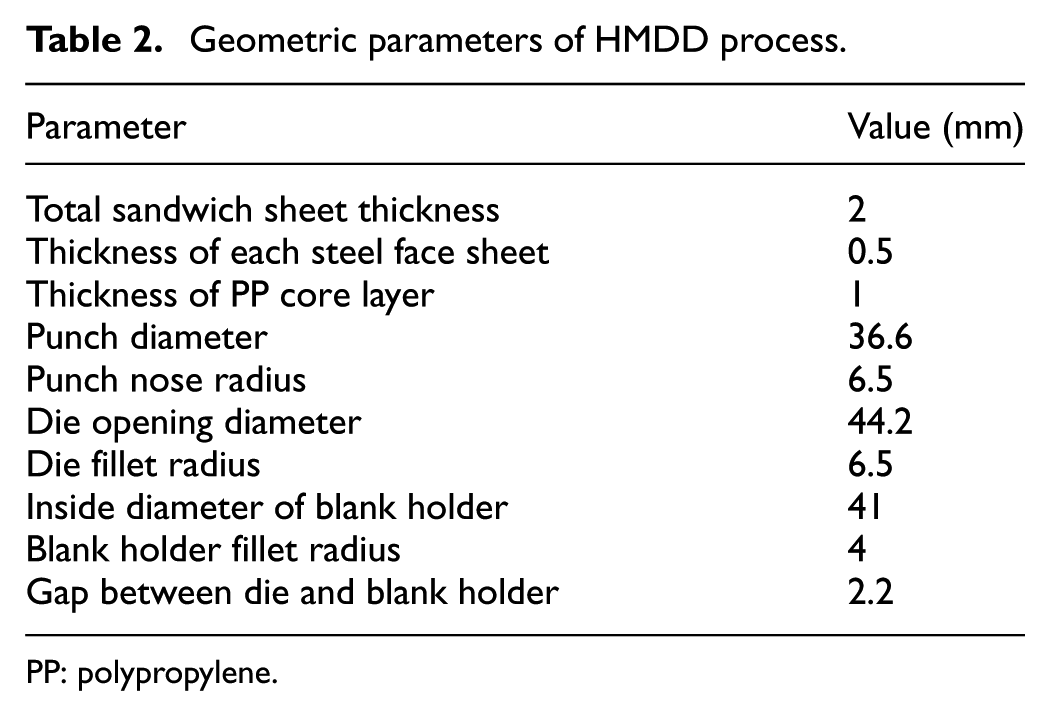
PP: polypropylene.
Finite element analysis
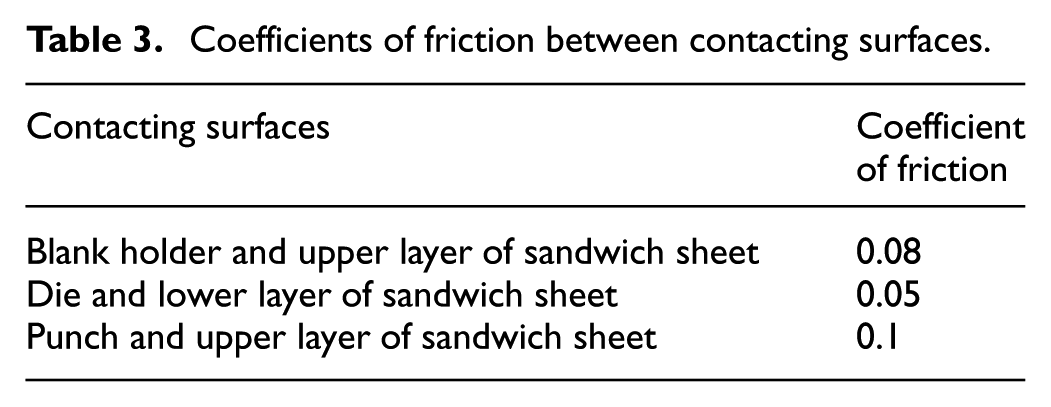
Modeling of HMDD process was developed using Abaqus/CAE. Commercial explicit software of Abaqus was used in the three-dimensional (3D) simulation. Considering the symmetry and in order to shorten the time of simulation, only 1/4 of the die and blank was modeled. Blank was modeled as deformable part and the blank holder, die and punch were modeled as discrete rigid parts. Mechanical properties of polymeric sheet and steel sheet were entered in the software as the elastic-plastic model. For this simulation, dynamic-explicit solver was used for process analysis. In this simulation, all contact surfaces are of steel material but with different lubrications. Using Coulomb friction theory, since the punch is involved in conventional lubrication with the upper face sheet, its coefficient friction is 0.1. And due to the fluid penetration into the flange area, the coefficient friction between blank holder and the upper layer of sandwich sheet is 0.08. And also due to the fact that fluid is between the die and the lower layer of sandwich sheet, these contact surfaces are completely lubricated and its coefficient friction was considered to be 0.0516–33 (these coefficients are estimations based on the literature). The applied friction coefficients between the surfaces are shown in Table 3.
Coefficients of friction between contacting surfaces.
All the sheet elements are 3D, solid, linear square mesh (C3D8R), except for the center of the sheet. In the center of the sheet, tetrahedron elements (C3D4) were used because the thickness does not change or changes negligibly in this area. In the punch radius area and die radius area, smaller elements were used in the sheet, due to the bending and unbending deformations. Figure 5 shows the final meshed model for simulation, loads and supports applied to the simulation model and also convergence result to obtain proper mesh size. As can be seen from Figure 5(b), finite element method (FEM) loads include chamber pressure under the blank and punch movement in the z-direction. Die and blank holder movements have been restricted in all directions. And also the blank has been considered to be symmetric in x and y directions. Figure 5(c) shows the convergence result. The force in a specific element was considered to obtain this convergence result. The proper mesh size that is obtained from this result is 0.5.
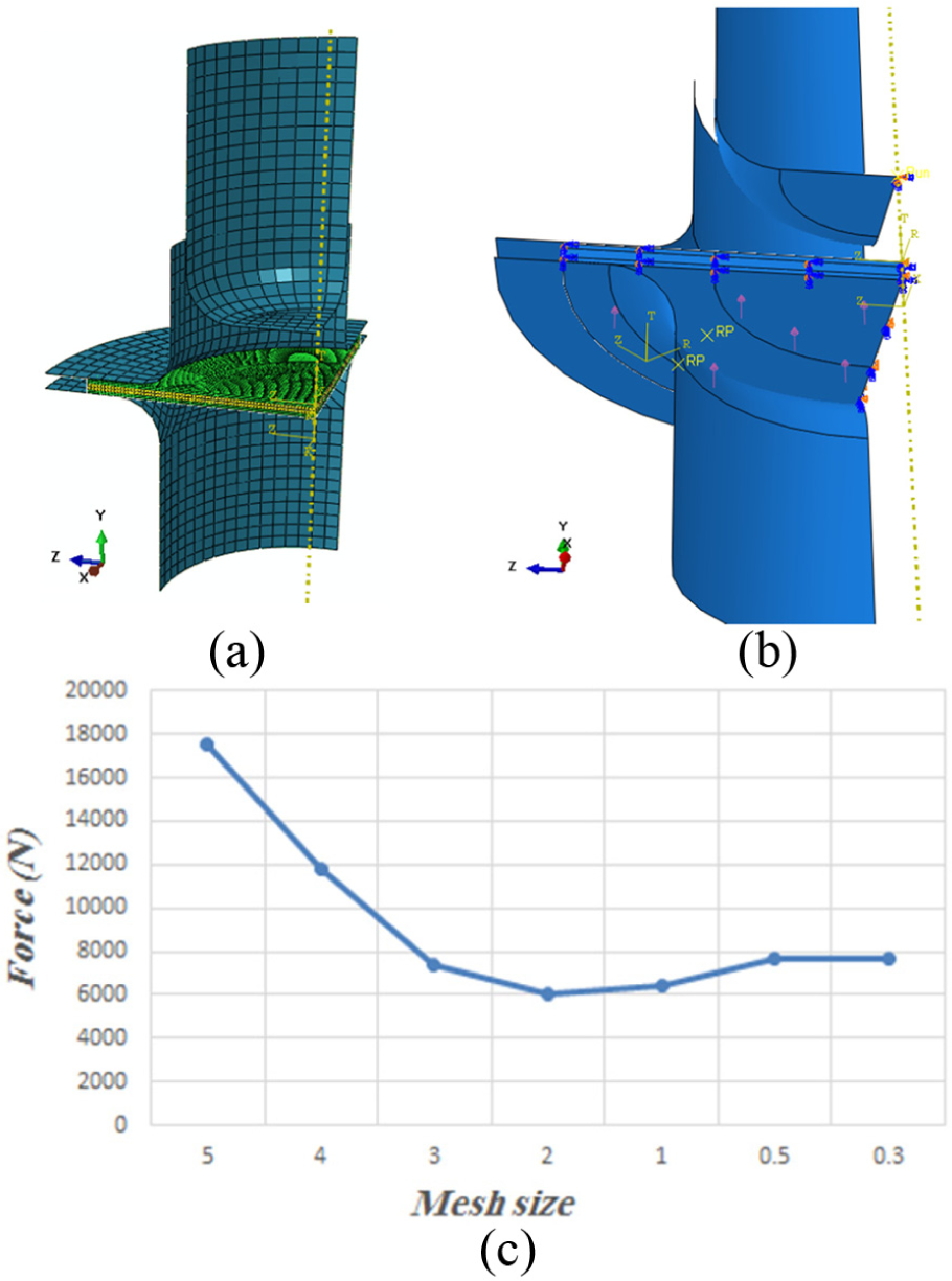
Final model for FEM simulation: (a) final meshed model, (b) loads and supports applied to the model and (c) convergence result to obtain proper mesh size.
In this work, 22 simulations were performed with drawing ratios of 1.8, 1.9, 2, 2.1 and 2.2 and hydraulic pressures of 0 (conventional deep drawing), 50, 100, 150, 200, 250, 300, 350, 400 and 450 bar.
Finally, these simulations culminated in obtaining the border of the safe zone for hydraulic pressure to determine that whether a drawing sample at a specific pressure with a specific drawing ratio would be with or without rupture. And process parameters were studied through the simulations such as applied strains and forming force. And also influence of the hydraulic pressure, drawing ratio and thickness of the polymeric core on the forming force was evaluated.
Theoretical approach
In order to investigate the plastic instability of sandwich sheet during HMDD process, two analytical models were used. 3 The first approach is separated layers theory (SLT) that is based on the mechanical properties of each component layers separately. The second analytical model is equivalent layers theory (ELT), in which the sandwich sheet is considered as a one-layer sheet with equivalent mechanical properties. In the second approach, the mechanical properties of equivalent layer were obtained by ASTM standard tensile test on sandwich samples. Among the effective parameters of the HMDD process, safe fluid pressure is very important and should be determined to prevent rupture. Final fluid pressure is adjusted to the final pressure valve. For analyzing the HMDD process using ELT method, equivalent mechanical properties of sandwich sheet were considered as properties of a one-layer metal sheet.15,34 The stress analysis of the HMDD process in the SLT method is presented in the following. In order to determine the critical pressure, the one-quarter section of the cylindrical cup was considered to be divided into three sections including flange region (I), die curvature (II) and cup wall (III) in Figure 6.
Schematic model of various regions of sheet during HMDD (drawing step).
Flange region (zone I)
In order to analyze the HMDD process of the sandwich sheet, a radial element was utilized in this zone as shown in Figure 7.
Radial element of sandwich sheet in flange region (zone I).
Considering the equilibrium equations for each layer and Barlat–Lian yield criteria based on Bagherzadeh et al. 3 and developing the equations to the three-layer sandwich sheets, radial stress in the flange region is (see Appendix 2)
where the parameters are defined as following
where r0 is initial radius of an arbitrary point in the flange region that has moved to the current position with radius r, b is the outer radius of flange, ρ is the sandwich blank curvature, P1 is the chamber pressure, t is thickness, K is strain hardening coefficient of material, n is strain hardening exponent of material, c is anisotropy coefficient in the Barlat–Lian non-quadratic yield criteria and indexes s, p and c indicate steel layer, polymer layer and composite sheet, respectively.
According to the volume constancy assumption during HMDD process, the relation between r0 and r in flange region can be achieved as 3
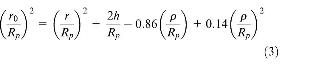
Also, the current radius of flange edge is calculated as
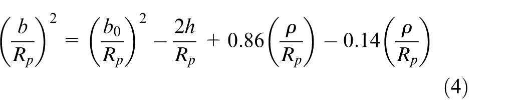
where b and b0 are the initial and current radius of flange edge and the parameters Rp and h are punch radius and current cup height, respectively.
Die curvature region (zone II)
In this region, a radial element as shown in Figure 8 was utilized.
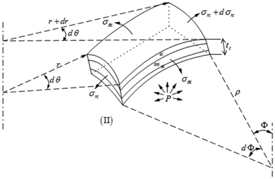
Radial element of sandwich sheet in die curvature region (zone II).
Assuming that the sheet is in floating condition, and using equilibrium equations based on Bagherzadeh et al. 3 and developing the equations to the three-layer sandwich sheets, radial stress was obtained as below (see Appendix 2)
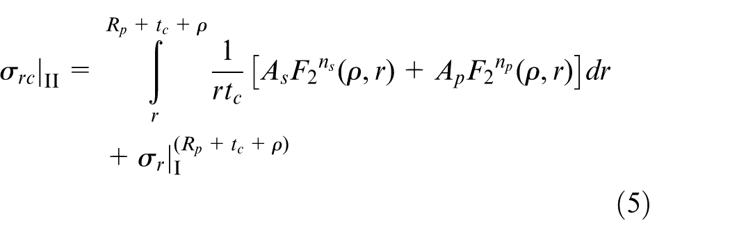
where r is the current radius in zone (II) and the other parameters are similar to equations (1) and (2). Also, the sandwich sheet strain with respect to initial and current radius is
The relation between initial radius r0 and current radius r of one point in the zone (II) is defined by volume constancy assumption as
Also, the blank curvature (ρ) in hydroforming deep drawing process is determined by the following equation 14
Critical pressure in plastic instability
Plastic instability can occur in layers by increasing pressure. Regarding Swift’s instability law and using instability conditions of Barlat–Lian yield criteria based on Bagherzadeh et al. 3 and developing the equations to the three-layer sandwich sheets and assuming that the instability occurs in steel layer (that is a true assumption in practice), instability condition can be determined as follows (see Appendix 2)
where αs and αp are constants related to Barlat–Lian anisotropy coefficients of steel and polymer layers, respectively, and are determined as following
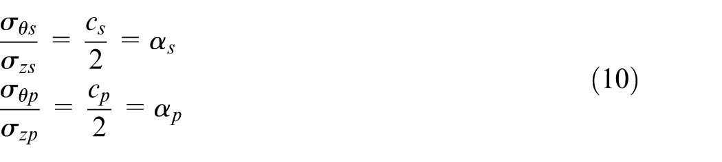
And Ss and Sp are the sheet thickness ratios of steel and polymer layers, respectively.
Using equations (8) and (9) and using numerical integration method, critical pressure was obtained by MATLAB software (see Appendix 2).
Results and discussion
In this research, plastic instability of HMDD of sandwich sheets was studied by SLT method and all theoretical results were obtained by this method. Simulations were performed with various drawing ratios and hydraulic pressures for 316L/PP/316L sandwich sheets, and experiments were conducted to verify the theoretical and numerical results. Following results are presented for safe zone of fluid pressure, forming force and strains.
Safe zone of fluid pressure
Using the developed finite element (FE) model, the rupture and wrinkling of the HMDD of sandwich sheets were predicted at various drawing ratios and fluid pressures. The pre-bulging pressure was constant and equal to 20 bar. As shown in Figure 9 in the performed simulations, drawn samples with and without rupture have been indicated with distinguishing marks. Then, according to these points, the boundary was marked by a curve. It is an approximate curve specifying the boundary between the points with and without rupture obtained from simulation results which is the fitted curve to the points. As can be seen, the LDR is increased by increasing the pressure up to 150 bar, but after 150 bar, the LDR is decreased with the increase in pressure. Maximum LDR at 150 bar is 2.15, while in conventional deep drawing, it is about 1.9. Thus, the formability of these sheets is increased about 15% in HMDD process. In fact, without fluid pressure in chamber (conventional deep drawing), rupture occurs in the edge of punch, due to the contact between sheet and die edge (non-floating condition) and increase in friction and tensile stresses. With exerting fluid pressure floating condition occurs and tensile stresses are decreased and it results in obtaining sample without rupture. But when the pressure is higher than a certain amount, rupture occurs near to the die edge. This phenomenon is because of the extreme contact between punch and sheet and creation of a curvature with a small radius in the die edge. So the formability is best at some optimum pressure.
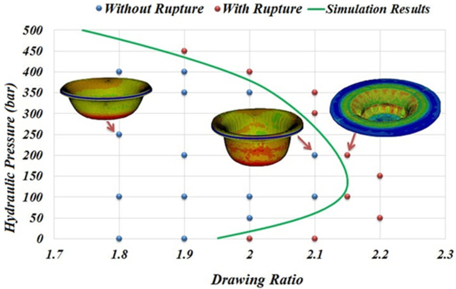
FEM results for determining the safe zone of hydraulic fluid pressure of the process for sandwich sheet in different drawing ratios.
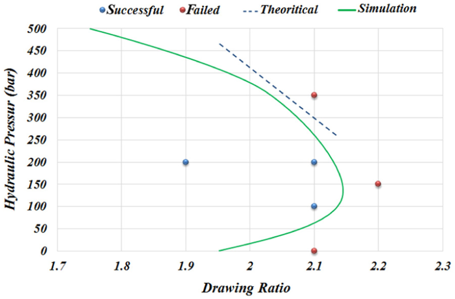
Figure 10 shows the experimental results for the safe zone of fluid pressure for steel/polymer/steel sandwich sheet. Points inside and outside the curve are the results of HMDD tests, and the sketched curve is the result of finite element simulation. For the sake of time and cost considerations, experiments could not be carried out for all points to verify the safe zone border; so some experiments were conducted to evaluate the tendency of the influence of hydraulic pressure and drawing ratio on rupture occurrence. That being so, as can be seen increasing pressure for drawing ratio of 2.1 makes it possible to produce the cup without rupture, but when pressure increases to level of 350 bar, it can be seen that pressure increasing does not prevent rupture and actually it causes sample rupture. Also pressure increasing for drawing ratio of 2.2 could not inhibit the rupture occurrence in cup. With all these taken into account, it is true that the conducted experiment might not predict the safe zone border precisely but it is in agreement with the finite element results.
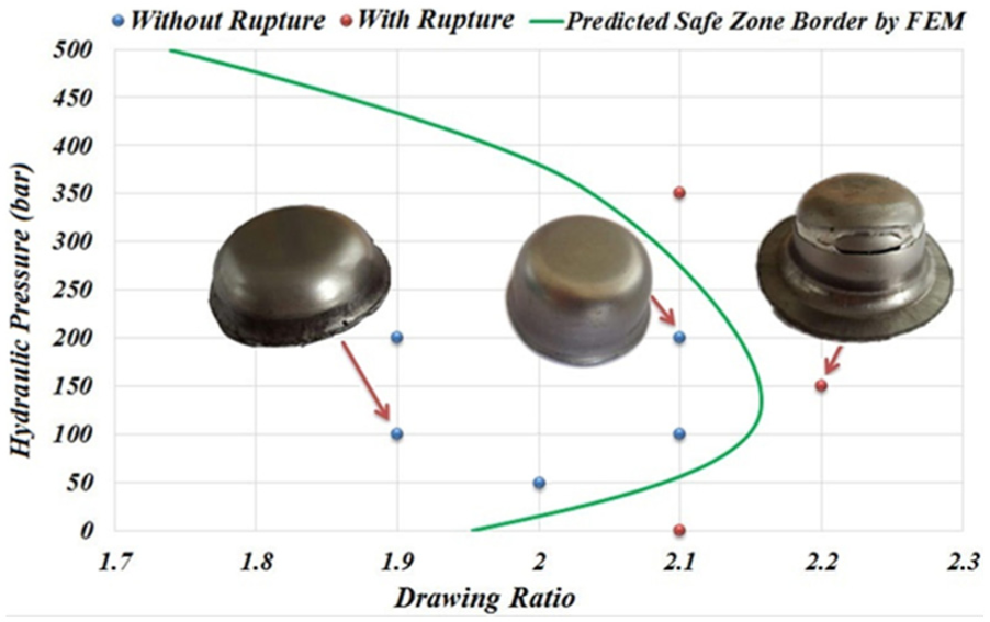
Experimental results of safe zone of hydraulic fluid pressure of sandwich sheet and comparison with predicted zone by finite element method.
Figure 11 shows the numerical simulation and experimental results for investigation of wrinkling in HMDD of sandwich sheets. It can be seen that wrinkles is eliminated by increasing the pressure. Since the blank holder is fixed at a constant distance from sandwich sheet, the chamber pressure that pushes the blank to the blank holder determines the BHF. Therefore, pressure increasing results in increase in BHF and decreases the possibility of wrinkling.
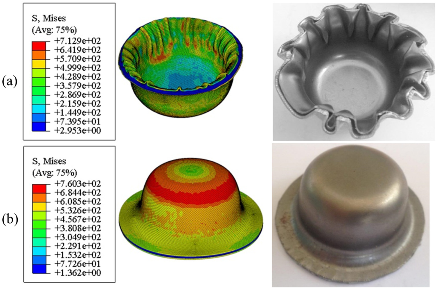
Effect of pressure on wrinkling: (a) sample with DR = 2 and pressure = 50 bar and (b) sample with DR = 2 and pressure = 250 bar (simulation and experimental results).
Figure 12 shows the prediction of rupture in HMDD process by FEM in comparison with experiments. As can be seen, finite element simulation shows a good agreement in prediction of rupture of sandwich sheet.
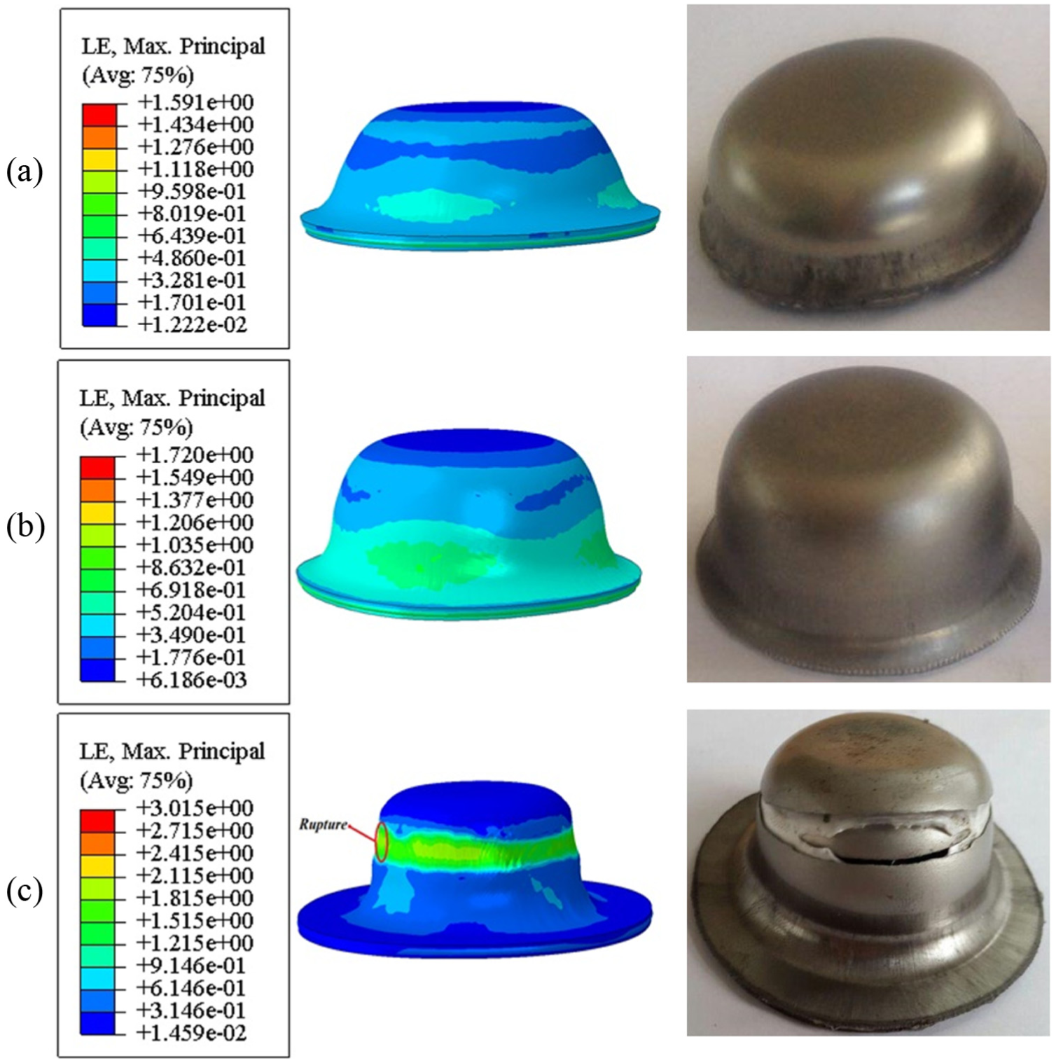
Prediction of rupture in HMDD process of sandwich sheets by FEM: (a) sample with DR = 1.9 and pressure = 200 bar, (b) sample with DR = 2.1 and pressure = 200 bar and (c) sample with DR = 2.2 and pressure = 150 bar.
Here, failure criteria for FEM results are based on overall success of the process. In this method, strain history of elements is obtained along radial path in the middle section of the model. A sudden change in the strain gradient of an element compared to the strain of other elements is considered as the initiation of rupture in that element.17,35
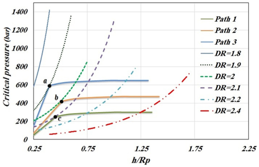
Figure 13 shows the critical fluid pressure in HMDD process for steel/polymer/steel sandwich sheets obtained from SLT. This diagram shows the critical pressure increase by increasing the depth of drawing. In this diagram, each curve represents the ultimate pressure that is higher than that when rupture occurs. The safe zone and the failure zone have been obtained for different drawing ratios. So that if the pressure of the process is placed above the curve, at a certain depth for a certain drawing ratio, rupture occurs. It can be seen that the safe zone has been limited by increasing the drawing ratio.
Critical pressure curves at different drawing ratios obtained from separated layers theory.
Increasing the pressure in the chamber to the ultimate pressure of the process is carried out according to the model that was presented by Jensen et al. 36 In order to obtain the upper limit of the applied fluid pressure in the theory analysis, the intersection point has to be obtained for the diagram of the pressure increasing in different pressures with the critical pressure curves obtained from the theory for each drawing ratio. To do this, according to Figure 13, the pressure increasing path 1 is considered such that it cuts the critical pressure curve in the drawing ratio of 2.1. Then, the pressure increasing path 2 is considered such that it cuts the critical pressure curve in the drawing ratio of 2. Similarly, different pressure paths are considered. Therefore, the intersections of chamber pressure increasing curves and the curves of the critical pressure obtained from SLT (points a, b and c in Figure 13) indicate rupture at different drawing ratios. By these points, diagram of critical pressure can be plotted for different drawing ratios (theoretical line in Figure 14).
Comparison of the maximum safe fluid pressure predicted by theory and simulation and experimental observations for sandwich sheet.
Figure 14 shows the safe zone obtained from numerical simulations and the safe zone estimated by theory and experimental results. The line obtained from the theory approach is the result of fitting a straight line to the points obtained by this method. As can be seen, the theory analysis estimates the upper limit of fluid pressure. This line actually shows the allowable increase in chamber pressure in order to impede rupture, because it is obtained from plastic instability in HMDD. But pressure increasing cannot prevent rupture occurrence in process at drawing ratios of more than 2.15. Therefore, theoretical line cannot be covered for all drawing ratio values.
Forming force
The process forming force was obtained from finite element simulation method and also was extracted from the press monitor in experiments. For this purpose, forming force of sandwich sheet with a drawing ratio of 1.8 and pressure of 250 bar was studied. Figure 15 compares the forming force obtained from simulation, theoretical approach and experimental observations.
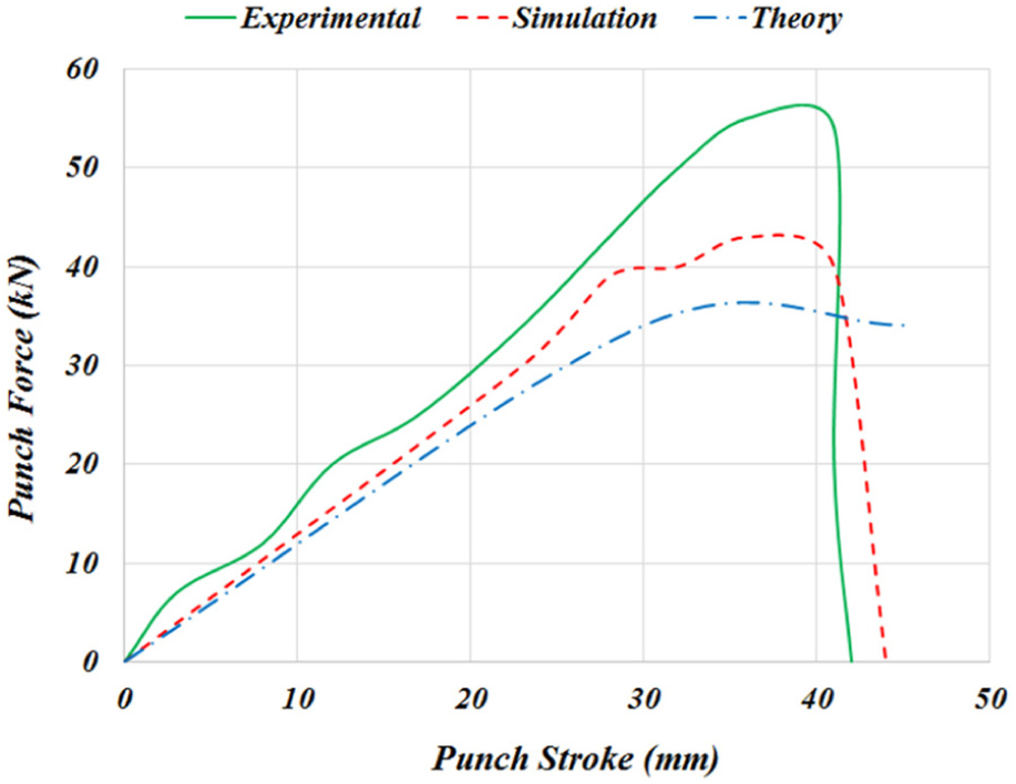
Comparison of obtained forming force from simulation, theory and experimental observations for sample with drawing ratio of 1.8 and pressure of 250 bar.
As can be seen, forming force obtained from experiments is higher than simulation and the simulation results are higher than theoretical analysis results. The average error of forming force that is predicted by finite element software is approximately 12%. This difference can be due to minor wrinkling in experimental samples. This minor (elastic) wrinkling in the flange area is omitted by the tensile stress that was applied to the sheet as a result of the material flow into the die cavity. Therefore, wrinkling could cause a change in the stress state of the wall zone and increase the forming force.21,37 The high error of theoretical analysis prediction of forming force can be due to the simplification of analytical equations to calculate the force, such as assuming constant curvature radius in drawing sheet.
Figure 16 shows changing of forming force due to the fluid pressure increasing in a constant drawing ratio of 2. As can be seen, forming force increases by an increase in fluid pressure because increasing the fluid pressure increases the necessary force to overcome this pressure to forming the sheet. Increasing the pressure from 0 to 250 bar in constant drawing ratio of 2 caused an increase of 48% in forming force.
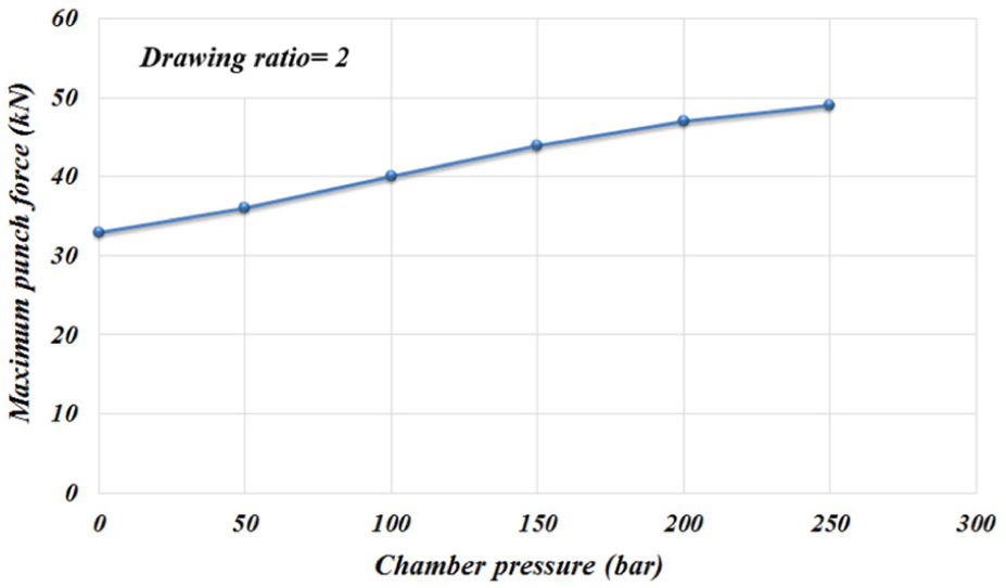
Effect of chamber pressure on forming force in constant drawing ratio of 2.
Figure 17 shows changing the forming force due to the increasing of drawing ratio in constant pressure of 200 bar. As can be observed, increasing of drawing ratio increases the forming force because of increasing the contact surface of sheet. Increasing drawing ratio from 1.8 to 2.1 in constant pressure of 200 bar increases forming force about 42%.
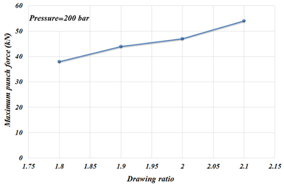
Effect of drawing ratio on forming force in constant chamber pressure of 200 bar.
FEM simulations were conducted to investigate the effect of core thickness on forming force. Figure 18 shows the numerical simulation results for effect of polymer core thickness on the forming force. As the thickness of the polymeric core layer increases from 0.5 to 1 mm, the maximum punch force increases from 47 to 50.5 kN; hence, an increase in forming force of about 7.5% occurs. This could be related to the basic fact that by increasing the total thickness of a material, its resistance to deformation increases. The maximum punch force decreases from 50.5 to 49 kN with an increase in the sandwich core thickness from 1.5 to 2 mm. A possible interpretation of this decrease is that the PP core has a much lower strength than the steel material and hence the metal can considerably compress the polymeric core and avoid deforming in the circumferential direction. It allows reaching the high deformation of polymer and a decrease of the stresses in the critical zones of the metal skin, so the forming force decreases. 2
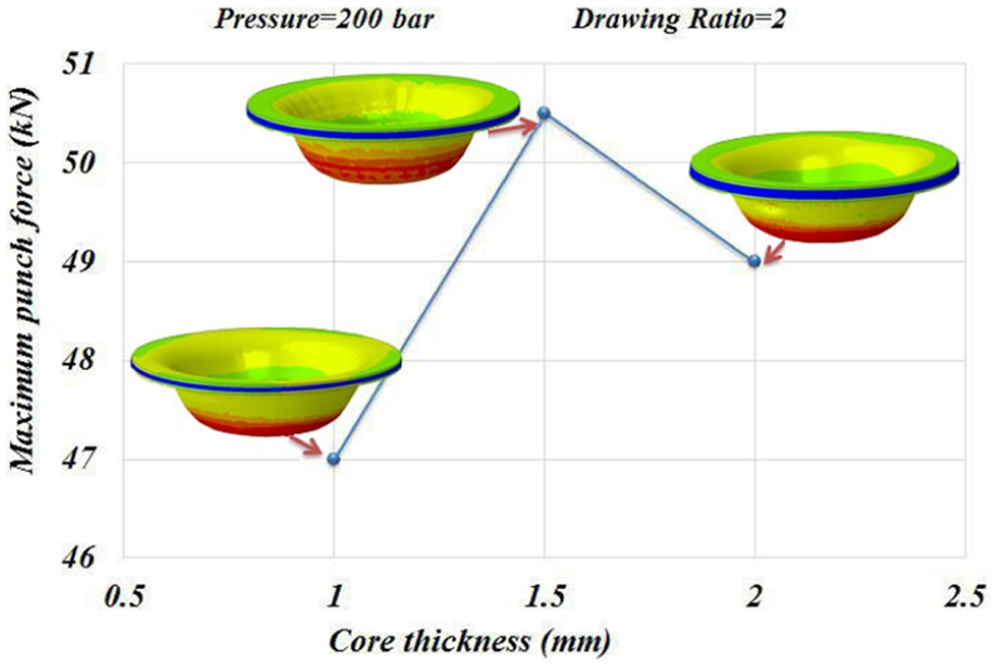
Effect of polymeric core thickness on the maximum punch force values for 316L/PP/316L sandwich sheet; thickness of a cover sheet: ts = 0.5 mm.
Comparison of the strain obtained from finite element simulation and experimental measurements
Circle grid analysis (CGA) method has been used to measure experimental strains. In this method, the blank is prepared by etching or painting a grid of circles on the surface of the initial blank. Plastic deformation makes the circles to become elliptical during the forming process. The amount of plastic strain can be observed in each circle and its size can be calculated by measuring the small and large elliptical diameters. A grid sample and a grid-etched three-layer sandwich sheet are shown in Figure 19.
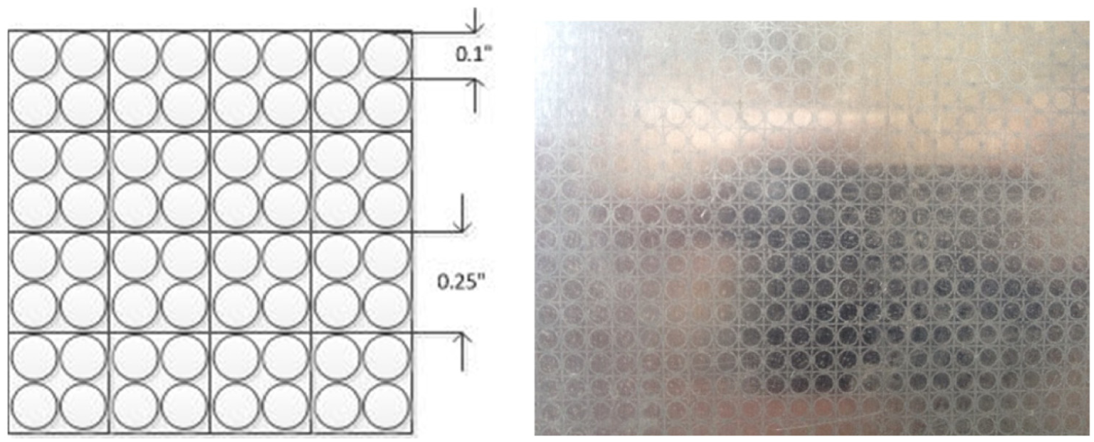
(Left) CGA pattern and (right) grid-etched blank sample.
A drawn sandwich sheet with a drawing ratio of 2 and constant pressure of 250 bar was considered for strain investigation. The radial and circumferential strains were measured after drawing the cup. These strains were also obtained from numerical simulation. Figure 20 compares radial strain obtained from the results of finite element and experimental measurements. As can be seen, there is a good agreement in results. The experimental measurement results report more radial strain. The average error of results of finite element simulation is almost 6%. The most value of radial strain is at the top of the wall and close to the flange area because in HMDD the oil pressure determines the die radius and causes more stretching in this area.
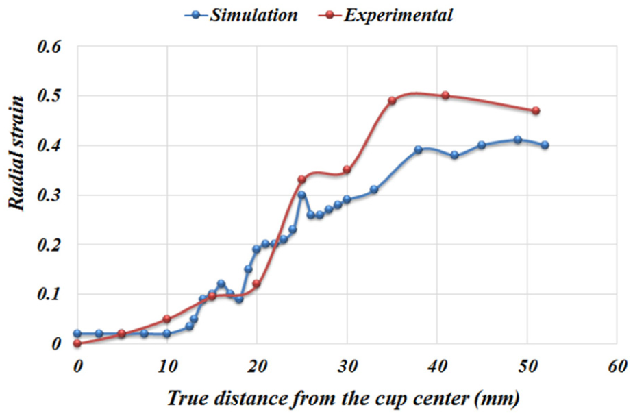
Comparison of the finite element simulation results and experimental measurements for radial strain of sandwich sample with drawing ratio of 2 and constant pressure of 250 bar.
Figure 21 compares the results of finite element and experimental measurements of circumferential strain in the sandwich sheet. The finite element results are relatively closer to the experimental measurement. Average error of the curve obtained through finite element simulation is about 3%.
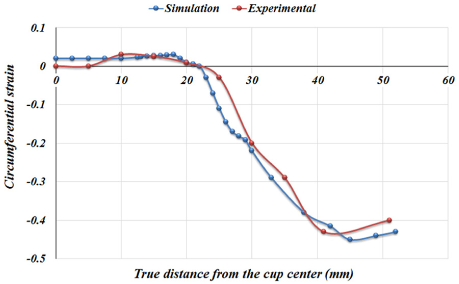
Comparison of the finite element simulation results and experimental measurements for circumferential strain of sandwich sample with drawing ratio of 2 and constant pressure of 250 bar.
Conclusion
In this research, process parameters such as the formability, drawing ratio, required force, strain achieved and critical pressure of a steel/polymer/steel sandwich sheet during HMDD process were investigated. For this study, experimental, theoretical and numerical routes were selected. Critical pressure curves and upper limit of safe zone were predicted by theoretical approach. A good agreement in simulation and experimental results was observed. And it stands to reason that finite element simulation is capable of predicting the rupture in this process. In summary, the following results could be obtained:
For the safe zone of fluid pressure, a good agreement was observed between simulation results and experimental measurements. It was observed that LDR is increased from 1.9 to 2.1 by increasing pressure from 0 to about 150 bar. But after 150 bar, LDR is decreased with the increase in pressure. So there is an optimum pressure of about 150 bar for HMDD process of 316L/PP/316L sandwich sheets.
LDR was increased about 15% in HMDD process compared to the conventional deep drawing. And this indicates an increase in formability of these sheets in HMDD process.
Increasing fluid pressure and drawing ratio causes significant increase in forming force. The average deviation in prediction of forming force by FEM is 12%.
The simulation results for predicting the strains show good agreement with experimental measurements. The average deviation for prediction of radial strains is 6% and for circumferential strains is 3%.
Finite element simulation results indicate that the interval of safe zone is narrowed by increasing the drawing ratio. Also the nose of curve of safe zone indicates LDR for sandwich sheets.
The results of theoretical analysis show that critical pressure is decreased by increasing the drawing ratio. Also the theoretical analysis results indicate an upper limit for predicting the safe zone of HMDD of sandwich sheets.
BHF is increased by pressure increasing. And consequently, the possibility of wrinkling is decreased.
Forming force is increased by increasing the core thickness from 1 to 1.5 mm. But increasing the core thickness from 1.5 to 2 mm decreases the forming force.
Footnotes
Appendix 1
Appendix 2
Appendix 3
Declaration of conflicting interests
The author(s) declared no potential conflicts of interest with respect to the research, authorship and/or publication of this article.
Funding
The author(s) received no financial support for the research, authorship and/or publication of this article.