
Abstract
Industry 4.0 is the need of the hour in current global market scenario and all the processes are moving toward automation and smart manufacturing. In machining, smart techniques implementation depends on developing a database for decision-making, which is the case for stack drilling in aerospace industry. In this application, choosing one optimal condition for several materials is a challenge due to their different machinability. Hence, material identification techniques are suitable approaches for adapting the cutting parameters in real time, which improves tool life, hole quality, and productivity. In that regard, the goal of the present paper is to create a specific force data map for axial drilling and circular milling processes based on its experimental force and power measurements. To do that, experiments were separately carried out on Titanium and Aluminum workpieces in a range of cutting speed and feed conditions. The results show that specific cutting and feed forces for each material can be identified on distinct regions of the map, without thresholds overlapping. Given that, these maps can be used as a signature to distinguish two metallic materials in real time machining. In this case, the specific data points at the interface layers may offer advantage to accurately identify tool position unlike monitoring gradient of feed forces while drilling stacked materials. Therefore, smart machining techniques seeking cutting parameters optimization can be implemented for a particular material.
Keywords
Introduction
Multi stack drilling is one of the major operations in aircraft assemblies and it demands lots of time and resources to achieve high-quality holes. Usually, Titanium and Aluminum stacked materials are drilled before aircraft assembly and this poses a major challenge in machining due to the different materials’ machinability. Some of the drilling challenges include poor finishing, burr formation, and rapid tool wear. 1 These hole quality aspects, as exit burrs, can have a significant influence during assembly and affect productivity. 2 Hence, as thousands of holes have to be drilled for assembling an airplane, techniques considering different materials’ machinability in a stack are crucial for performance maximization.
In this aspect, smart machining is a solution that refers to real time adaptation of cutting parameters for process optimization based in massive data from smart factories, specially using machine tool acquisition. 3 Previous research have presented prediction models and data monitoring techniques which can be helpful in smart machining applications. Wenkler et al. 4 developed a way of predicting specific cutting force by Artificial Neutral Network which can be implemented in process planning or smart manufacturing. Hegab et al. 5 predicts tool wear by using Machine Learning models for a wide range of cutting conditions in drilling. Furthermore, a smart machining system is developed by monitoring spindle power and torque in order to optimize feed rates in milling by Park et al. 6
One interest of applying smart machining during stack drilling is material identification. With this purpose, tool position detection inside the stacked layers is a key parameter so it is possible to adapt cutting parameters and machining strategies. Regarding this aspect, Pardo et al. 7 used cutting forces signals as input for three different decision-making algorithms to identify the tool position in stacked materials. Their objective was to compare the effectiveness of different approaches, which could be used for material identification. Jallageas et al. 8 developed a methodology for material identification in drilling multi-stacked material using thrust force signals. Their strategy used both: thresholds and gradient of forces to differentiate metallic materials and spectral analysis in order to distinguish aluminum and carbon fiber. The approach does not use any input process parameter, it uses pattern recognition for a specific drilling case. Material identification in stack drilling for a wide range of parameters is still a challenge that requires more research and the development. However, implementation of smart machining strategies in drilling alone may not completely optimize the process, so additionally other alternatives such as helical milling, also known as orbital drilling, can be applied.
Orbital drilling shows advantages regarding the process flexibility and ability to produce high-quality holes on different materials.9,10 Sun et al. 11 data shows that the fatigue life of holes produced by helical milling showed better life compared to conventional drilling. Although, cutting mechanistic is more complex in this process and so is the cutting models. Wu et al. 12 discussed force models for circular milling taking into account the uncut chip thickness and feed rates variation at the corners. The cutting coefficients calculation in circular model can be further extended for helical milling adding vertical feed.
In both hole making processes of aerospace materials: axial drilling and helical milling, the specific cutting coefficients data can be used to identify the material being machined. They can act as material signatures to adapt proper cutting parameters in real time. These data could directly improve the process productivity and hole quality if appropriate cutting parameters are applied for the specific material.
Hence, the goal of this paper is to develop a data map of specific force coefficients related to each material for both process: axial drilling and circular milling processes, not developed in the previous papers, for further application in helical milling. The materials used for the experiments were aluminum 2017A and titanium Ti6Al4V, being subjected to a common set of cutting conditions. In the following sections, the force model and cutting coefficients are presented, as well the experimental set-up. The cutting forces and power results are presented and discussed, and lastly, the identification map with cutting coefficients for both processes is built.
Force model and specific force coefficients
Mechanistic force models can provide quantitative cutting force predictions based on the uncut chip thickness principle. Once experimental tests are made, the cutting force models enable estimating the specific cutting coefficients for a different set of variables, as describe by numerous papers.13,14
The forces for a general orthogonal cutting can be described by a mechanistic force model considering only cutting action of the cutting edge neglecting plowing and chisel edge effects. The machining force
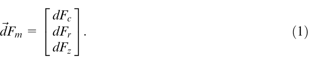
The local force in point P of the cutting edge is a function of the uncut chip thickness


where
For each rotating tool machining process there are some assumptions in order to identify a global value for specific forces coefficient: in drilling, milling, and circular milling, as follows.
Drilling
In drilling, local specific force coefficients can change along the cutting edge, as cutting speed varies from zero to the maximum cutting speed
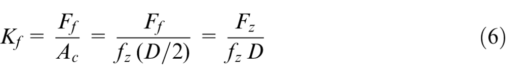
In drilling, it is not possible to experimentally measure the cutting force for a single cutting edge

On other hand, it is possible to measure the feed force
Milling
In milling, in order to determine the cutting coefficients of the tool-workpiece pair, the local cutting force
When summing the contributions of each cutting part
As in drilling, some assumptions should be made for the identification of specific cutting force and specific radial force. It is considered that the maximum force is achieved in the position of
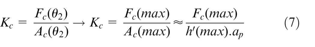
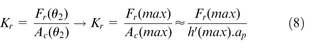
Considering that the measurement is taken using a fixed dynamometer, the acquisition is done in a
Circular milling
Unlike in linear milling, circular milling involves movement of tool around a centered fixed point in clockwise or anticlockwise direction to enlarge a existing hole diameter. Figure 1(b) shows the circular milling tool trajectory (at
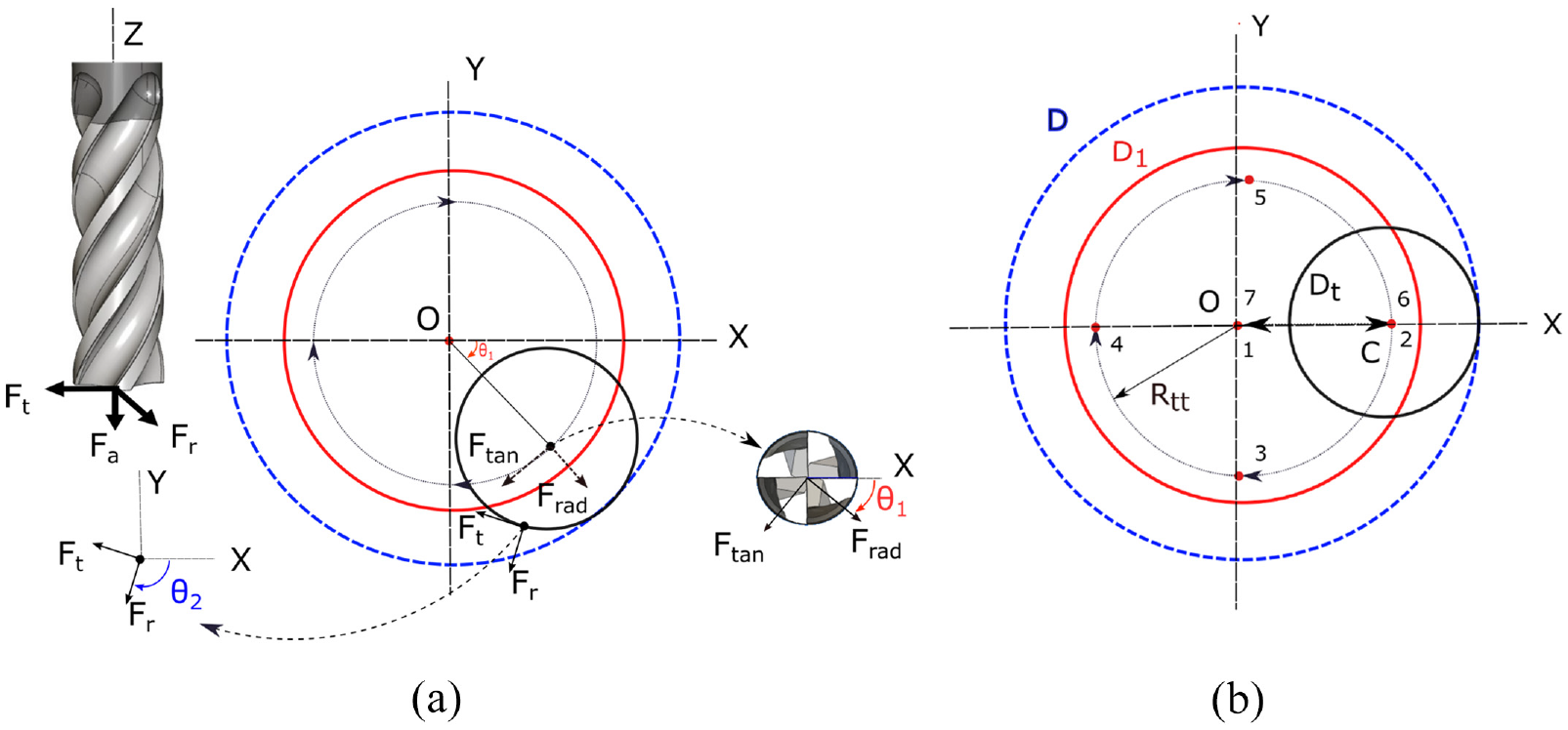
Referential frames in X and Y indicating cutting forces and tool trajectory in circular milling: (a) cutting forces and (b) tool trajectory (at
In circular milling, cutting forces at the cutting edge have different referential frames that have to be analyzed in order to determine the cutting coefficients of the tool-workpiece pair. The cutting forces exerted by the tool on the workpiece can be seen in Figure 1(a). Feed motion produces
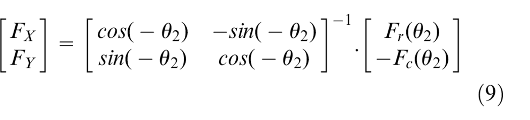
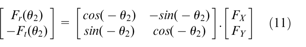
The forces measured during experiments by the dynamometer are in XY referential frame:

Materials and methods
In this section, drilling and circular milling experiments are presented in Aluminum (2017A) alloy and Titanium (Ti6Al4V) alloy workpieces measuring cutting forces and cutting power. The experiments were carried out for a specific range of cutting conditions, following the experimental setup and the design of experiments described below.
Experimental setup
All drilling and milling experiments were carried out on a CNC milling center DMU85-DMG mono block machine. Flood water-based through coolant was used for drilling and circular milling was carried out in dry condition. The tools used for the experiments were: carbide drills from Klenk having diameter 11
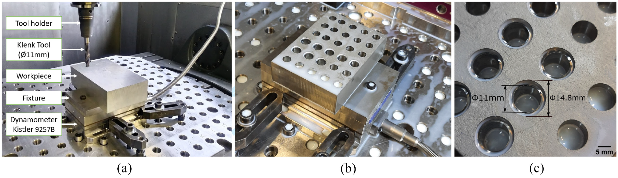
Experimental setup: (a) experimental elements, (b) workpiece (Titanium), and (c) milled dimensions (Titanium).
Analogical data of force and power were converted to digital using a 9201 National Instruments acquisition module with 10 kHz acquisition rate. The measured forces were filtered using a low pass Butterworth filter with cutoff frequency of 700 Hz (appropriated to the maximum spindle speed).
Design of experiments
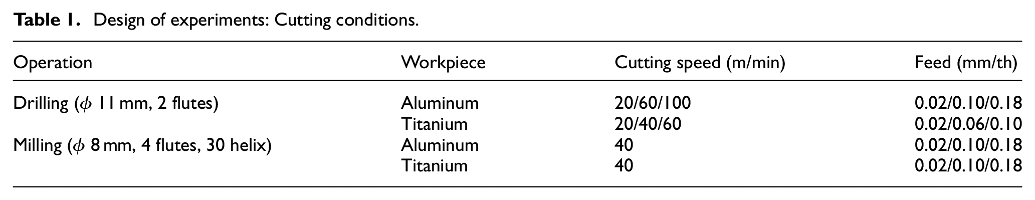
Table 1 summarizes the cutting conditions on Aluminum and Titanium along with tool details for drilling and circular milling operations. The range of cutting parameters is wider than usual because the goal was to compare the machining responses in both materials and processes for a wide range of cutting conditions. The lowest feed per tooth allowed for a monoblock carbide tool is included (
Design of experiments: Cutting conditions.
Experimental results
The following subsections present the results of feed force and power for drilling along with cutting forces for circular milling. The graphs are presented in terms of length of the hole for drilling for various cutting speeds and feed rates. Circular milling forces are presented in terms of tool angular position
Feed force and power in drilling
Regarding the cutting force, Figure 3 shows the results obtained per depth of the hole for Aluminum and Titanium respectively. Each figure contains results of different cutting speeds obtained at
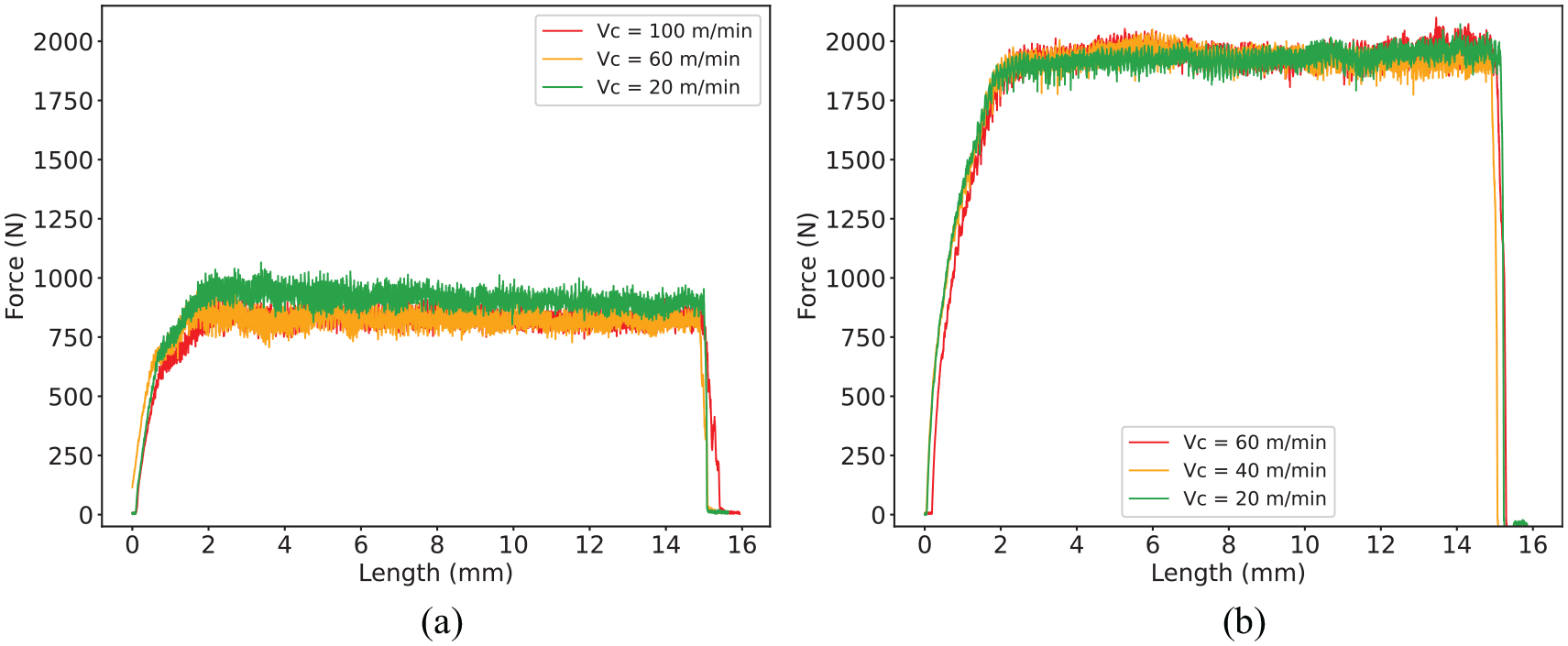
Experimental feed force for drilling Aluminum and Titanium: (a)
Cutting power results are shown in Figure 4 for Aluminum and Titanium at
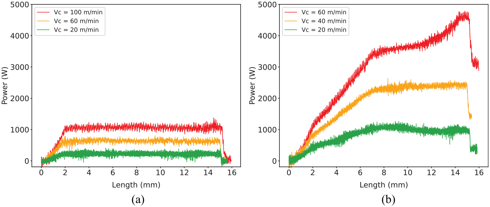
Experimental cutting power for drilling Aluminum and Titanium: (a)
Forces in circular milling
The cutting forces
Experimental forces
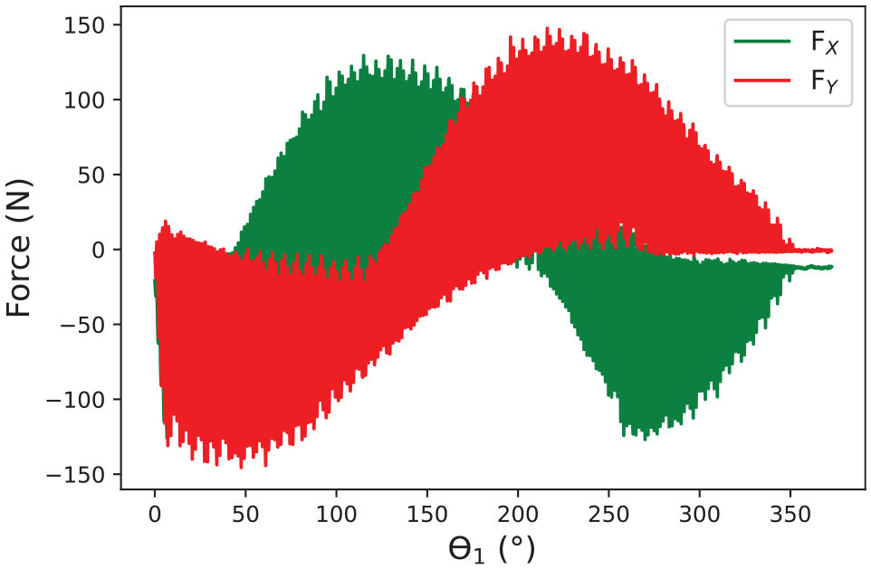
Figure 6 shows the variation of transformed forces at the cutting edge (
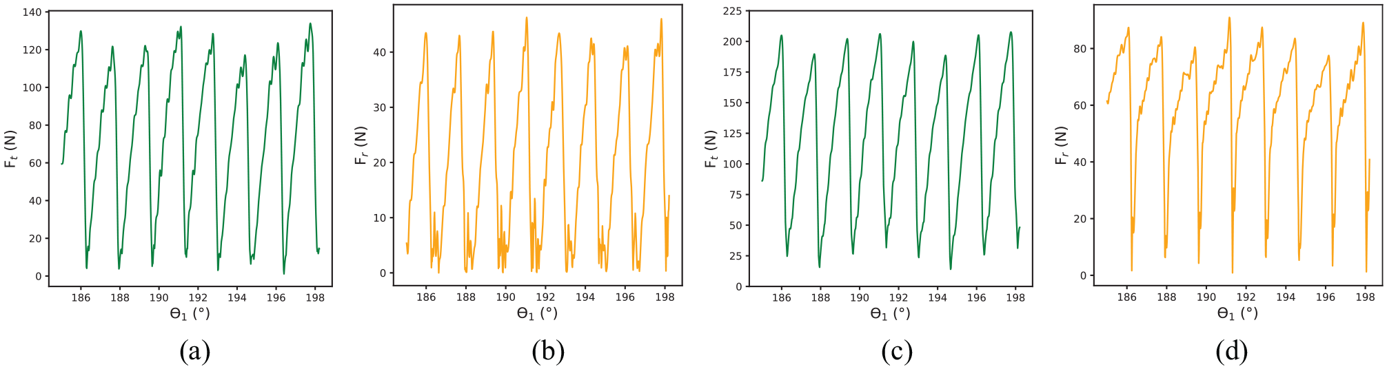
Calculated
Experimental specific force coefficients
After acquiring forces and power data for the analyzed processes, the specific cutting force coefficients were estimated. They are presented in the following subsections for the drilling and milling operations, followed by the targeted identification map. It is important to claim that the circular milling experiments were done after the analysis of drilling experiments. As the aim of this paper is the material identification based on the data, the range of feed per tooth was narrowed to 0.10 and 0.18 mm/th, where the values of forces were closer. Also, low feed rate values as 0.02 mm/tooth are very rarely used in the industry for these materials.
Specific force coefficients in drilling
The
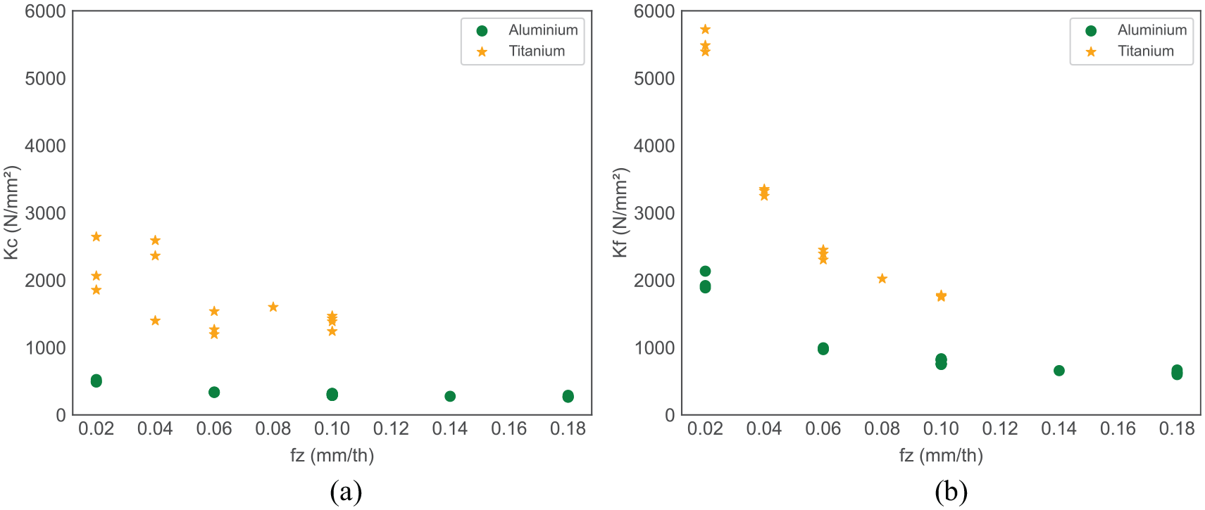
Specific force coefficients (
Specific force coefficients in circular milling
Figure 8(a) and (b) shows
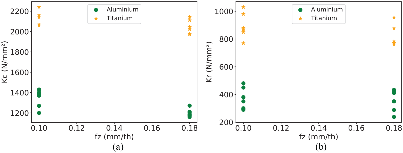
Specific force coefficients (
The data includes values calculated at several tool angle positions
It can be noted in Figure 8 that the specific coefficient values for Titanium are considerably higher compared to Aluminum, as observed for drilling.
Identification map
In this article we propose a clear distinction between both materials and force coefficient values identified in a single graphic, so called identification map. Even though the analysis of force coefficients per feed shows distinct results for different materials, identification can be mistaken through these results. This is because of the possibility of having similar coefficient values for both the materials at different feed rates.
Figure 9(a) and (b) presents the identification map using
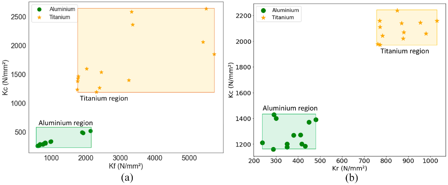
Identification map for drilling and circular milling in Aluminum and Titanium: (a)
In extreme situations, the acquired machining data can be incorporated to the commercial software in to alarm or stop the tool rotation in extreme situations, as it is already the case of power. 19
Conclusions
The main focus of this article was to demonstrate the possibility of material identification during hole making operations of two different materials by analyzing specific force coefficients. In this regard, cutting force and power data were analyzed to identify specific force coefficients for Titanium and Aluminum. Our work proposes utilization of data points of specific force coefficients for material identification while drilling stacked materials. This novel technique can help to adapt proper cutting parameters in real time. Such data maps with precise points of specific force coefficients can have advantages over monitoring of thrust forces for gradient change to identify materials or tool position in the stack.
The results can be summarized as follows:
In both operations, specific force coefficients are identified in different regions of the map for Titanium and Aluminum due to the materials distinct machinability;
During initial phase of axial drilling, when only chisel point is inside the material, the signals are similar comparing both materials and difficult to identify;
Considering drilling results in Titanium, the elastic recovery of material leads to an increase in power when the tool penetrates the workpiece. This elastic recovery disturbs the identification, it could lead to wrong interpretation of increasing specific cutting force inside the hole, which is not the case.
In circular milling, the transformed feed forces (
The variation of
Hence, the gap between the cutting force coefficients for both materials makes it suitable for applying smart machining techniques using data monitoring in hole making processes of stacked materials made out of Aluminum and Titanium.
Thus, as shown in this work, the specific force coefficients makes it possible to clearly identify different materials in real time, which is calculated by online monitoring of cutting forces and power. The calculation of instantaneous specific force coefficients for material identification and real time decision making to adapt cutting parameters will optimize the hole making process.
Footnotes
Declaration of conflicting interests
The author(s) declared no potential conflicts of interest with respect to the research, authorship, and/or publication of this article.
Funding
The author(s) received no financial support for the research, authorship, and/or publication of this article.