
Abstract
The profile with rectangular ribbed (日-shaped) section is applied to the anti-collision beam of commercial vehicles, which not only improves the anti-collision performance but also improves the lightweight of the car. With the gradual decrease of the bending radius of the profile, the profile is prone to defects such as wrinkling of the inner wall or fracture of the outer wall. In this paper, the ABAQUS, a finite element simulation software, is used to establish the simulation model of the profile with rectangular ribbed section during the process of rotary draw bending, and the stress and strain laws are analyzed. The bending forming limit of the profile with rectangular ribbed section is studied by choosing the fracture of the outer wall as the evaluation standard. And the influences of bending speed, friction coefficient, and thickness on the forming limit are obtained. The minimum bending radius decreases as the bending speed increases and increases with increasing of friction coefficient and thickness.
Introduction
Rotary draw bending refers to the forming method in which the blank metal is rotated and gradually bent around the forming die under the action of external force.1–3 The process has many advantages such as uniform deformation, good surface quality, and convenient mechanized production so that it is commonly used in automotive and aerospace fields.4–6 In this paper, the rotary draw bending was used to form the rectangular ribbed (日-shaped) section anti-collision beam.
The rectangular ribbed section anti-collision beam using high-strength steel is a thin-walled pipe fitting structure, which has the advantages of lightweight and high rigidity. 7 When a car crash occurs, the anti-collision beam will produce a series of complex deformations to absorb the collision energy. Thereby the anti-collision performance of the car is significantly improved. However, due to the characteristics of high strength and poor plasticity of high-strength steel, the current production of rectangular ribbed section anti-collision beam faces many problems. Based on the needs of production, our team has conducted sufficient researches on the rectangular ribbed section anti-collision beam. Figure 1 is a diagram of the bending device for the profile with rectangular ribbed section and Figure 2 is a product diagram after bending. Liang et al. used the COPRA software to design the rollers and the ABAQUS software to simulate the forming process and studied the edge buckling defects in the one-time rolling process of forming the profile with rectangular ribbed section. It was found that the edge buckling decreased with the increase of the plate thickness and the edge buckling increased as the height of the flange increased. 8 Liang et al. established a finite element simulation model of the profile with rectangular ribbed section through the ABAQUS software and simulated the bending process using rigid and plastic mold cores. The results showed that the rigid mold core is more conducive to the reduction of wrinkles. 9 Liang et al. studied the rotary drawing bending process of profile with rectangular ribbed section and based on the analysis of the bending mechanism, designed a new flexible core mold with a self-locking device, which effectively improved the forming quality. 10
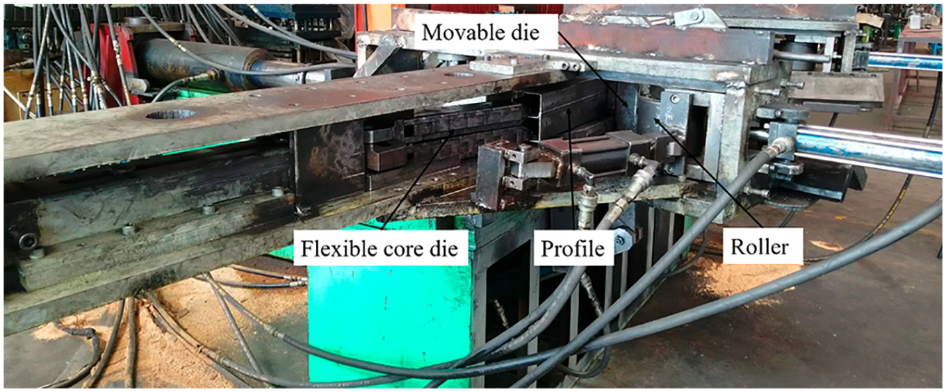
Diagram of the bending device for the profile with rectangular ribbed (日-shaped) section.
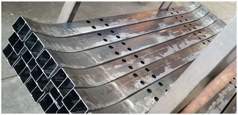
Diagram of product.
Generally speaking, the plastic forming limit can be characterized by the maximum amount of deformation that occurs before plastic deformation instability. For rotary draw bending, the forming limit is the minimum bending radius that can be achieved without forming defects that affect the application.11,12 The following evaluation criteria are generally used when researchers study the bending forming limit of profiles. The material in the outer side of strain neutral layer of bending is not excessively stretched to cause fracture and the material in the inner side of strain neutral layer of bending is not excessively compressed to cause wrinkling. When the forming accuracy is higher, the section distortion should be considered.13–15 Wei et al. studied the influence of process parameters on the forming limit of free bending pipes. The results showed that the axial advancing speed and the gap between the tube and dies have greater influences on the forming limit, and the relevant parameters corresponding to the minimum bending radius were determined. The research also found that the yield strength was an important factor affecting the forming limit. 16 Liu et al. studied the minimum bending radius of Al-Li alloy during stretch bending process by numerical calculation, finite element simulation and experiment verification. And three types of failures for fracture limit of Al-Li alloy were put forward. 17 Xiao et al. studied the bending forming limit of H96 brass tube with double-ridged rectangular based on the section distortion. Through methods of virtual orthogonal experiment design and finite element simulation, three-dimensional forming limit diagrams under different processing conditions were obtained. 18 Zhao et al. studied the inner wrinkling during the rotary draw bending process of a thin-walled rectangular tube, proposed a wrinkle wave function, and established a wrinkle prediction model. It was proved that with the increase of the ratio of thickness to width and the ratio of thickness to height, the minimum bending radius of the tube gradually became smaller. 19
At present, the research on the profile with rectangular ribbed section is still in the study of the anti-collision beam for commercial vehicles. However, no one has studied the bending limit of the profile with rectangular ribbed section. Since the flexible mold core can effectively reduce the wrinkling and cross-sectional distortion of the inner wall during the bending process, the main problem in the production of an anti-collision beam is the fracture of the outer wall. In this paper, the bending limit of the profile with rectangular ribbed section is studied by using the ABAQUS software combined with the JOHNSON-COOK plastic model and damage criterion. And the fracture of the material in the outer wall is chosen as the evaluation criterion for the forming limit.
Establishment of the finite element simulation model of rotary draw bending
Establishment of model of parts
The required component models are established in the Part module of the ABAQUS and are assembled into an assembly in the Assembly module. The schematic diagram and cross-sectional dimensions of the profile with rectangular ribbed section are shown in Figure 3. Due to the complexity of the welding seam, the profile is idealized and is connected by the order of Tie constrain.
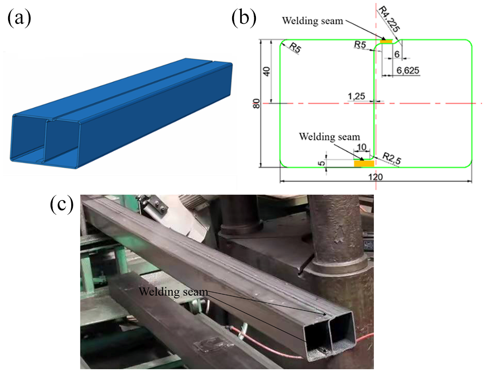
(a) Diagram of the profile, (b) dimension drawing of cross-section, and (c) photo of profile.
Since there are so many parts involved in the movement of the rectangular ribbed section profile during the rotary draw bending process, which can be seen in Figure 1, the model is simplified based on the requirements of simulation calculation. The profile is restricted by multiple molds such as the bending die, movable die and core die during the forming process. In the simulation, the radius of the bending section of the bending die is 180 mm and the length of the rectangular section for fixing the profile is 700 mm. The core die should completely include the profile deformation section, plus the head and tail of the core die, with a length of 558 mm. The radius of the roll is 60 mm and the height is 120 mm and the length of the movable die is 455 mm. The schematic diagram of the molds and assembly are shown in Figure 4.
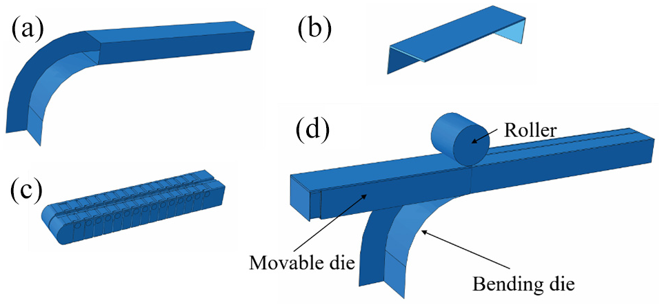
(a) Bending die, (b) movable die, (c) flexible core die, and (d) assembly drawing.
During the bending process, the movable die performs bending movement under the action of the hydraulic roller, which drives the profile to bend and fit the bending die. So, the surface-to-surface contact is used to define the interaction between the surface of movable die and the surface of roller and the coefficient of friction is controlled in this paper. In addition, a general contact is used to define the interaction of other contacting surfaces and the friction coefficient is set as 0.15.
Material properties and mesh
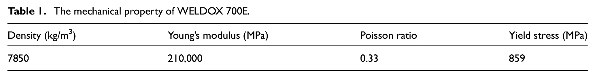
It is required to specify the material and section properties of the parts in the Property module of the ABAQUS and the values of stress and strain in the software should be the values of true stress and true strain. In this paper, the molds are modeled by discrete rigid body and the profile is modeled by 3D deformable shell. The thickness of the shell is set as 2.5 mm, the Simpson thickness integration rule is chosen and the thickness integration point is set as 5. It is not necessary to define material properties for rigid molds. The material of the profile with rectangular ribbed (日-shaped) section is WELDOX 700E, which is a low-alloy high-strength steel with good weldability. The grain size of WELDOX 700E is small, the comprehensive mechanical properties are good and the high-speed impact resistance is excellent in particular. The mechanical property of WELDOX 700E are listed in the Table 1. 20
The mechanical property of WELDOX 700E.
In the ABAQUS software, if you want to show the fracture effect in the Visualization module, you must add a damage model to the material properties in the Property module and select corresponding output command in the Step module. The Johnson-Cook model has been widely used in the problems of impact on metal structures and nonlinear large deformation due to its simple form, clear physical meaning and relatively easy access to parameters. The equation of Johnson-Cook constitutive model is as follows21,22:
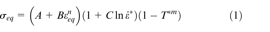
Where, A, B, and n are the yield strength, strain hardening coefficient and strain hardening index of the material at the reference strain rate and reference temperature respectively; C is the strain rate sensitivity coefficient; m is the temperature softening index;
Based on the cumulative damage criterion, the Johnson-Cook fracture criterion considers the effects of stress triaxiality, strain rate and temperature. And its expression is as follows:
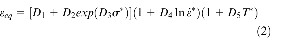
Where, D1, D2, D3 are influence parameters of the stress triaxiality; D4 is the strain rate sensitivity coefficient; D5 is the temperature sensitivity coefficient;
The damage evolution of unit is defined as:
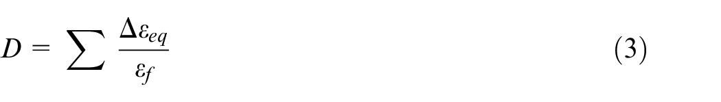
Where, D is the variable of damage,
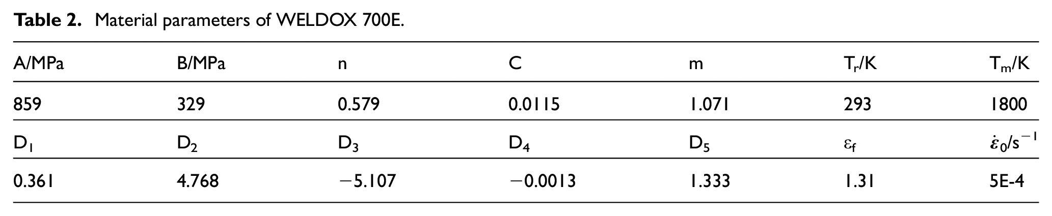
In this paper, the Johnson-Cook plastic model and Johnson-Cook fracture criterion are used in the ABAQUS software. The major material parameters are shown in Table 2.20,23
Material parameters of WELDOX 700E.
The part models are meshed respectively in the Mesh module of ABAQUS. A four-node curved surface shell reduced integral unit (S4R) is used to mesh the profile with rectangular ribbed section cross-section profile and an eight-node linear hexahedral reduced integral unit (C3D8R) and A 4-node bilinear rigid quadrilateral unit (R3D4) are used to mesh the forming dies. In the bending process, only the profile participates in the plastic deformation, so the global size of profile unit is set a smaller value which is 5 mm. And the unit size is 10 mm for the bending die and 7 mm for the other dies. The meshing result is shown in Figure 5.
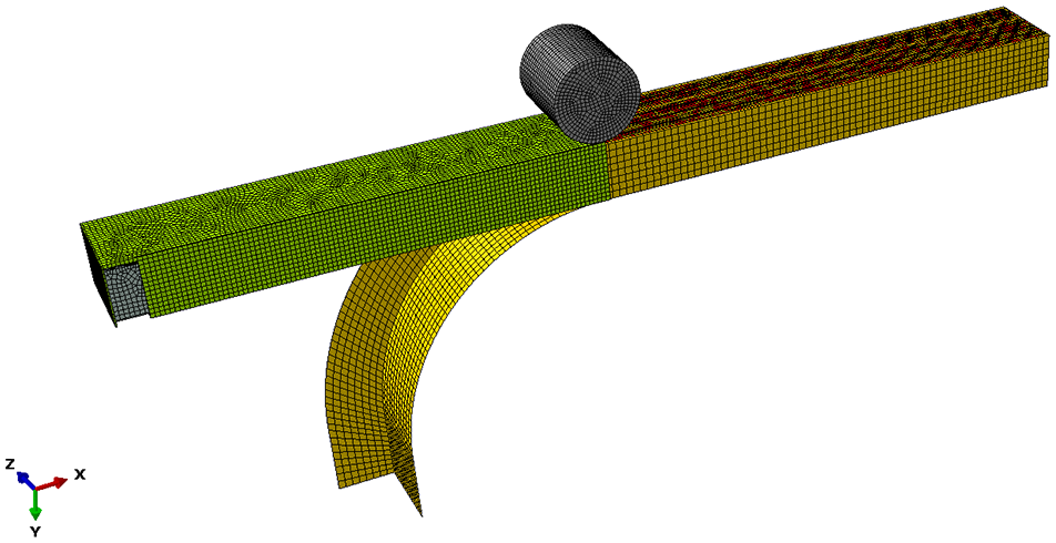
Diagram of mesh.
Steps and boundary conditions
The process of the creation of analysis steps and the settings of output data are completed in the Step module of ABAQUS. The dynamic explicit algorithm is chosen because the rotary draw bending is a complex nonlinear large deformation process. On the basis of the initial analysis step, the bending step under the dynamic explicit algorithm is added and the geometric nonlinearity parameter Nlgeom is set as On. On the basis that the calculation accuracy is not greatly affected, the step time of forming is set as 0.5 s and the mass scaling factor is set as 100 in order to shorten the calculation time and ensure the calculation efficiency. The results of stress, strain, displacement, etc. of the profile during the forming process are chosen as the field output variables. In particular, the Status option of the field output variable is checked in order to display the damage results.
The boundary conditions are defined in the Load module of ABAQUS. During the bending process, the roller rotates around the center of the bending die and the movable die also performs bending movement under the action of the roller, which drives the profile to bend and fit the bending die. As a result, the rotary draw bending process is completed as is shown in Figure 6. The movement around the bending roller is constrained through the “speed/angular velocity” command, and the angular velocity is set as π rad/s. For the flexible core die, the translations in the U3 direction and the rotation in the UR1 and UR2 directions should be restrained. For the bending die and the end of profile, fixed constraints should be added.
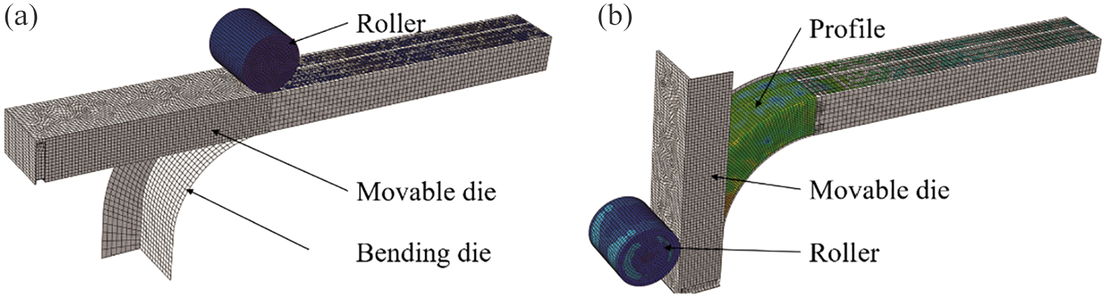
Position of molds (a) before bending and (b) after bending.
Analysis and verification of simulation results
Numerical simulation calculation of the rotary draw bending process of the profile with rectangular ribbed section is carried out by ABAQUS. And the Mises stress distribution of the calculation result, which is displayed by cloud diagram, is shown in Figure 7. It can be seen that the stress distribution in the bending forming zone and the forming zone are quite different. The stress in the bending forming zone is relatively large, while the stress in formed zone basically disappears because the restrictions of the forming dies are weakened.
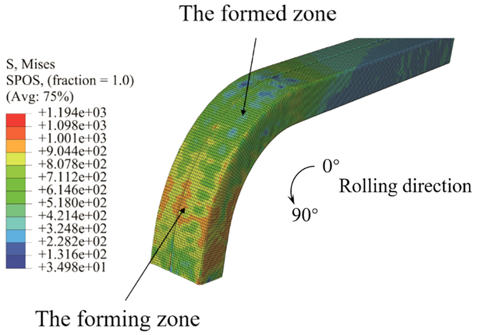
Diagram of Mises stress distribution.
Taking the center of the bottom surface of the bending die as the origin, the height direction of the profile as the radial direction, the length direction of the profile as the tangential direction, and the width direction of the profile as the axial direction, the cylindrical coordinate system is established as shown in Figure 8(a). Under the cylindrical coordinate, the tangential strains within the bending range of the inner wall centerline and the outer wall centerlines of the left and right cavities are extracted following the path which are shown in Figure 8(b). It can be seen from Figure 8(c) that the tangential strain of the inner wall of the profile is compressive strain. And as the bending angle increases, the compressive strain gradually increases, reaching an extreme value at bending angle of 70°, which indicated that the wrinkling is most likely to occur in the material of inner wall in this area. The tangential strain of the outer wall of the profile with rectangular ribbed section is tensile strain. And the strains of centerlines of the outer wall of the left cavity and the right cavity have a similar trend: with the increase of the bending angle, the tensile strain increases sharply, reaching the maximum at the bending angle of 10° and a “spike” is formed in this area after which the strain drops to a lower level. This shows that the material of outer wall in the area is the most prone to fracture. The “spike” of the right cavity is higher than that of the left cavity, indicating that the fracture is more likely to occur at the outer wall of the right cavity. Thus, the tangential strain of the outer wall of the right cavity will be analyzed in the following simulations.
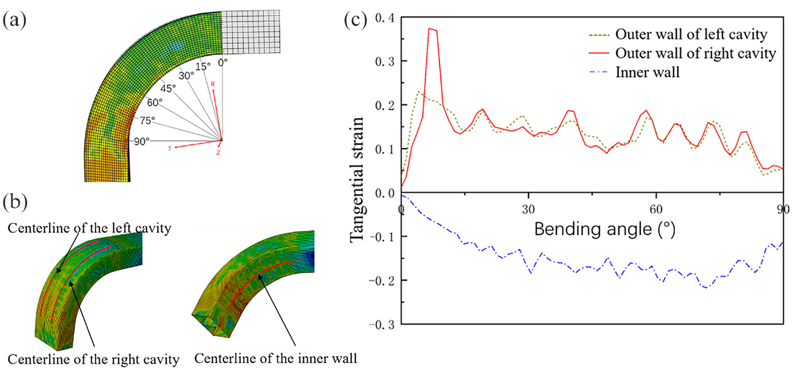
(a) The cylindrical coordinate system, (b) the node locations where the tangential strains are extracted, and (c) diagram of tangential strain.
The tangential strains of the outer wall of the right cavity under different bending radii are extracted by the same method. Figure 9 shows the tangential strains of profiles with radii of 190, 170, and 150 mm respectively and it can be seen from the figure that the bending radius has a vital influence on the tangential strain of the outer wall. As the bending radius decreases, the tangential strain of the outer wall gradually becomes larger. And the increase of tangential strain is most obvious in the “spike” area, which is at the bending angle of 10°. It can be inferred that when the bending radius reduces to a certain extent, the strain in the area will exceed the allowable forming limit of the material and as a result, the outer wall will break and cause the forming failure. Actually, as is shown in Figure 10, when the radius drops to 140 mm, the results of rotary draw bending, both simulation and test, have begun to fracture. It can be seen that the result of test is basically consistent with the simulation result and fractures of both situations occur at the area of the same bending angle, which also indicates that the finite element model can well predict the fracture of profile in the process of rotary draw bending. Therefore, the model can be used to study the influence of different parameters on the minimum bending radius.
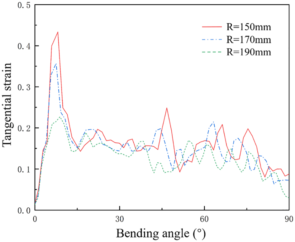
Tangential strain of the outer wall under different bending radii.
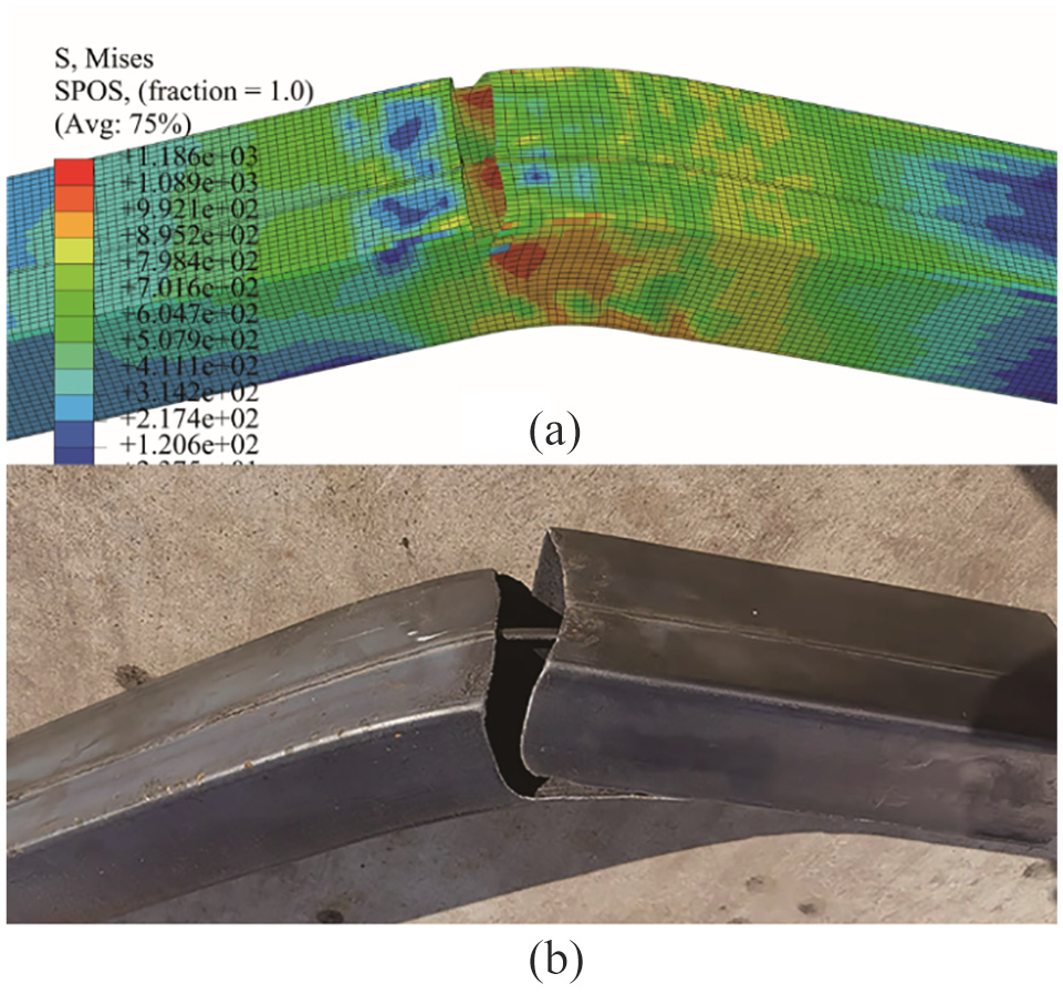
(a) Fracture in simulation result and (b) fracture in test.
Study on the bending forming limit of profile
The influence of bending speed on the bending forming limit
Regarding the rotary draw bending process of profile with rectangular ribbed section, the bending speed mentioned in this section refers specifically to the angular speed of the roller rotating around the bending die. In order to study the influence of bending speeds on the bending forming limit, the bending speeds in the forming process are set as v = 0.19, 0.22, 0.26, 0.31, 0.39, 0.52, 0.78, 1.57,and 3.14 rad/s respectively under the condition of ensuring that other factors are completely consistent. The results are analyzed and the tangential strains of the centerline on the outer wall of the right cavity at different bending speeds are extracted, which are shown in Figure 11. From the data in the figure, it can be seen that under different bending speeds, the tangential strain changes with the bending angle in similar trends. As the bending speed decreases, the “spike” at the bending angle of 10° increases suddenly. This is because the bending process in this paper is completed under cold deformation. With the bending speed decreasing, the flow speed of material decreases and the ability of uniform plastic deformation of the material also decreases gradually. At the same time, the smaller the bending speed, the longer the contact time between the profile and the movable die. As a result, the time that the die can stretch the material is longer and the value of strain is higher. When the bending speed drops to v = 0.19 rad/s, the tangential strain of the centerline on the outer wall is the largest and a platform appears at the extreme value, indicating that the outer wall has already cracked at this moment.
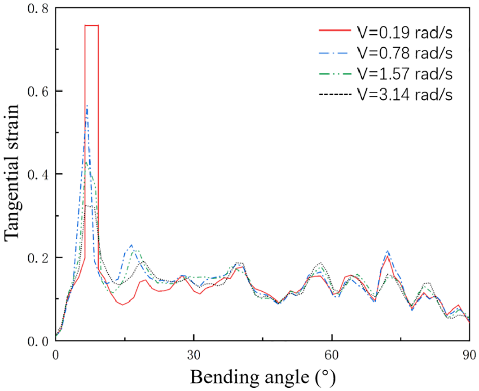
Tangential strain under different bending speeds.
Under different bending speeds, the bending radius of the bending model are gradually reduced until the fracture phenomenon takes place in the simulation results. The pictures that fracture just appears at different bending speeds are shown in Figure 12. It can be seen that the fractures all occur at the bending angle of 10°, which is consistent with the law that the tangential strain changes with the bending angle.
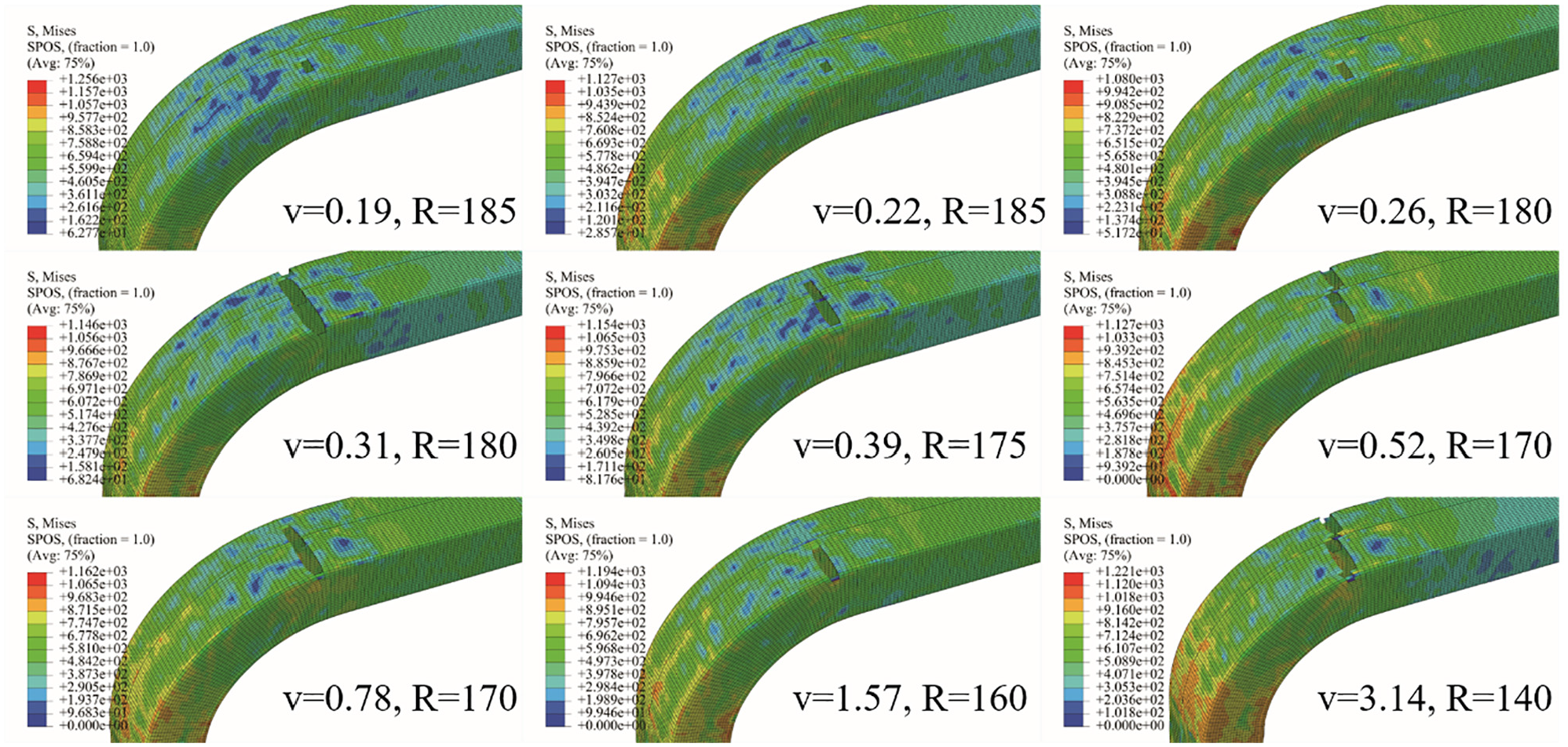
Initial fracture under different bending speeds.
Correspondingly, the influence of bending speed on the minimum bending radius is shown in Figure 13. The shaded area in the figure is the fracture zone and the blank area is the bending forming zone. The reason why there is a “platform” in the curve in the figure is that within this speed range, the variation of speed is not enough to cause a change in the minimum bending radius. Overall, as the bending speed increases, the minimum bending radius drops gradually. In order to verify the accuracy of the simulation, two points below the curve including a and b in the figure are extracted for experimental verification. Rotary draw bending tests for radius of 170 mm under bending speed of 1.0 rad/s and for radius of 150 mm under bending speed of 2.5 rad/s are conducted respectively and it is proved that both a and b undergo different degrees of fracture, which means the curve in Figure 13 is credible.
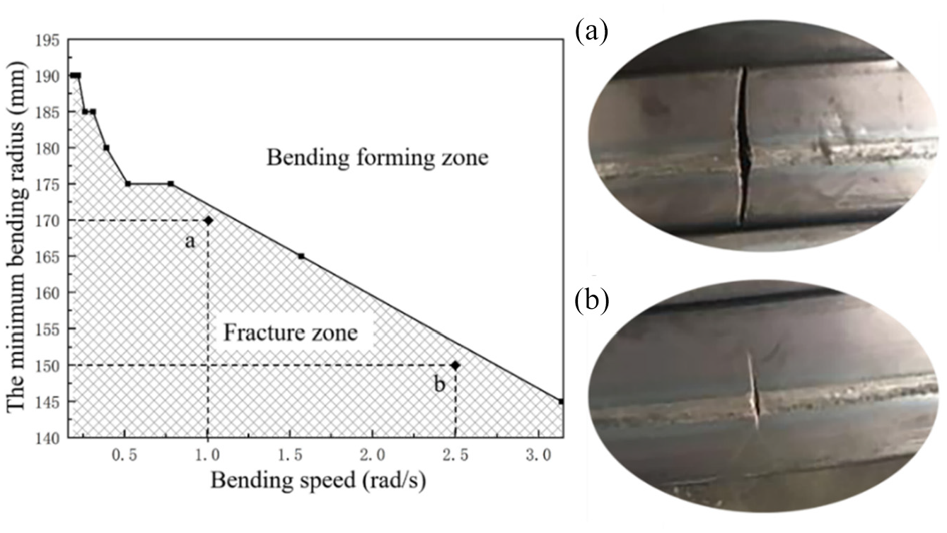
Influence of bending speed on the minimum bending radius: (a) the fracture result of point a; (b) the fracture result of point b.
Influence of friction conditions on bending forming limit
During the forming process, the outer wall of the profile will be in close contact with the movable die and the flexible core die and there will be a huge friction force. It is necessary to study the influence of friction conditions on the bending forming limit. When the consistency of other forming conditions is ensured, the simulations under different friction conditions can be realized by changing the friction coefficient of the general contact. In this paper, the simulations of rotary draw bending process under different friction coefficients (f = 0.10, 0.125, 0.15, 0.175, 0.20, 0.225, 0.25, 0.275, 0.30) are studied respectively. The results are discussed and the tangential strains of the centerline on the outer wall of the right cavity under different friction conditions are picked up, which are shown in Figure 14. It can be seen from the figure that under different friction conditions, the variations of tangential strain of outer wall with bending angle are basically equal. As the friction coefficient increases, the value of tangential strain at the peak increases significantly. That is, with the increasing of the friction coefficient, the material in outer wall is more prone to fracture. The reason is that as the coefficient of friction increases, the tangential tensile stress on the outer wall increases suddenly.
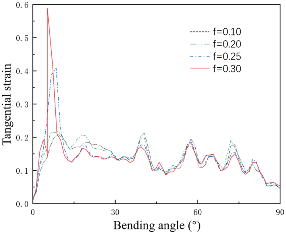
Tangential strain under different friction coefficients.
The bending radii are gradually reduced under different friction conditions until the fracture just appears in the simulation results. Figure 15 shows the cloud pictures when the fracture just arises under different friction conditions. It can be seen from the figure that the fracture phenomena all appear in the area at the bending angle of 10°, which coincides with the area where the strain peak appears.
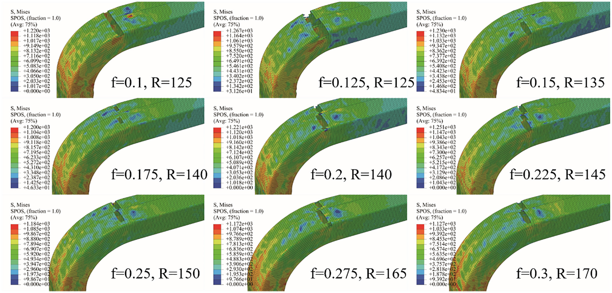
Initial fracture under different friction coefficients.
Figure 16 shows the influence of friction conditions on the minimum bending radius. The shaded area in the figure is the fracture area and the blank area is the bending forming area. It can be seen that as the friction coefficient increases, the minimum bending radius of profile increases. Also, bending tests under different friction conditions of two points below the curve are conducted. The liquid paraffin as lubricant is used for the bending test A and the boron nitride (BN) as lubricant for the bending test B. The results of fracture is shown in Figure 16 and it indicates that the curve is the limit curve of fracture.
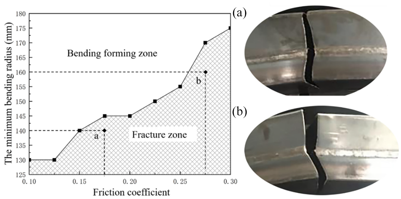
Influence of friction coefficient on the minimum bending radius: (a) the fracture result of point a; (b) the fracture result of point b.
Influence of thickness on bending forming limit
The rotary draw bending processes with thicknesses of t = 2.25, 2.5, 2.75, 3.0, 3.25, 3.5, 3.75, 4.0,and 4.25 mm are simulated respectively. The simulation results are analyzed and the tangential strains of the centerline on the outer wall of the profile with different thicknesses are extracted, which are shown in Figure 17. It can be seen from the curves in the figure that the variation tendencies of tangential strain under different thicknesses are similar: as the bending angle increases, the tangential strain has higher peaks in the area at the bending angle of 10°and 45°. And with the increasing of thickness of profile, the peak value of tangential strain also increases, which indicates that the possibility of fracture of the outer wall increases and that the material in the area at the bending angle of 45° increases the risk of fracture when profile is thicker. This is because as the thickness of the profile increases, the distance between the outer wall of the profile and the bending neutral layer will increase, resulting in an increase in the tangential strain of the outer wall.
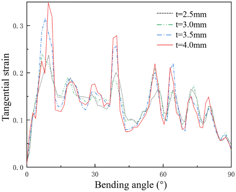
Tangential strain of different thickness.
Also, the bending radii of profiles with different thicknesses are gradually reduced until the simulation result just shows fracture. Figure 18 shows the cloud diagrams when the fracture phenomenon just occurs under different thicknesses and it can be seen that the fracture position is consistent with the position of strain peak.
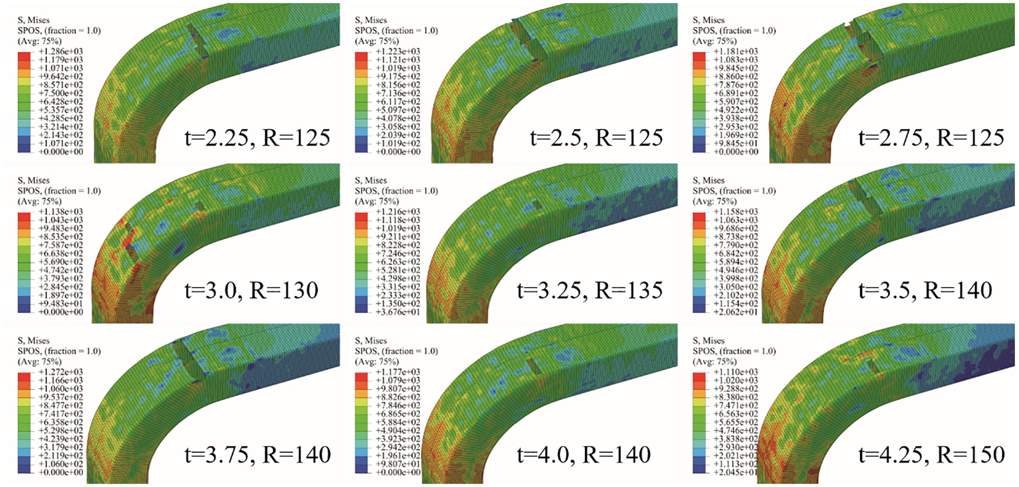
Initial fracture of profiles with different thicknesses.
Figure 19 shows the relationship between the minimum bending radius and the thickness of the profile. The shaded part in the figure is the fracture zone and the blank part is the bending forming zone. It can be seen from the figure that when the profile is relatively thin (t < 2.75 mm), increasing of thickness is not enough to cause a change in the minimum bending radius. However, the minimum bending radius increases as the thickness increases when the profile is thick (t > 2.75 mm). Then two points below the curve are chosen and bending tests are conducted respectively. The results shown in Figure 19 reveal that the fractures occur in both tests and the reliability of the critical curve is confirmed.
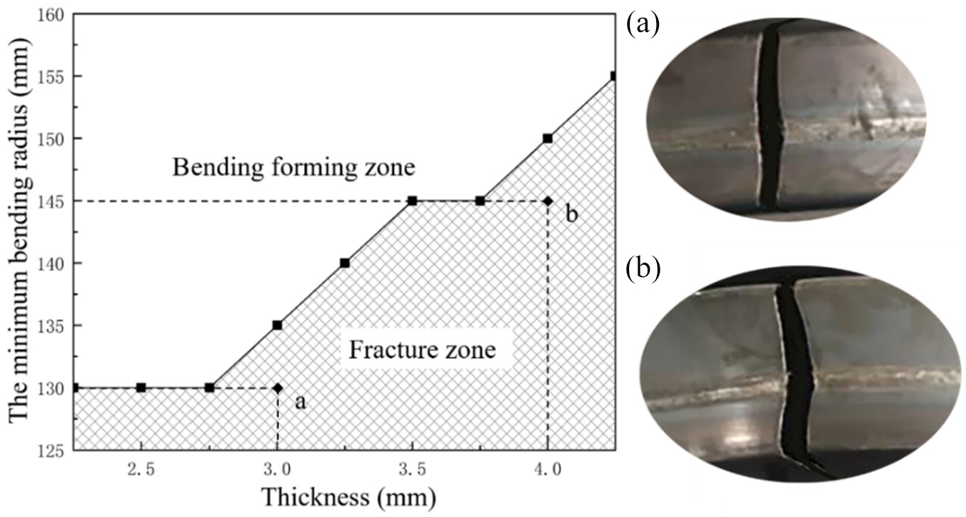
Influence of thickness on the minimum bending radius: (a) the fracture result of point a; (b) the fracture result of point b.
Conclusion
(1) A finite element simulation model of rotary draw bending process for the profile with rectangular ribbed section is established and the distributions of stress and strain of the profile are studied. And the influence law of the bending radius on the tangential strain is studied and it is proved that the tangential strain increases obviously with the decreasing of bending radius.
(2) The fracture of the material in outer wall is chosen as the evaluation criterion and the bending forming limit of the profile with rectangular ribbed section is studied. The influences of bending speed, friction coefficient, and thickness on the bending forming limit and the corresponding critical curves are obtained. The minimum bending radius decreases with the increase of bending speed, and increases with the increase of friction coefficient and thickness.
Footnotes
Author contributions
Ce Liang, Fulei Huang, and Jicai Liang developed the idea of the study; Fulei Huang, and Yi Li participated in its design and coordination and helped to draft the manuscript; Fulei Huang, and Yi Li contributed to the acquisition and interpretation of data; Ce Liang, and Jicai Liang provided critical review and substantially revised the manuscript. All authors read and approved the final manuscript.
Declaration of conflicting interests
The author(s) declared no potential conflicts of interest with respect to the research, authorship, and/or publication of this article.
Funding
The author(s) disclosed receipt of the following financial support for the research, authorship, and/or publication of this article: This work was financially supported by the China Postdoctoral Science Foundation (2017M611321).
Availability of data and material
The datasets used or analyzed during the current study are available from the corresponding author on reasonable request.