
Abstract
For the purpose that the multi-axis machine tools can machine workpieces flexibly and accurately, it is important to ensure that each axis of the machine tool can be linked with each other, and the geometric tolerances are within their required range. However, each tolerance is not only related to its own kinematic axis, but also affected by the comprehensive influence of other kinematic axes, which brings great difficulties to the modeling of geometric tolerances. This paper focus on developing a modeling methodology to describe the relationship between the range of machining geometric tolerance and the motional domain of machine tool axe based on an improved Jacobian-Torsor theory. General formulas for the expression of the geometric tolerances are derived. Experiments are carried out on five four-axis machine tools, type CNC-SH50, to verify the effectiveness of the proposed kinematic Jacobian-Torsor model in dealing with the interaction analysis of geometric tolerances.
Keywords
Introduction
Multi-axis machine tools are crucial in high precision and flexible machining. The mutual connection and tolerance control between multiple axes are the basis to ensure the high precision and flexibility machining properties of machine tools. Geometric error, thermal error and force error are the main error sources in machining process of machine tool.1–4 The geometric error is stable, repeatable, and measurable, 5 so it is the most economical and effective method to enhance the accuracy of machine tools by clarifying the error sources of geometric error and their transfer law. 6 The variation range of geometric error is defined as geometric tolerance. By expressing the tolerance range and influencing factors of geometric error of machine tool accurately, the tolerance range of geometric error can be reduced while improving the accuracy of machine tool.
Over the past decades, many researchers have done a great quantity of researches on the mechanism of generation and transmission of geometric errors of numerical control (NC) machine tools and made important contributions to the modeling and compensation of geometric errors. The homogeneous transformation matrix (HTM)7–10 based on the theory of rigid multi-body kinematics11–13 is used to establish the error transmission between cutter location and tool orientation. Multi-body system theory 14 based on the mathematical algorithm of the HTM broadens its application scenarios and convenience. In recent years, geometric error modeling theories for multi-axis machine tools have experienced a quick development. The stream of variation, 15 differential transformation,16,17 differential motion matrix, 18 and screw theory 19 have been presented and applied successively. These studies have made great contributions to the analysis of geometric errors of machine tools. However, in multi-axis machine tools, geometric error is not only related to its own kinematic axis, but also affected by the comprehensive influence of other kinematic axes, which were ignored by existing models.
When the machine tool moves along the tool path in the workspace, all error elements accounts for the deviation of the tool tip relative to the position and direction of the workpiece. For a single kinematic axis itself, only positioning error affects the deviation. Straightness error, angle tolerance and inter axis error do not affect its own motion accuracy but will affect the motion accuracy of other axes installed on the axis. As shown in Figure 1, the Y-axis is installed on the X-axis, and there is a perpendicularity error SXY between the X-axis and the Y-axis. The machine tool will produce an error of
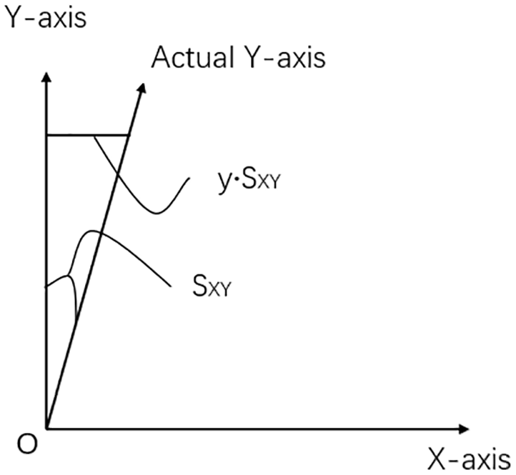
Influence of perpendicularity error SXY between X and Y axes on X-axis motion.
Consequently, it is necessary to analyze the relationship between the range of machine geometric tolerance and the relative kinematic space domain of different axes so as to describe the geometric tolerance when the machine tool is in a kinematic state. To achieve this goal, it is necessary to figure out how the geometric tolerance generate and transmit. And many tolerance analysis methods have been presented to solve this problem.20–22 The network of zones and datum, 23 the kinematic formulation, 24 and the spatial dimensional chain 25 which made a great contribution to the expression of tolerance. Furthermore, the direct linearization method (DLM), 26 the matrix model, 27 the Jacobian matrix model 28 are studied deeply in the modeling of tolerance propagation. For a five-axis machine tool with 41 geometric errors, it is very difficult to identify and measure these errors independently. In addition, it is even more difficult to make clear the influence of each error term on the comprehensive error of the machine tool. Therefore, it is more properly to conduct tolerance analysis than deviation analysis in multi-axis machine tools. The Jacobian-torsor,29,30 which combines the advantages of the torsor model and the Jacobian model, is very suitable for tolerance analysis of complex assemblies. This model is applied to deal with the transmission and expression of tolerance of mechanical structures in different scenes, and it has obtained positive results. Chen et al.31,32 introduced the model into crank-slider mechanism and applied it in engine assembly tolerance analysis successfully. Ding et al. 33 proposed this model into the multi-stage rotor assembly of aero-engine, which greatly improved the accuracy and efficiency of the assembly of the aero-engine rotor. Zhengchun et al. 34 applied the model to the tolerance modeling of machine tools to determine how the fundamental tolerances in mechanical parts influence and accumulate to the comprehensive tolerance of single-axis assembly. These theoretical studies and applications proved the validity and practicability of Jacobian-Torsor model in dealing with expression and transmission of tolerance. The application of the Jacobian-Torsor model in the geometric modeling for multi-axis is beneficial to calculating the geometric tolerances of machine tools efficiently and accurately. However, these models are established under static conditions, and cannot consider the comprehensive change of tolerance in composite motion and also the influence of kinematic on tolerance. The traditional Jacobian-Torsor model is to solve the functional requirement tolerance of the assembly without relative motion. However, CNC machine tool is a complex assembly with multiple degrees of freedom. The kinematic Jacobian-Torsor model proposed in this paper is to establish the functional relationship between the Jacobian matrix and Torsor model with the moving axes, respectively. In this way, the expression of the relationship between the geometric error and the moving axes of the machine tool is realized. The advanced of “Kinematic” is reflected in the kinematic representation of coordinate axes in the model. The tolerance distribution of each axis of the machine tool can be clearly expressed, and the optimal working range of the machine tool can be calculated.
The rest of the paper is organized as follows: Section 2 builds the expression of the kinematic Jacobian-Torsor model for an assembly. Section 3 builds the expression of the kinematic Jacobian-Torsor model for a four-axis machine tools, and the relationship between the range of machine geometric tolerance zone and the motional domain of machine tool axes are derived. In section 4, the experiments are carried to testify the effectiveness of the proposed method in modeling the geometric tolerance with the kinematic Jacobian-Torsor theory. Finally, conclusions are drawn in Section 5.
Kinematic Jacobian-Torsor model
The kinematic Jacobian-Torsor model can express the multi-axis interaction of machine tool geometric error under kinematic conditions.
Construction of error model
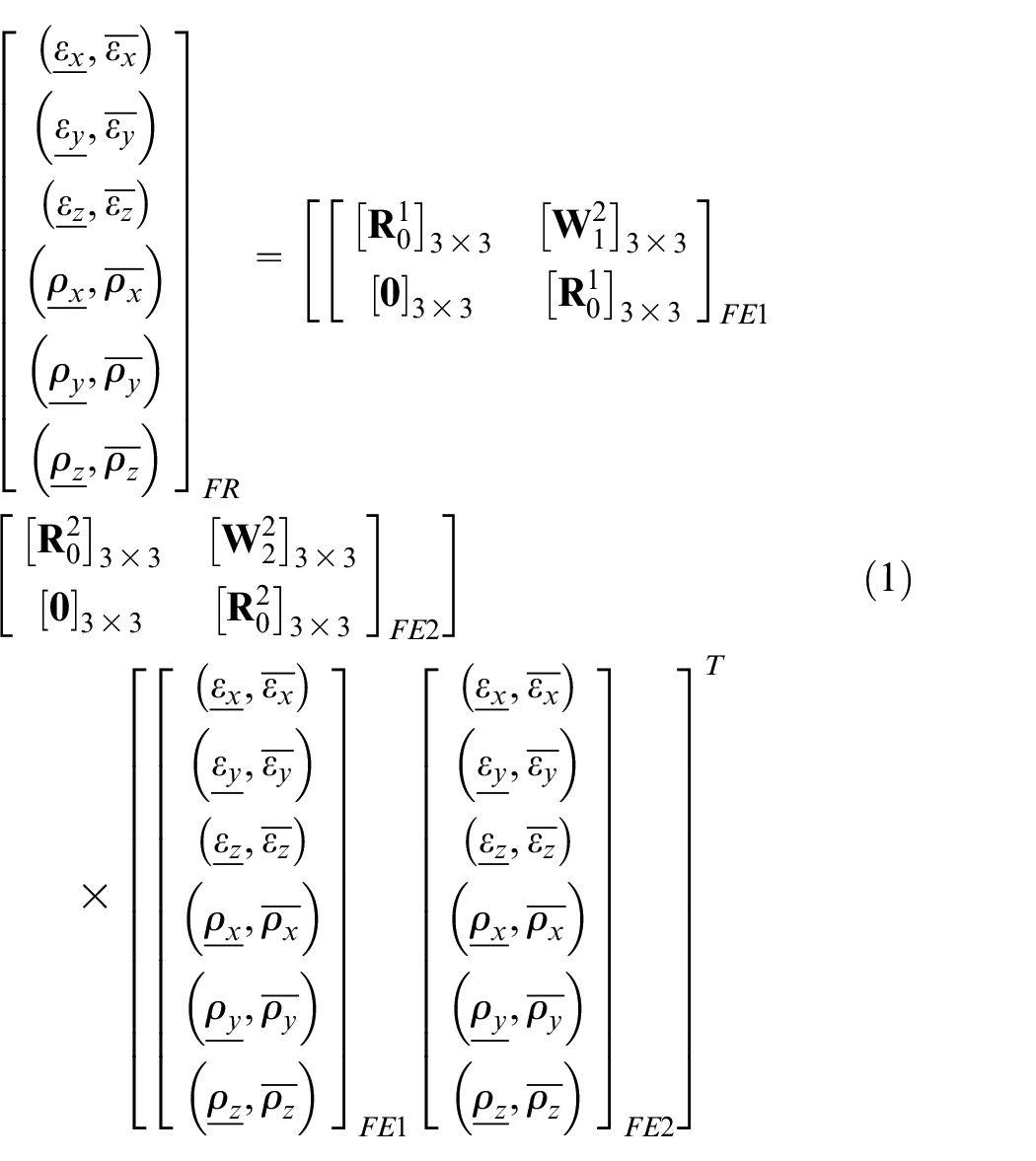
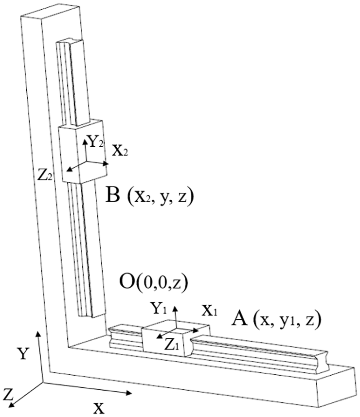
As seen in Figure 2, the X-axis and Y-axis of the machine tool are respectively fixed on the base of the machine tool. The distance between the center of Y-axis slider and the center of X-axis slider is regarded as the FR (functional requirement) of the component elements of dimension chain. The expression of FR can be written as following:
Where
Interaction analysis of geometric errors between different axes.
Here, TX and TY are the straightness error of the guide, and TX = TstX+
The expression of

Where,
The expression of FR in Y direction in the base coordinate system of machine tool can be written as:

Where,
From equations (2) and (3), geometric error in the X direction could be affected by the Y-axis motion of the machine tool, and the error in the Y direction could be affected by the X-axis motion of the machine tool, that is, the geometric error of each axis is comprehensively affected by the mutual motion of each axis of the machine tool. The kinematic Jacobian-Torsor model can better express the error variation range under the interaction of multi-axis. Compared with the previous expression, the kinematic Jacobian-Torsor model can continuously express the functional requirement with the change of position, and it is quasi-static at the error sampling position for each sampling step in time domain.
The Torsor expression of the geometric features within machine tools
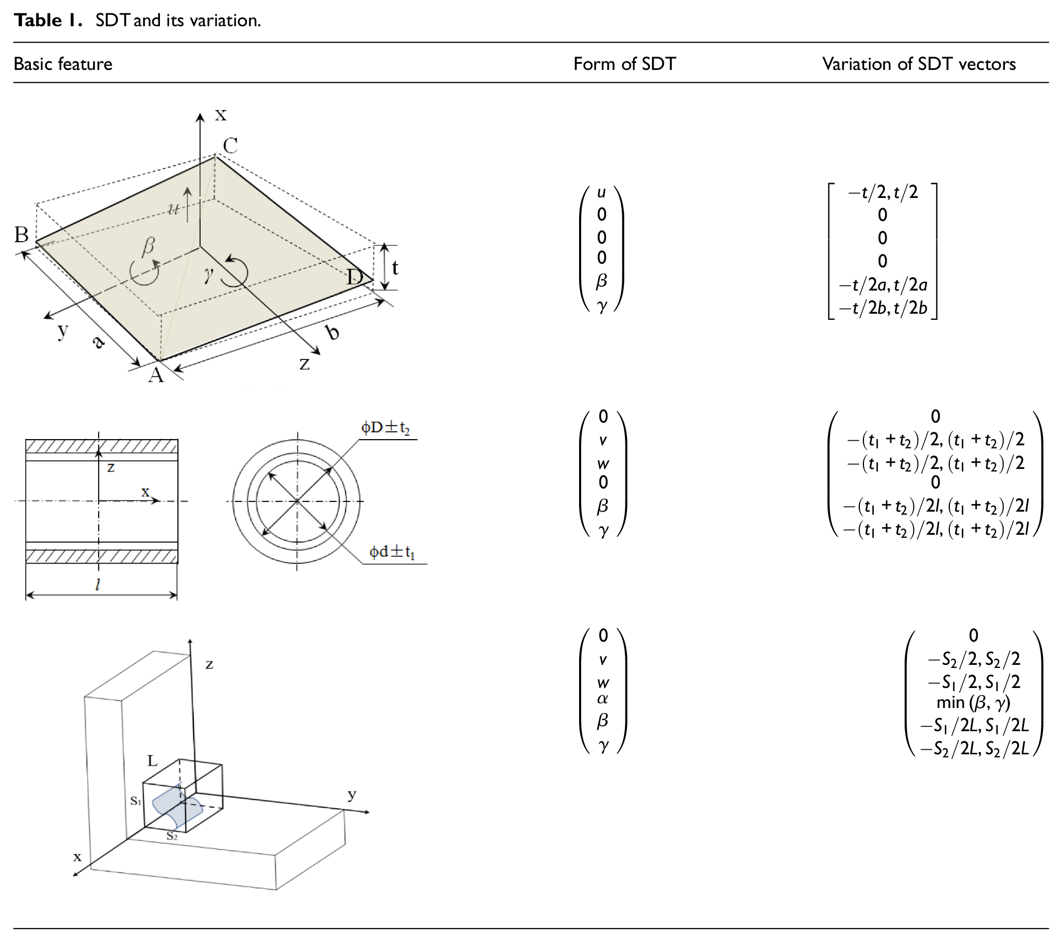
The machine tool contains many different types of assembly features, such as plane, cylinder, linear object and so on. Different types of assembly features correspond to different expressions of torsors. And sometimes even the same assembly features can correspond to different torsor expressions when describing different assembly paths. This situation is especially obvious when the assembly contains parallel structures. The assembly structure of machine tool contains lots of parallel structures, so the previous studies about this model only considered a serial connection in assemblies may not suitable. According to this, details about the different types of geometric features within the machine tool and the corresponding SDT are presented in Table 1.
SDT and its variation.
Procedure of the geometric error modeling of machine tools under the interaction of multiple axes
Based on the proposed kinematic J-T (Jacobian-Torsor) model, the main procedures of the geometric error modeling of machine tools considering the interaction influence of multiple axes are shown in Figure 3.
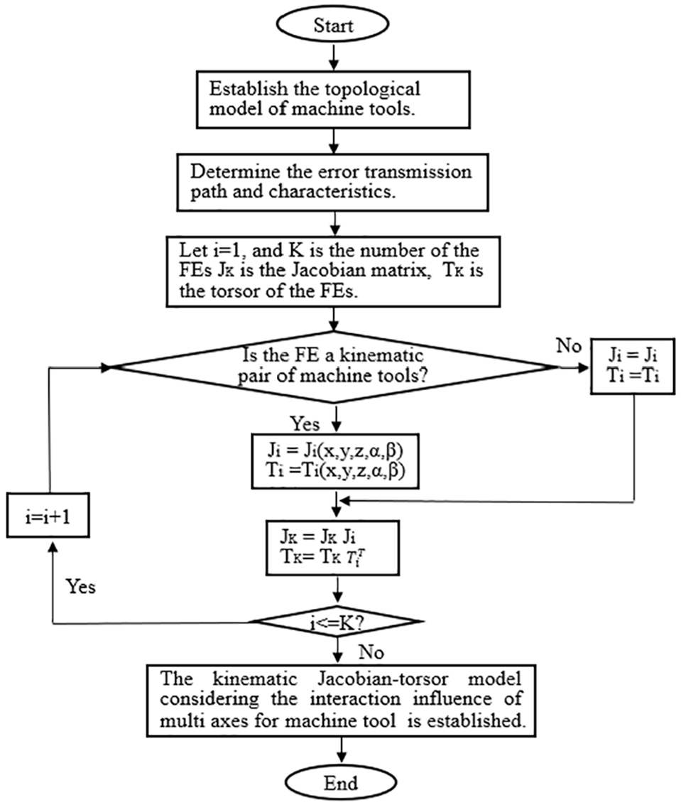
Procedure of the geometric error modeling of machine tools under the interaction of multiple axes.
Application of kinematic Jacobian-Torsor model
The classical Jacobian-Torsor model combines the advantages of the torsor model in the represent of the tolerance and the Jacobian model in the propagation of the tolerance, it fits the complex assemblies which contain abundant joints and geometric tolerances well in a static state. However, the machine tool is always under kinematic conditions in the machining process, the feature type, the tolerance value, the position, and the transfer path of the features in the assembly will change accordingly. According to formula (2), the change of feature position will cause the change of feature error transmission path, so that resulting in “leverage effect.” Considering the variation of Jacobian matrix and torsor model under kinematic state, the kinematic Jacobian-Torsor model of machine tool error can be established. The structure and topological graph of a four-axis horizontal machining tool are shown in Figure 4. The connection graph of functional pairs is shown in Figure 5.
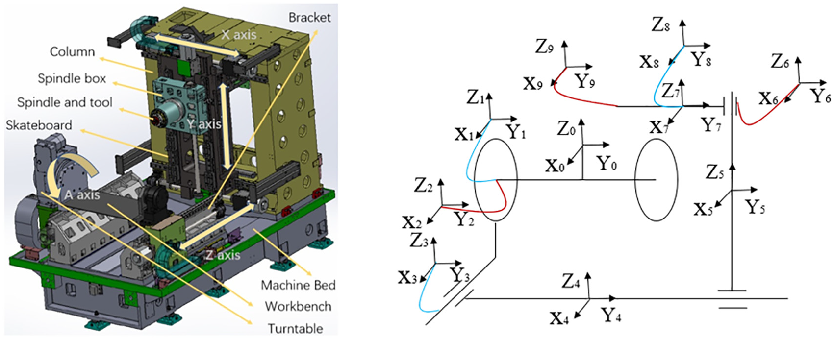
The structure and topological graph of the horizontal machining center.
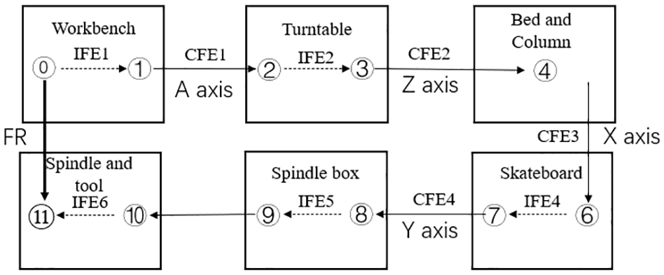
Connection graph of functional pairs.
The kinematic J-T model is built based on the connection graph of functional pairs. The direction of tolerance propagating is along the route IFE1-CFE1-IFE2-CFE2-CFE3-CFE4-IFE3-IFE4. The Jacobian matrixes and the corresponding tolerance torsors are presented in Table 2. Here, IFE means functional requirement inside a component, CFE Indicates the functional requirement where two components are in contact.
Jacobian matrixes and deviation torsors.
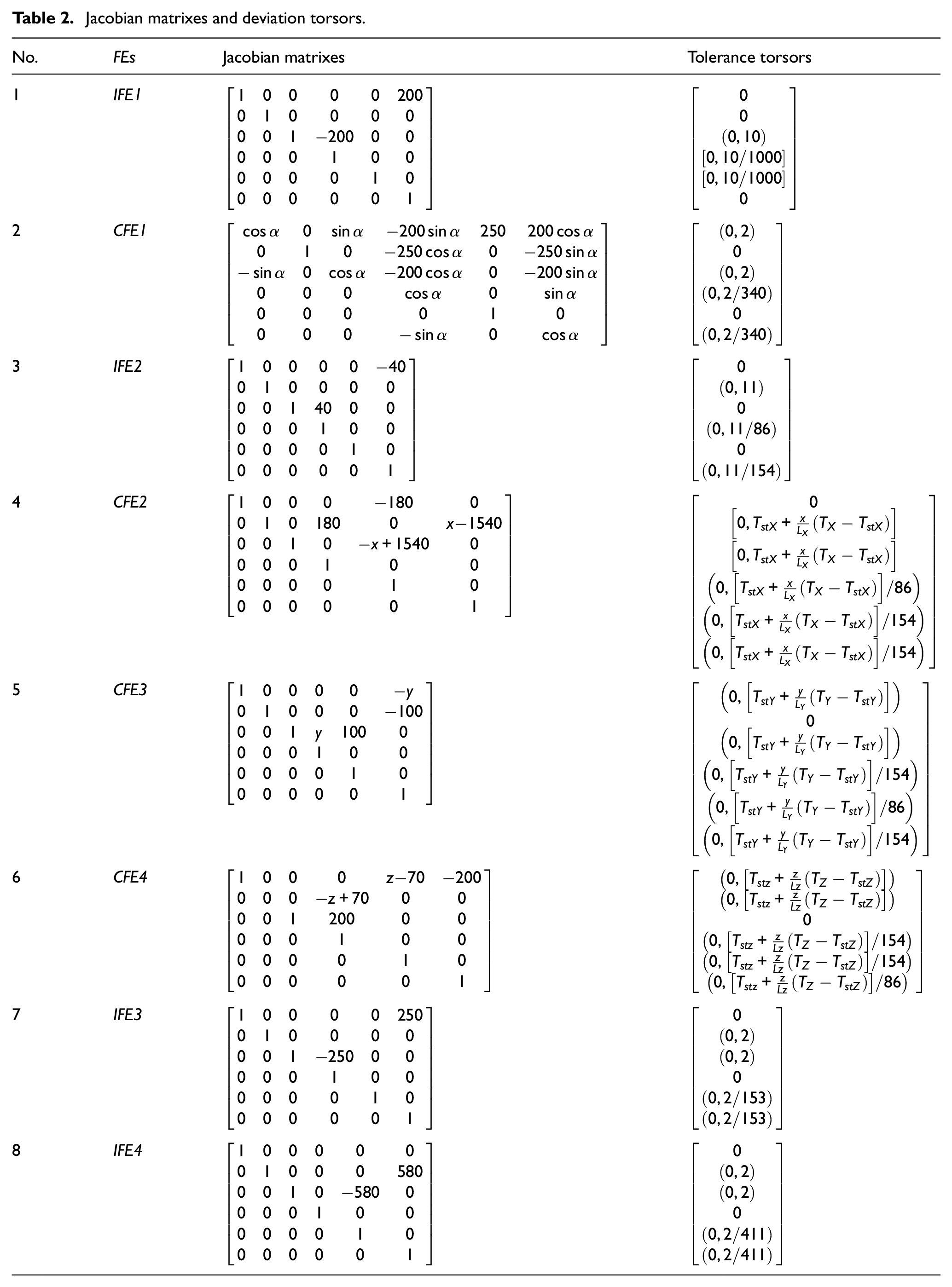
According to the kinematic Jacobian-Torsor model and the expressions of the Jacobian matrixes and the tolerance torsors in Table 1, the value ranges of x, y, and z are [160, 960], [0, 800], and [−282, 418] respectively. Z = 70 is the Z coordinate value of the zero point of the machine tool. The expression of the spindle and tool tolerance in X direction in the table coordinate system can be written as:


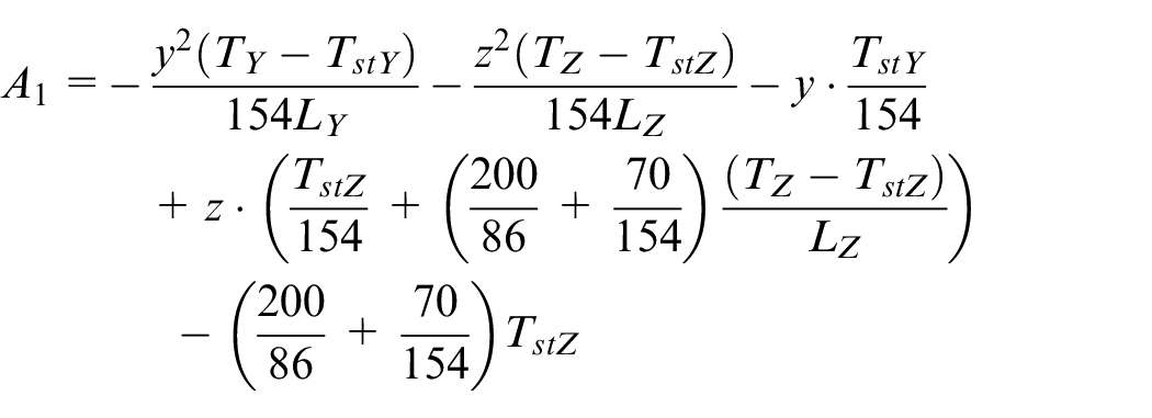
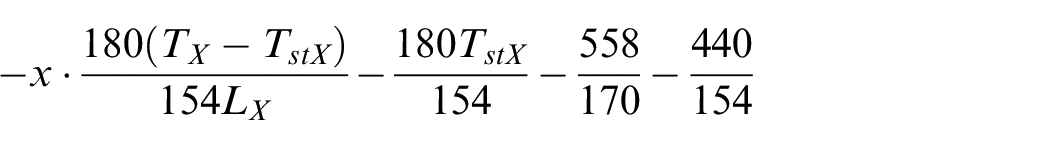
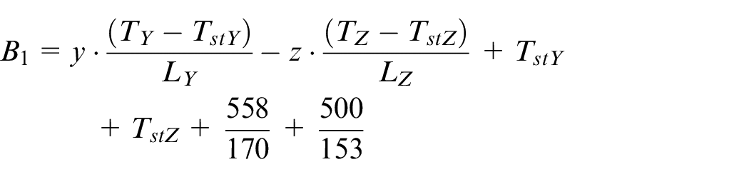

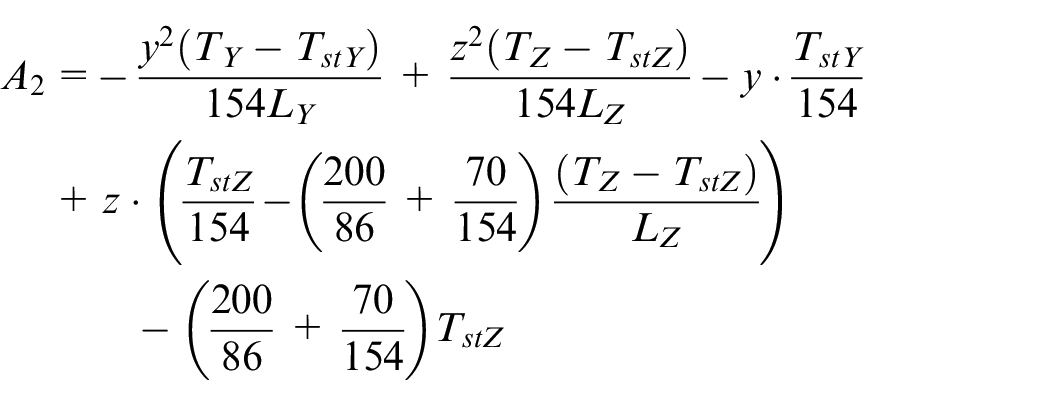
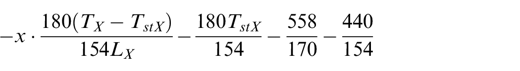
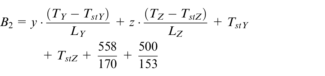

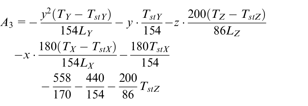
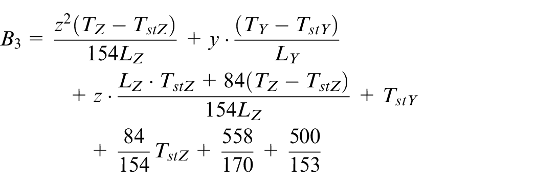
Here, TX, TY, and TZ are the profile error of the guide contacted to the slider, and TX = TstX + xθ, θ = ( TX − TstX)/LX. LX is the total stroke of the x axis length of the guide, TstX is the profile error of nominal length of guide. As for the parameters with a subscript of Y or Z, their meanings are similar to that of X.
Experimental verification and discussion
In order to validate the proposed kinematic Jacobian-Torsor model in geometric error modeling considering the interaction influence of multiple axes for machine tool, experiments were carried out. In order to verify the influence of X-direction positioning error on
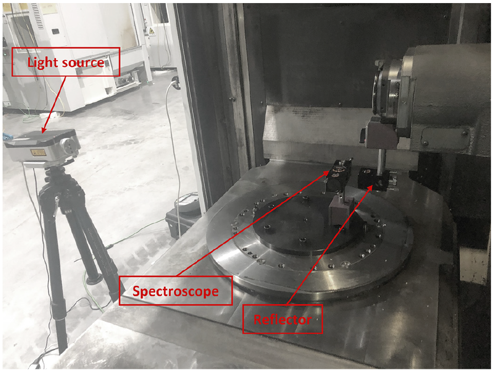
The measurement setup of the experiment for X-axis.
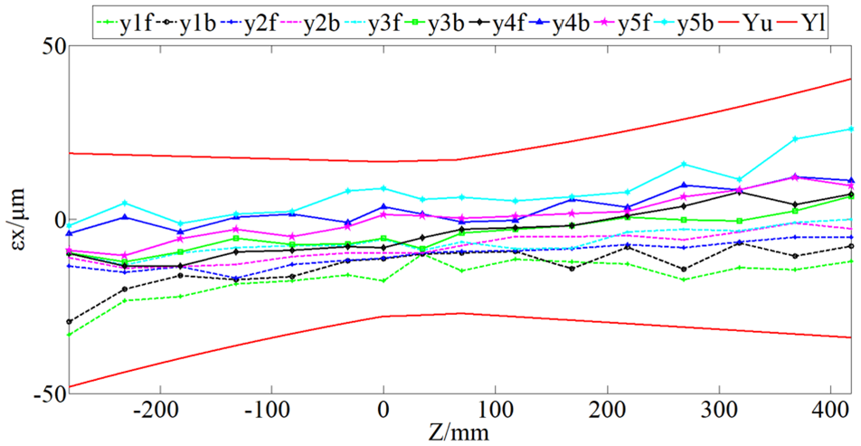
As shown in Figure 7, the movement variation of geometric errors along X axis are figured out both for the modeling based on the proposed kinematic Jacobian-Torsor model and for the measured results in validation experiments. In the figure, the Yu and Yl are the upper bound and the lower bound of the tolerance range obtained by the geometric error model based on the kinematic Jacobian-Torsor model. The yif and yib (i = 1,2,3,4,5) are the measurement results of the machine center when there are forward movement and backward movement along the straight axis. It can be observed that all the curved surfaces of the positioning error in experiments are within the tolerance range gotten by the model.
Multiple measurements of the X-axis positioning error of the machine tool SH501.
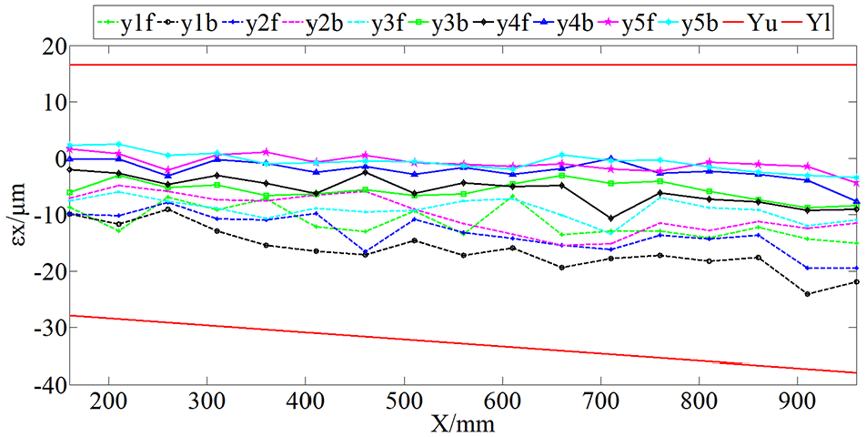
In order to verify the influence of Y-direction straightness and Z-direction straightness error on
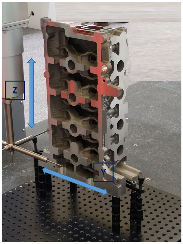
The flatness of the milled plane is measured on CMM.
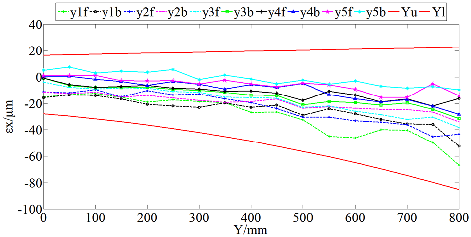
The measurement results of flatness in Y and Z directions are shown in Figures 9 and 10 respectively. It can be observed that all the curved surfaces of the straightness error in experiments are within the tolerance range gotten by the model and its trend is also consistent with the model.
The flatness of the milled plane along with the Y-axis.
The flatness of the milled plane along with the Z-axis.
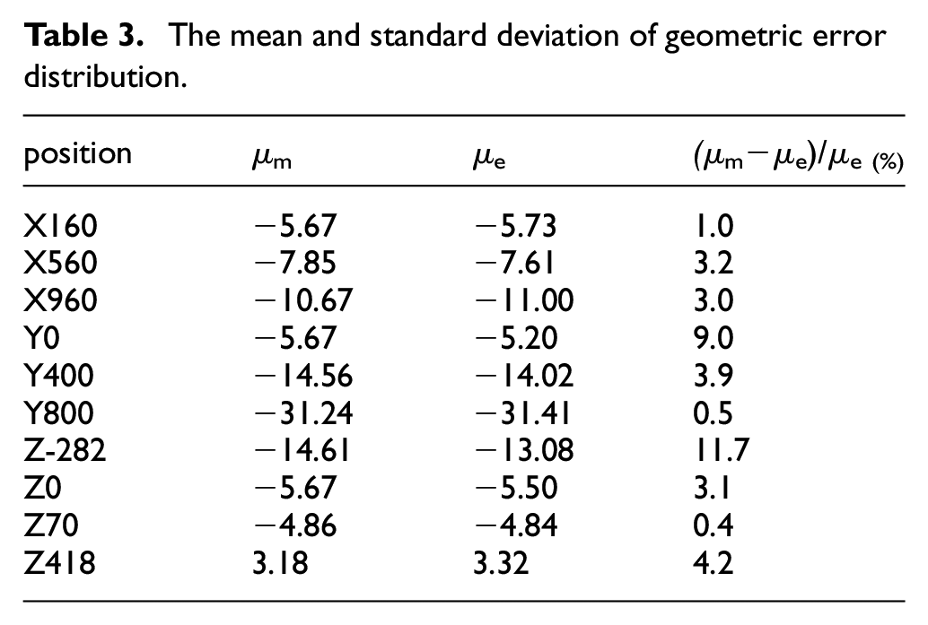
In order to prove the effectiveness of kinematic Jacobian-Torsor model in the interaction analysis of geometric tolerance of multi-axis machine tools, the influence of X, Y, and Z-axis on
The mean and standard deviation of geometric error distribution.
Conclusions
In this paper, a modeling methodology to describe the relationship between the range of machine geometric tolerance and the motional domain of machine tool axes based on improved Jacobian-Torsor theory is developed. Based on the proposed kinematic Jacobian-Torsor model, the geometric error model of multi-axis machine tool considering the interaction influence of multi axes is given and validation experiments are carried out on five machine tools to verify the effectiveness of proposed method. A good agreement for tolerance range between simulation and experimental results can be seen, that validate the proposed kinematic Jacobian-Torsor model for spatial geometric error expression.
Several advantages of the proposed methodology can be drawn as following: (1) The non-uniformly distributed geometric error of multi-axis machine tool considering the interaction influence of multiple axes for machine tool can be spatially and continuously expressed for each different moving position in space domain. (2) It can be applied for different types of machine tools with different configurations, thus providing a thermotical guidance for comprehensive tolerance design of machine tools. (3) Furthermore, according to the variation trend of errors, the machine tool error can be compensated correspondingly thus to improve the machine tool accuracy.
Footnotes
Declaration of conflicting interests
The author(s) declared no potential conflicts of interest with respect to the research, authorship, and/or publication of this article.
Funding
The author(s) disclosed receipt of the following financial support for the research, authorship, and/or publication of this article: This project is supported by the National Natural Science Foundation of China under the project No. 51975369, the National Key Science and Technology Research Program of China under Grant No. 2019ZX04027001, and China Postdoctoral Science Foundation under Grant No. 2020M681291. The authors would like to thank these financial supports.