
Abstract
An integrated manufacturing system needs automated conversion of design information into its manufacturing counterpart. This is partly dealt with in the present study for extracting the manufacturing information for computer-aided process planning systems, including the identification of tool approach direction, attributing the dimensional and geometric tolerances to the machining features, and identification of the reference faces. In spite of extensive study conducted on computer-aided process planning systems, further investigation is still needed to develop automation in attributing tolerances to machining features and identifying the reference faces. The authors have proposed new methods to implement these tasks. A detailed case study has been used to illustrate the application of the developed algorithms.
Keywords
Introduction
Computer-aided design (CAD) and computer-aided manufacturing (CAM) systems are employed in industry with the aim of reduction of the time and costs of product design and manufacture. However, the gap existing between CAD and CAM is considered as an obstacle which is tried to be overcome by developing computer-aided process planning (CAPP) systems.1 –3 A competent CAPP system can help the design information be properly and efficiently converted into its counterpart manufacturing information. 4
The machining features, tool access direction (TAD), dimensional and geometrical tolerances, surface characteristics such as roughness and hardness are the major information which is dealt with in CAPP systems. These pieces of information are expected to be provided through the CAD system. Unfortunately, CAD systems do not efficiently support all these categories of information and they have to be separately input by the user to the CAPP system. 5
As far as the machining features are concerned, different methods have been developed for recognizing the machining features, such as syntactic pattern recognition, state transition diagrams and automata, logic (if–then) rules and expert systems, graph-based approach, convex hull volumetric decomposition, cell-based volumetric decomposition, hint-based and hybrid approaches.6 –9 It should be noted that the topological data of the workpieces are used for recognizing the machining features and TAD.
Obtaining the dimensional and geometric tolerances from CAD databases has already been discussed by some researchers. Shah et al. 10 employed dimension graphs for the dimensional and geometric tolerances that could be used in both CAD and CAPP. The dimension graphs were first generated from a feature-based design system and then the tolerances were transferred to the relevant machining features. In this method, the reference surfaces of the tolerances were distinguished. Vosniakos 11 and Prabhu et al. 12 proposed a method for the automatic extraction of geometric and non-geometric information from two-dimensional engineering drawings. However, distinguishing between the reference surface and the machining face has not been tackled. Gao et al. 13 suggested algorithms for obtaining the dimensional and geometric tolerances from three-dimensional (3D) designs created in Pro/Engineer and converting them into the machining feature data. Their algorithms are based on special formats for saving annotations in Pro/Engineer. These formats are not supported by other CAD systems. In addition, the reference and machining faces are not distinguished. The tolerances are obtained when CAD model is created. This can raise difficulties because of the changes that usually occur during process planning. In some studies, the dimensional and geometric tolerances are directly attributed to the relevant features when inputting the information into the CAPP system. Zhou et al. 14 also discussed about the recognition of features and their parameters, the processing of technical information, and requirements of process planning.
It has been endeavored in the present study to meet the requirements of an automated system integrating CAD and CAPP, as a step toward partially filling the gap existing in the literature. An integrated approach has been introduced for automatic recognition of machining features, identification of their TADs, and attributing the dimensional and geometric tolerances to the relevant machining features. The proposed system embodies new methods for TAD identification and attribution of the tolerances. The reference faces are also determined for the dimensional tolerances of the features. The application of the proposed algorithms has been illustrated by a detailed case study.
Outline of the proposed system
In order to develop an integrated manufacturing system, the topological information of the workpieces designed in a CAD system should be first converted to the manufacturing information which is subsequently processed in CAPP. The 3D model of workpiece had to be used as it accommodates much data on the geometry and topology information. 15 The workflow of a typical integrated system is illustrated in Figure 1. In this figure, the input is the 3D CAD model embodied in a neutral file (STEP) and also other design information such as the dimensional and geometric tolerances which are not supported by CAD packages. The input to the CAPP system is converted to the manufacturing information in a preprocessing module where the machining features, TADs, dimensional and geometric tolerances, and reference faces are identified as intermediate output. The output is then processed in the next module which deals with machining sequencing, setup planning, selection of machine tools and machining parameters, and tooling design.
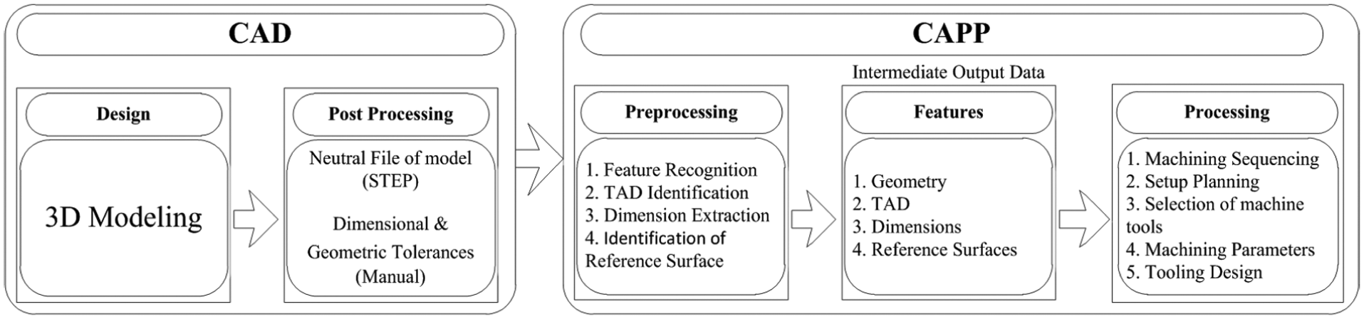
Workflow of an integrated system.
The dimensional and geometric tolerances are manually input to the system on the basis of the following formats


where FM indicates the face to be machined, RF the reference face, TT the type of tolerance, TV the tolerance value, and RF* is indicated for those tolerances needing reference face.
It should be noted that two categories of dimensional and geometric tolerances can be distinguished which consist of tolerances needing reference face and tolerances needing no reference face.16,17 As examples of the geometric and dimensional tolerances which are expressed with reference to their reference faces are parallelism of a face which is measured with reference to another face, or the distance of a face from another face. As examples of the geometric and dimensional tolerances which are expressed without reference are the flatness of a face and the diameter of a hole. In the present study, the tolerance of hole diameter is only considered to belong to the category of dimensional tolerances without reference face. The tolerance of hole diameter is also input on the basis of the second format. This will be explained later in this article.
For the parallelism, a typical example of the input format would be [1, 2, “parallelism,” 0.5] where “1” indicates the face to be machined, “2” denotes the reference surface, parallelism is the type of the tolerance, and “0.5” mm is the tolerance value. For the flatness, a typical example of the input format would be [1, “flatness,” 0.5] where “1” indicates the face to be machined, flatness is the type of the tolerance, and “0.5” mm is the tolerance value. As far as the dimensional tolerances are concerned, it is not needed to distinguish between the reference face and the face to be machined as would be later explained in this article.
The entities such as vertices, edges defined as geometric CAD data are used to identify machining features which are considered as manufacturing entities required for process planning. A machining feature being formed from vertexes, edges, and faces actually represents the volume of raw or semi-finished material that must be removed by tool motion.6,7 Figure 2 lists 10 machining features being recognized in the proposed system and their tool approach directions. Graph-based approach 18 has been used for the recognition of features.
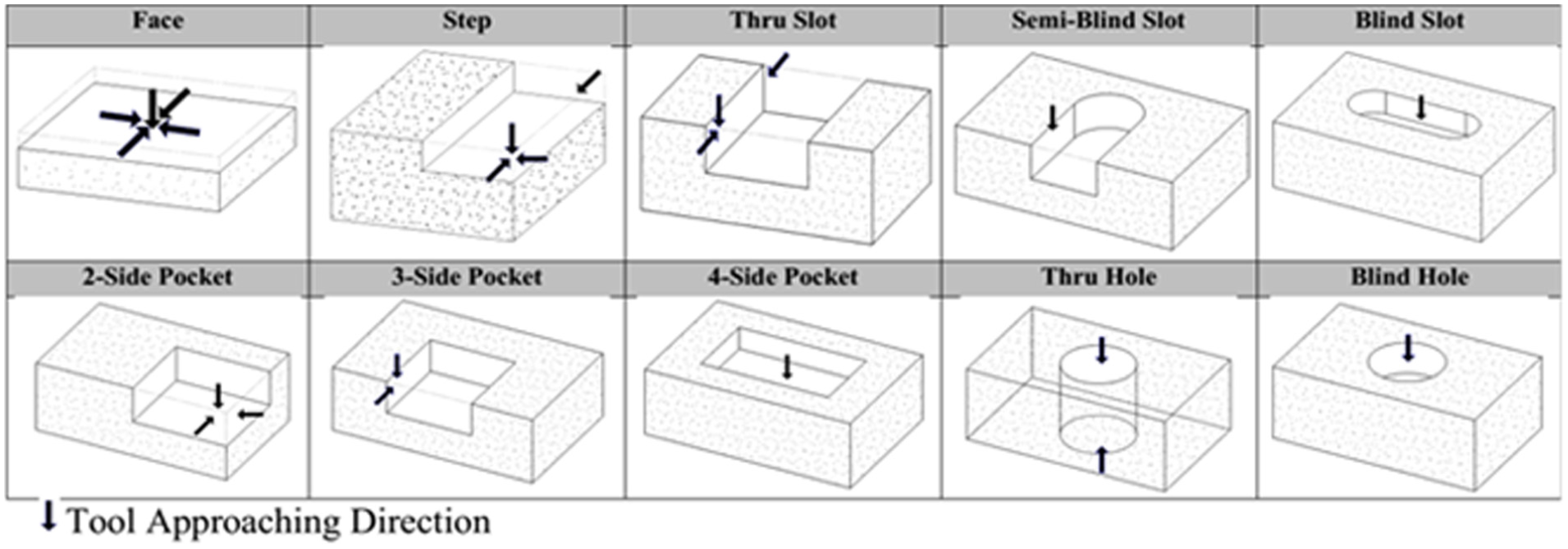
Examples of machining features.
Identification of the tool approach direction
The TAD of a machining feature indicates a path along which the cutting tool can move and approach the machining zone without being obstructed by any part of the workpiece. A machining feature can have one or more TADs. The TAD of a feature is an important parameter in setup planning, which influences the number of setups and the accuracy of machining.19,20
It may turn out that all possible TADs of a machining feature by itself may not be accessible if the other entities of the workpiece are also taken into consideration. For example, the three-side pocket feature illustrated in Figure 3(a) has two TADs shown by arrows. One of these two TADs is not accessible by the cutting tool when the pocket feature is considered together with other entities of the workpiece as shown in Figure 3(b). It can be concluded that both the faces of the feature and those of the workpiece should be taken into account when identifying the TADs. The identification of TAD is thus implemented in two steps: first, on the basis of the feature surfaces; second finalizing the identified TADs and excluding those having interference with the workpiece surfaces.
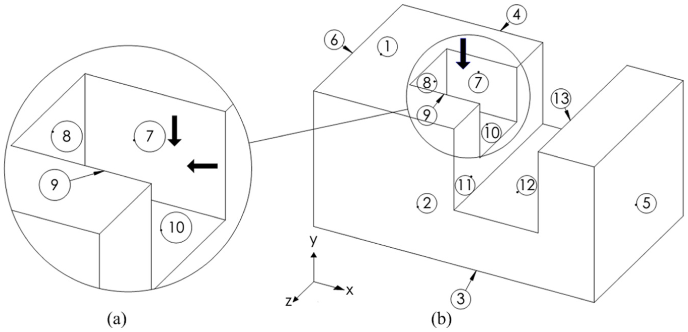
TADs of a machining feature: (a) based on the feature itself and (b) based on the workpiece.
Among the topological entities of a feature and a workpiece consisting of vertices, edges and faces, the faces are only taken into consideration to identify the TADs of the feature. In order to elaborate the method used in the present study for TAD identification, a single face is taken into consideration as shown in Figure 4(a). The opposite of the normal vector of face A is assumed to be a TAD. For investigating the effect of adding other faces, another single face B is inserted. This face can assume three different orientations relative to face A. If face B is inserted parallel to face A as illustrated in Figure 4(b), the opposite of the normal vector of face A can no longer stand as a TAD for this face; the face B gets in the way of cutting tool motion toward face A. A similar situation prevails when an inclined face B is inserted as shown in Figure 4(c). However, the assumed TAD can still stay in place when face B is inserted perpendicular to face A. This case is shown in Figure 4(d).
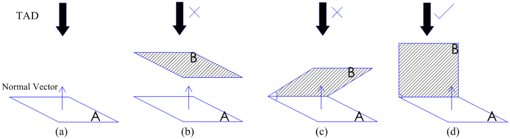
Effect of adding face B: (a) TAD of face A before adding face B, (b) adding face B in parallel to face A, (c) inserting face B inclined to face A, and (d) inserting face B perpendicular to face A.
A surface topology matrix (STM) can be used as a tool to define the orientation of a workpiece’s surfaces relative to each other. In other words, the STM indicates parallel, inclined and perpendicular surfaces of a workpiece.
The STM is defined as follows
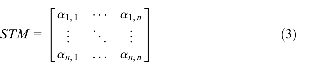
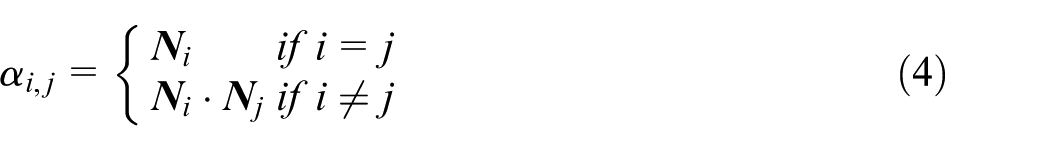
where
According to the foregoing discussion, the opposite of the normal vector of a face whose relevant row and column entries in the STM are all zero is regarded as a TAD. All other faces are perpendicular to this one which is called as a “tool face.” As an example, the STM for the three-side pocket feature of Figure 3 is shown in Figure 5. According to this matrix, this feature has two tool faces, that is, faces 8 and 10. The TADs of the feature are thus directed along
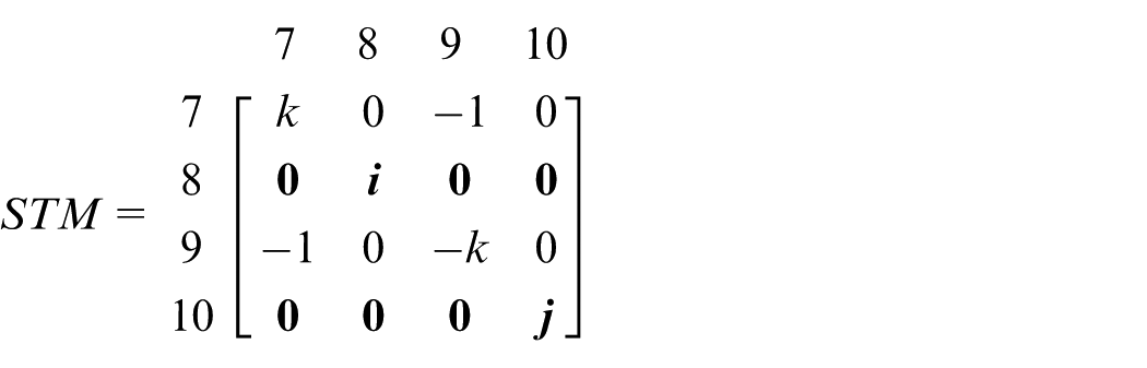
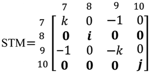
STM for the three-side pocket in Figure 3(a).
As already explained, the TADs identified for a standalone feature may have interference and thus be unusable when that feature is considered as a portion of a workpiece. All the workpiece’s surfaces which are parallel or inclined to the feature’s tool face may impede the tool access to this face. In order to identify these unusable TADs, the workpiece’s surfaces being parallel or inclined to the tool faces are determined from an STM developed for the workpiece. The tool faces are then projected along their normal vectors, on these surfaces. A projected tool face falling within the boundaries of the said surfaces implies that its TAD is unusable and should be dropped from the list of possible TADs. An acceptable TAD necessitates that the relevant projected tool face to fall outside the boundaries of the said surfaces. The existence of common area between any of these surfaces and the projected tool face implies that the cutting tool cannot access the whole points of that tool face. In the example of Figure 3, the direction −
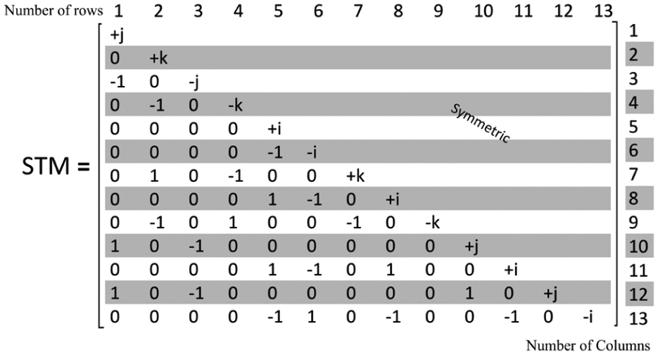
STM for the workpiece shown in Figure 3(b).
The proposed approach works on the basis of the normal vectors of faces. This can cause problem when features such as a thru hole are encountered. The latter does not have any surface normal to its axis at the bottom or the top and thus do not present any normal vector along its axis. Therefore, its TAD along the axis cannot be detected. As a remedy, a virtual surface normal to the hole axis is added. This surface is then used in a similar way as the other surfaces for identifying possible TAD along the hole axis. Both directions of the vector normal to the added surface are taken into consideration for identifying possible TAD in either of these directions. The procedure is illustrated for a thru hole and a thru slot in Figure 7. It should be noted that for the technical purpose of programming, a cylindrical face is virtually divided into two semi-cylindrical faces. The normal vector of the semi-cylinder is randomly placed at a point on the cylindrical face so that the components of the vector to be nonzero.
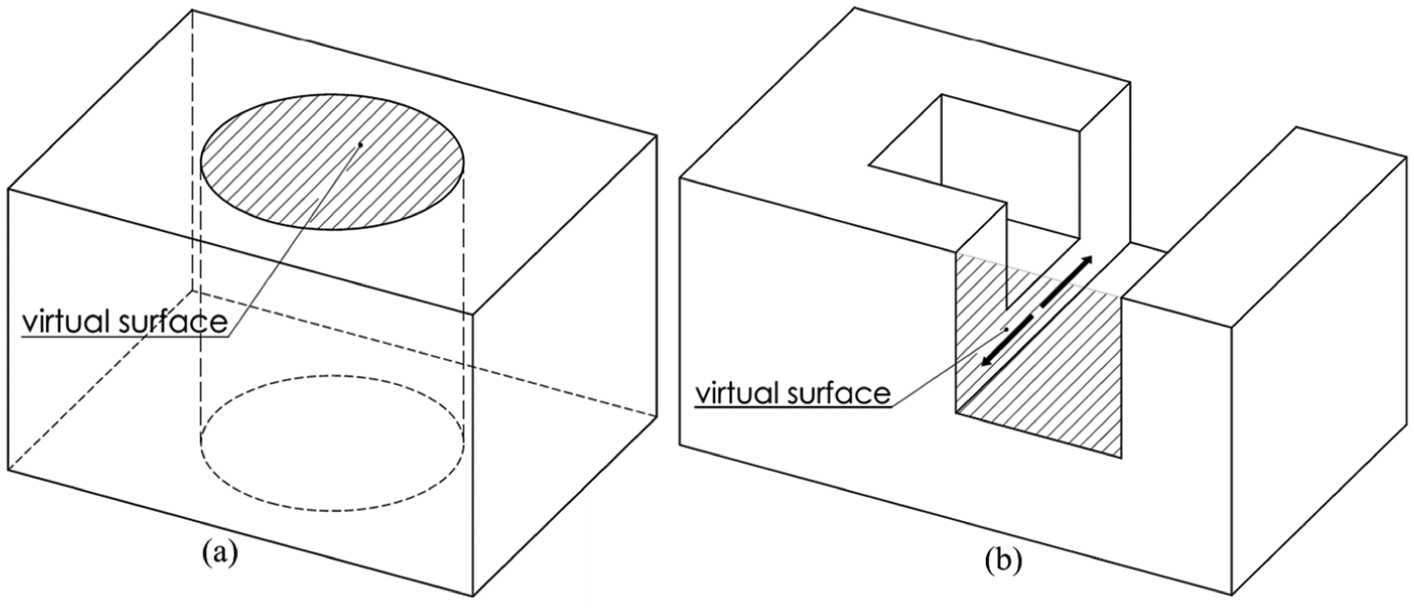
Virtual surfaces: (a) thru hole feature and (b) thru slot feature.
The algorithm for identification of TADs is as follows:
Geometric information: Identify all features. Create STM for the workpiece.
TAD identification based on the feature proper: Call the ith feature ( Find those surfaces of the feature all the row entries of which in STM are zero; save these surfaces as the tool faces. Add the vectors opposite to the normal vectors of the identified tool faces to the list of TADs.
TAD identification based on the workpiece: Call the jth tool face of feature From STM, identify those surfaces of the workpiece which are not perpendicular to the tool face. Project the jth tool face to the non-perpendicular surfaces identified in the last step. Check for the existence of common area between each non-perpendicular surface and the projected tool face on this surface. Do this for all non-perpendicular surfaces. If any common area is detected, remove the TAD of the jth tool face from the list of TADs of feature
If
Identification of possible TADs in directions perpendicular to which the feature Determine the directions perpendicular to which If X is null then go to step (e). Add virtual faces to Repeat steps (c)-4 to (c)-5 for either of directions of vector normal to each virtual face; Do this for all virtual faces of
Deriving the dimensional tolerances and reference faces
As already explained in the first section (the outline of the proposed system), the dimensional and geometric tolerances are input by the user to the CAD post-processing module. The input is cast in the form of formats (1) and (2) presented in the first section. The geometric tolerances as expressed in format (1) would provide sufficient information regarding the relevant feature and also the machining and reference faces without any need to further processing. This can be evidenced from Figure 8(a) where, for example, the parallelism of face 3 as a face feature is expressed with reference to face 5 which is another face feature.
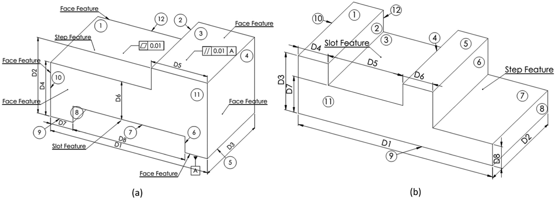
Examples of dimensional and geometrical tolerances: (a) Reference face in dimensional and geometrical tolerances; (b) Ambiguity in determining the reference face in certain types of dimensional tolerances.
As far as the dimensional tolerances are concerned, the relevant feature and the machining and reference faces cannot easily be distinguished by looking at the drawing. For example, tolerance D6 in Figure 8(a) can belong to either of slot and step features. The right decision depends on the machining sequence which is determined in the CAPP processing module of Figure 1. Therefore, the dimensional tolerances need further processing in CAPP after its initial input by the user. This is done automatically as discussed in subsequent subsections.
In some other cases, when both the reference and the machining faces belong to a single feature, the reference face may be evident from the drawing. For example, it is clear from the drawing of the workpiece shown in Figure 8(a) that face 8 among the candidate faces 6 and 8 should be considered as the reference face for tolerance D8, because this face is assigned a machining tolerance, D7. It should be noted that the reference face is not always distinguishable from the drawing even when both the reference and the machining faces belong to one feature. For example, the reference face for tolerance D5 of the slot feature in Figure 8(b) cannot be decided from the drawing. Even when the reference face can be distinguished by the user from the beginning, the program finds the reference face automatically.
Number of standard dimensional tolerances of a feature
In order to attribute the existing dimensional tolerances of a workpiece to its features, it is first needed to determine the number of dimensional tolerances needed for each feature. It should be noted that a special number of dimensional tolerances is needed to characterize the manufacturing requirements of a feature, which is named as number of standard dimensional tolerances of a feature (NSDF).
In the present study, prismatic workpieces are taken into consideration. It is assumed that these workpieces are machined from cubic slabs of the required dimensions. In order to facilitate the determination of NSDF, it is also assumed that the surfaces of the workpiece in hand are perpendicular or parallel to the coordinate planes. Taking into account these assumptions, it can be inferred that each flat face needs one-dimensional tolerance in order to determine its distance (D1) from a coordinate plane (Figure 9(a)). The length and the width of the face are limited with other faces, and therefore, it is not needed to consider any tolerance for them. Each cylindrical or semi-cylindrical face needs 3D tolerances; two for the distances (D1, D2) of the center of the base from two coordinate planes and one for the magnitude of the radius (D3) (Figure 9(b)). The height of the semi-circle is defined when the intersection of other faces of the workpiece is taken into consideration, and thus, there is no need for any further tolerance. If a semi-cylinder face is tangent to two flat planes, the semi-cylinder would need just one-dimensional tolerance (Figure 9(c)). The magnitude of the radius (D3) is defined by the distance between the planes. The position of the base center is determined by the distance D1. The distance from the other coordinate plane (D2) is defined by the position of one of the flat planes.
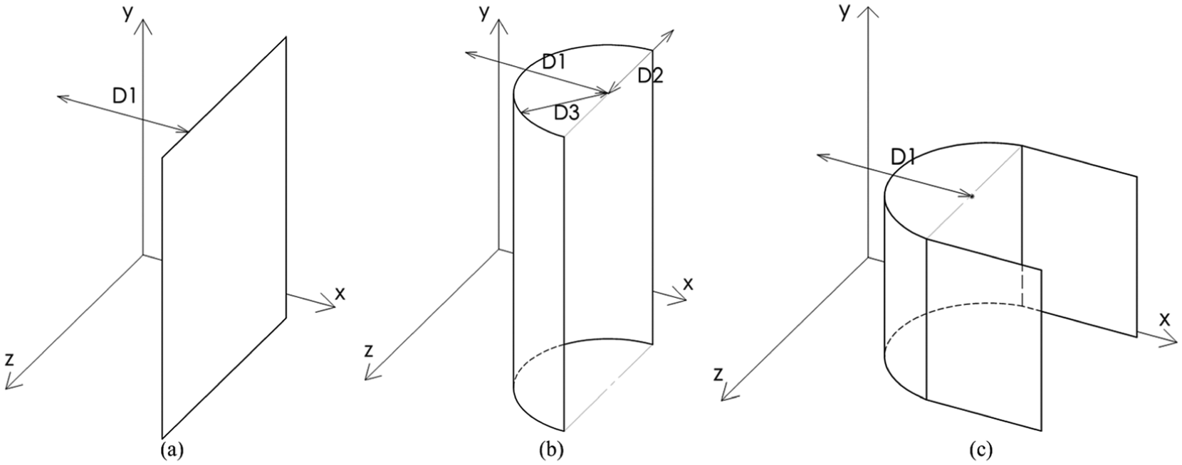
Dimensions with tolerance: (a) for a flat face, (b) for a semi-cylinder, and (c) for a semi-cylinder tangent to two flat planes.
The NSDF of some features is shown in Table 1. The number of dimensional tolerances of a workpiece is calculated as follows
Number of standard dimensional tolerances for features.
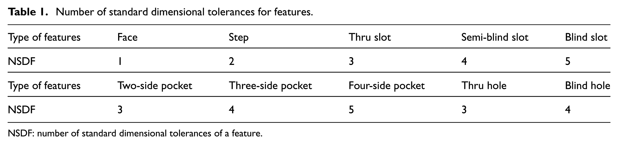
NSDF: number of standard dimensional tolerances of a feature.
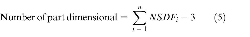
where n is the number of feature constituents of the workpiece. It should be noted that the cubic slab out of which the workpiece is machined is recognized as six facing features each of which possesses one-dimensional tolerance. Therefore, six-dimensional tolerances are attributed to the cube, whereas the cube just needs 3D tolerances. To adjust for this, the number 3 is deducted from the sum of total NSDF in equation (5).
Identification of the dimensional tolerances of features
The identification of the dimensional tolerances of features is explained here with the help of a typical example depicted in Figure 10(a). In this figure, the dimensional tolerances of the step and slot features are presented. These tolerances are input by the user. When the tolerances are called upon within the program, tolerances D4, D5, and D6 are attributed to the step feature. According to the format (2) in the first section (the outline of the proposed system), these tolerances have been arranged in three arrays [1, 9, D4], [2, 4, D5], and [1, 7, D6]. The tolerances D6, D7, and the duplicated tolerance D8 are attributed to the slot feature. They are accordingly arranged in four arrays [7, 1, D6], [8, 10, D7], [8, 6, D8], and [6, 8, D8].
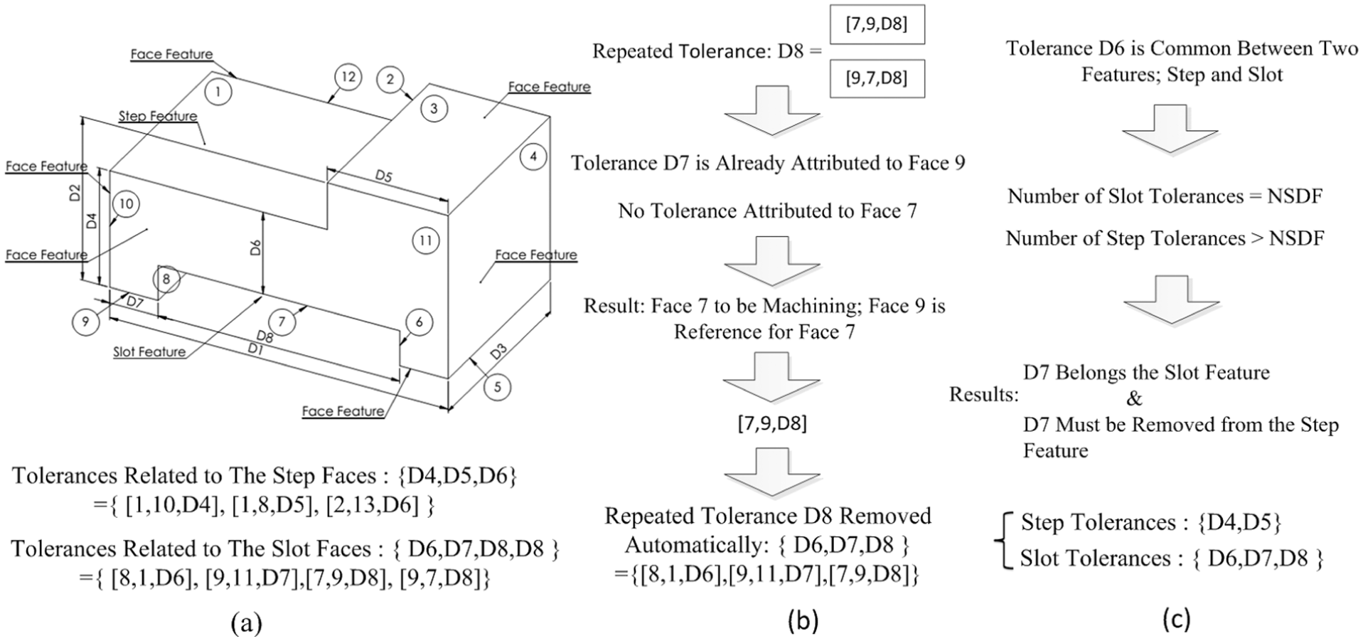
Attributing dimensional tolerances to their features: (a) a typical example of dimensional tolerances for slot and step, (b) removing repeated tolerance, and (c) removing common tolerances.
Two problems are encountered when the dimensional tolerances already input by the user are called upon in the program. The first problem arises when both the machining face and the reference face belong to a single feature. In this case, the dimensional tolerance is saved twice in the database of the feature, each for either of the two faces. For example, both of the two faces 8 and 6 distanced from each other with the tolerance D8 in Figure 10(a) belong to the slot feature. The tolerance D8 is saved twice for the feature, thus appeared repeatedly in two arrays [8, 6, D8] and [6, 8, D8] as is clear from Figure 10(a). The program should be able to drop the repeated tolerance from the data base. The algorithm for omitting the repeated tolerance is presented in Figure 10(b). In this algorithm, one of the repeated tolerances is first omitted, randomly. The reference and the machining faces are then distinguished from each other at a later step when the tolerances are all attributed to their features.
The second problem arises when the surfaces of the dimensional tolerance belong to different features. The example of this kind of problem can be evidenced in Figure 10(a) where the tolerance D6 is common between the step and the slot. It appears as [1, 7, D6] for the step and as [7, 1, D6] for the slot. In this case, the present number of the tolerances of each feature is compared with its NSDF. The common tolerance would belong to the feature whose present number of tolerances is equal to its NSDF. In Figure 10(a), D6 belongs to the slot as it satisfies the said criterion. The algorithm for this decision making is presented in Figure 10(c).
As already mentioned in the first section, the dimensional tolerances which do not need reference surface are input with format (2). This has been made possible because of the way the cylindrical surfaces such as holes are defined. In this case, one of the semi-cylindrical surfaces is considered as face 1 in format (2) and the other is introduced as face 2.
The common dimensional tolerances are omitted as already explained except for the facing tolerances of the six surfaces of the cubic slab. Each pair of the opposing faces of the slab may have one-dimensional tolerance which would be repeated with either of faces once being in the role of machining face and next in the role of reference face. Actually, the face that does not need to be machined should be regarded as the reference face for machining the other face. This is decided during process planning and, thus, the common tolerance is not omitted in this case as a provision to avoid missing a candidate reference face. For example, the tolerance D2 in Figure 10(a) belongs to either of the upper and the lower facing features, that is, face 3 and face 9. Let it be assumed that the said tolerance is attributed to the lower facing feature and the common tolerance is omitted from the upper facing feature. In that case, the faces 3 and 9 would be regarded as the reference and machining faces, respectively. The face 9 would thus be dropped, by omitting the common tolerance, from the list of candidate reference faces. It may, however, be cleared up during process planning that face 9 does not need to be machined and is accurate enough for acting as the reference face for machining face 3. This option has, however, been ruled out by unjustifiably omitting the common tolerance. In order to avoid this, the common tolerances for the slab’s faces are kept pending the process planning.
Briefly, the dimensional tolerances are first attributed to the recognized features during which some tolerances may reappear when the reference and the machining faces belong to one single feature. Some tolerances may also be commonly attributed to two features. The repeated and the common tolerances are subsequently rectified in separate steps. The reference and the machining faces of the rectified repeated tolerances are then distinguished from each other. The algorithm for this procedure can be summarized as follows:
Allocating dimensional tolerances to features: Consider face j of feature i. Identify dimensional tolerances one of the surfaces of which is face j. If face j is the second component of the array, then change its place with that of the first. Otherwise, leave it as it is. Repeat steps 1–3 for all faces of feature i. i = i + 1 If
Omitting repeated tolerance whose reference and machining surfaces belong to one single feature (random omission) Consider dimensional tolerance j of feature i. Change the placement of the first and the second components of dimensional tolerance j and save it in X. If X exists in the list of tolerance of the relevant feature, then omit X. Repeat steps 1–3 for all tolerances of feature i. i = i + 1 If
Omitting tolerances common between features: Identify a feature whose number of dimensional tolerances is equal to its NSDFs. Change the placement of the first and the second components of the dimensional tolerances and save it in X. If X also exists as the tolerance array for another feature, then omit this last tolerance. Find new feature whose number of dimensional tolerances is equal to its NSDF. If the new feature is a face of slab, go to the next step; else go to step 2.
Determination of the reference faces for repeated dimensional tolerances one of which has been removed in stage (b): Identify the repeated tolerances of feature i, one of which has been removed in stage (b). If feature i is a thru or blind hole, return to step 1 (a hole does not need reference face). If the first component of the tolerance exists in other dimensional tolerance of feature, change the placement of the first and the second components. Repeat steps 1–3 for all features.
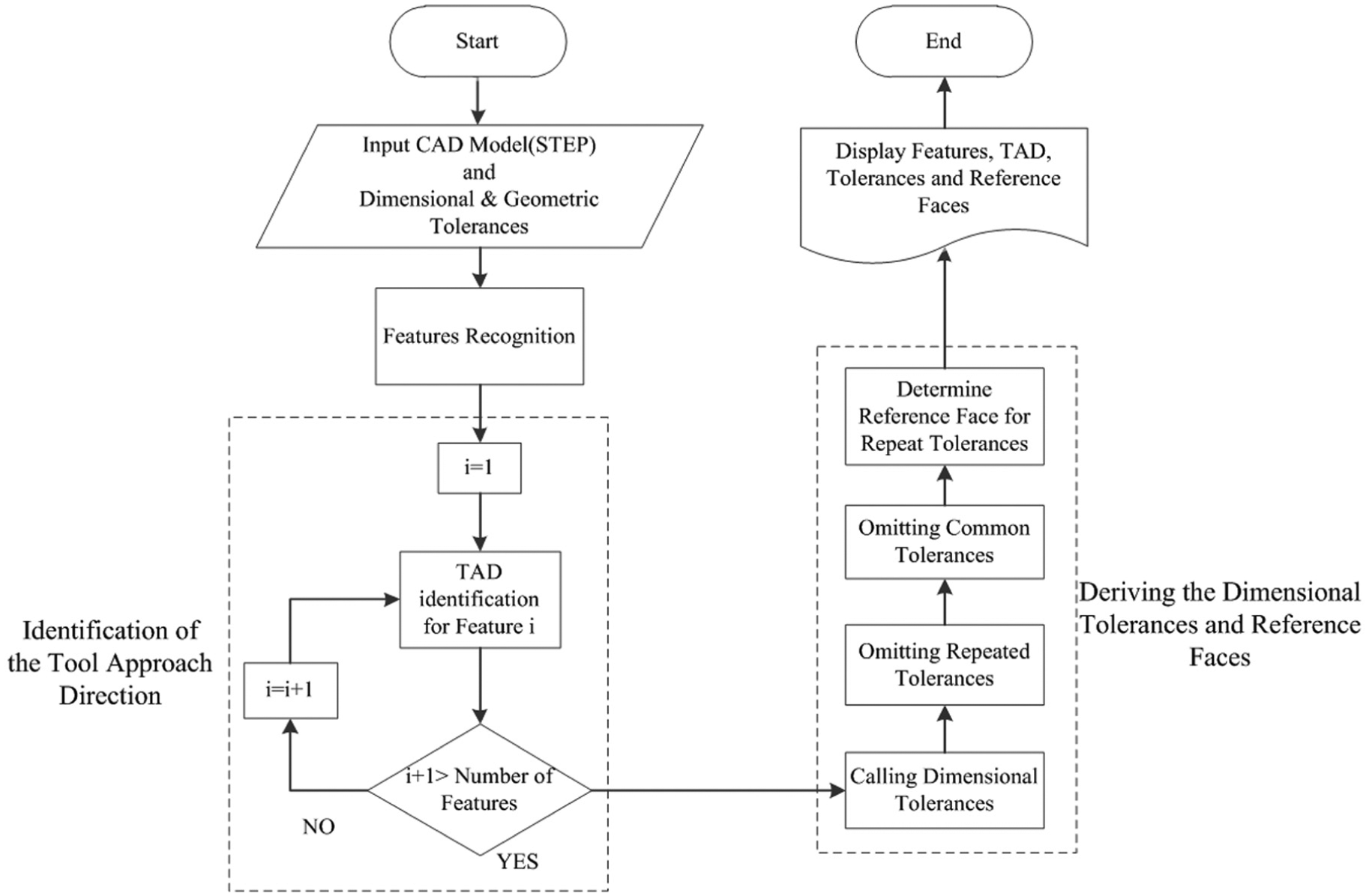
The whole procedure can be evidenced from the flowchart of Figure 11. The sequence of identifying the manufacturing information has been shown in this chart. After inputting the design information such as the CAD model and the tolerances, different features and tool approach directions are identified, tolerances of each feature are determined, and the reference faces are recognized automatically.
Flowchart of program.
Case study
In order to illustrate the application of the proposed algorithm for identification of TAD, dimensional and geometric tolerances, and reference faces of features, a workpiece as depicted in Figures 12 and 13 has been examined. This workpiece possesses 13 features. The tolerances, features, and face numbers are shown in Figures 12 and 13.
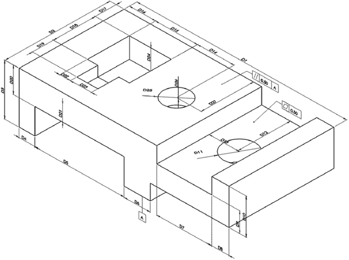
A workpiece with its dimensional and geometric tolerances used for case study.
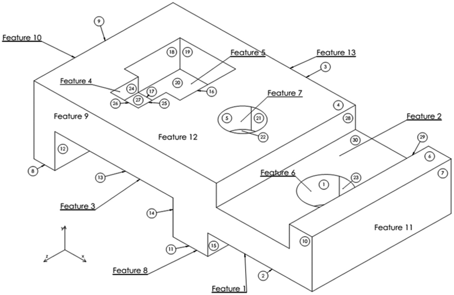
Face numbers and features of the workpiece used for case study.
The results of the application of the proposed algorithms are presented in Table 2. As is evident from this table, the TADs have been identified correctly. For example, the three-side pocket feature which can have two TADs has been assigned just one TAD. The direction posing interference and tool clash has thus been automatically recognized and omitted from the list of acceptable TADs. All the dimensional and geometric tolerances have been attributed to their features. The reference faces have also been determined for all dimensional tolerances.
Results of case study.
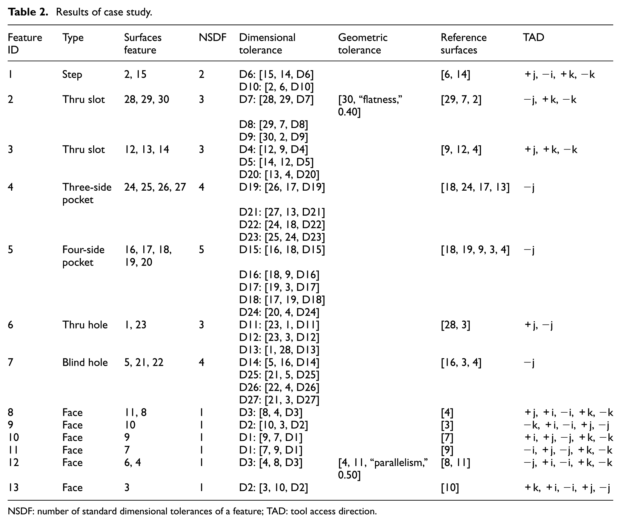
NSDF: number of standard dimensional tolerances of a feature; TAD: tool access direction.
Conclusion
The extraction of manufacturing information of prismatic workpieces from CAD output usable in CAPP systems have been investigated in the present study. New methods were developed for automatically identifying the TADs of the recognized machining features, determining the dimensional and geometric tolerances of the features and faces after initial input by the user, and distinguishing the reference faces of the dimensional tolerances. The TADs of features posing interference with the workpiece’s faces could be identified and omitted from the list of acceptable TADs. The dimensional tolerances of the features have been recognized on the basis of comparison between the extracted tolerances for each feature and its number of standard dimensional tolerances. The application of the developed procedures was illustrated by examining a workpiece consisting of 13 machining features. The proposed method can, of course, be employed for also other complicated workpieces.
Footnotes
Declaration of conflicting interests
The author(s) declared no potential conflicts of interest with respect to the research, authorship, and/or publication of this article.
Funding
The author(s) received no financial support for the research, authorship, and/or publication of this article.