
Abstract
The advantages of well-distributed material flow, easy demolding, and good mechanical interlock structure of the extensible die provide the possibility to be widely used in joining lightweight components. In order to explore the differences in the mechanical properties of the joints produced by different dies, the mechanical behavior of the clinched joints made by the fixed die and extensible dies of 2, 3, and 4 movable segments was investigated in the present study. The process of forming evolution, geometric characterization, failure mode, static strength, joint stiffness, and energy absorption of the dissimilar joints were studied by experimental method. In the clinching process, the neck thickness of joints made by extensible dies can be enlarged by the sliding outward of the movable segments compared with those produced by fixed dies. The failure mode of all clinched joints in this paper is neck fracture. The clinched joints produced by extensible dies of 3 movable segments have the highest static strength in both static tensile and shear tests among the dissimilar joints, which values are 1239.41 and 1259.80 N, respectively. Shearing strength of the joints performed by the extensible dies with 2, 3, and 4 movable segments was increased by 9.84%, 10.09%, and 9.40%, and the tensile strength of those clinched joints was increased by 16.27%, 20.31%, and 14.34% than that of the joints produced by the fixed dies. Experimental have proved that the number of movable segments on the extensible dies has a limited effect on the joint stiffness, tensile strength, and energy absorption of the clinched joints in the cross-lap-tensile test, while it has great effect on the stiffness and energy absorption of the clinched joints in the single-lap-shear test.
Introduction
In recent years, with the development of the automobile industry, global automobile production and ownership have increased significantly, which has had an adverse impact on the environment and human society, mainly manifested in the energy shortage and emission pollution caused by the automobile industry.1–5 Therefore, the automotive manufacturer regards the energy and environmental protection as the core of sustainable development. 6 At present, the development of new energy technologies is not yet prefect. To make automobiles more environment-friendly and fuel-efficient, lightweight technology is one of the most feasible and important measures.7,8 Nowadays, lightweight technology in automobile industry mainly includes three ways: using lightweight materials, optimizing automobile structure, and carrying out process innovation.9–11 As most automobile manufacturers use lightweight materials to reduce automobile weight, the innovation of new joining processes and die structures has become one of the current research focuses.12,13
Aluminum alloy has many excellent characteristics, such as excellent formability, good impact resistance and corrosion resistance, lightweight, high static strength and specific stiffness, etc.14–16 In addition, due to the environmental pollution of polymer plastic products in the recycling process, the price and safety of magnesium alloy materials, and other limitations, aluminum alloy materials have become one of the most ideal materials for automobile lightweight in the automobile manufacturing industry.17,18 Nowadays, the main materials used in the automobile body lightweight structure manufacture field are AA5052, AA5182, AA6061, AA6111, and high-strength steel sheets.19,20 However, the joining of aluminum alloy materials has always been an obstacle to restrict the application of aluminum alloy. 21
There are several commonly methods, such as self-pierce riveting, spot welding, friction stir welding,22–24 ultrasonic-assisted friction stir welding,25,26 laser welding, adhesive bonding, and mechanical clinching, which conventionally can be implemented for joining aluminum alloy materials and other lightweight materials.14,27–30 However, many technologies consume considerable resources and produce pollution gases, and even damage the materials. 31 The mechanical clinching process is the most economical and direct method of the aluminum alloy joint forming process. Compared with the conventional joining method, in addition to prominent advantages of economy, energy saving, environmental friendly,3,19 mechanical clinching also has excellent mechanical properties, particularly the fatigue property. 13 Mechanical clinching is also suitable for joining the heterogeneous and special-shaped covering parts with coating or paint on the surface of the material. Therefore, mechanical clinching has become one of the most important methods for joining the aluminum alloy sheets and other lightweight materials, which accelerates the process of automobile light-weighting to the greatest extent.
Mechanical clinching process is to extrude two or more layers of sheets by punch, and generated an appropriate material flow by means of fixed die or extensible die in order to produce an interlock structure between the joined sheets, namely mechanical interlock that can hook the sheets together.32–34 In the automotive industry, the investigation on the forming mechanism of aluminum alloy sheet is of great significance to solve the problems of aluminum alloy connection and lightweight materials by joining technology. Especially, analyzing the effect of dissimilar dies is very important to evaluating the quality of aluminum alloy joints and revealing the forming principle.
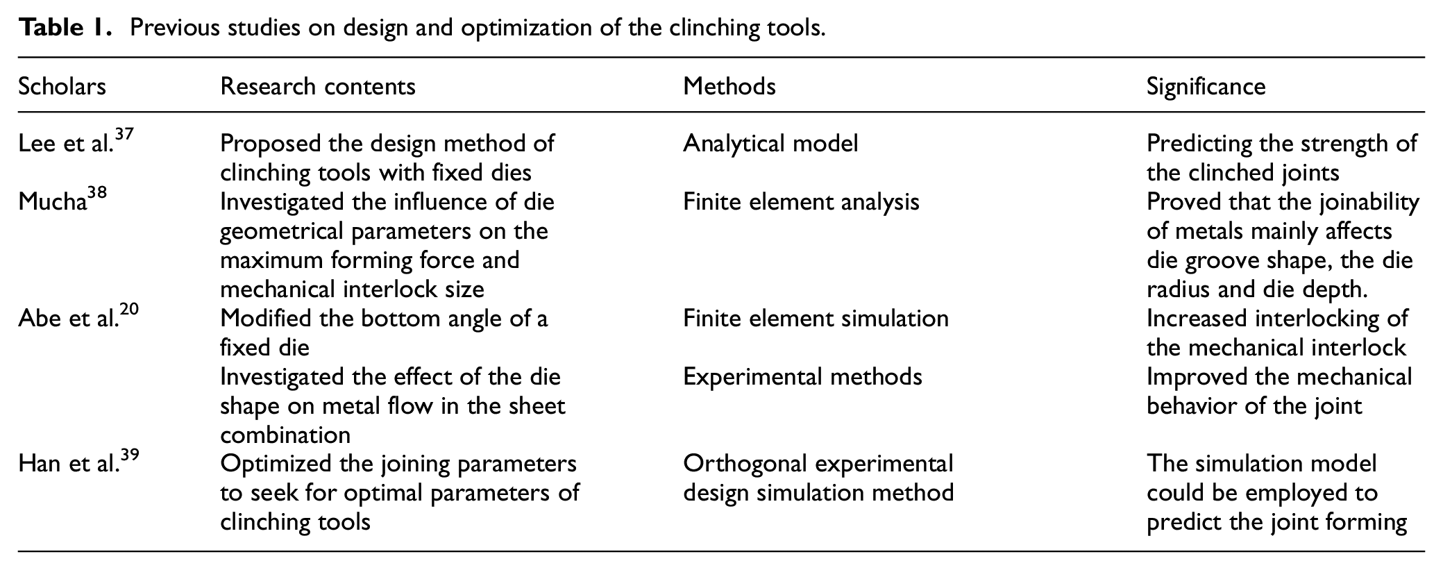
In order to analyze the effect of the clinching tool on mechanical properties of the joint, previous studies mostly concentrated on clinching process with the fixed dies by experiments and finite element modeling methods. Some previous work of authoritative scholars in design and optimization of the clinching tools are summarized in Table 1. The main difference from the conventional clinching process with a fixed die is represented by the possibility of the movable segments extending during the clinching process. 29 The mechanical behavior of a clinched joint depends particularly on the neck thickness, the interlock value, the exterior height, and final bottom thickness.13,35,36
Previous studies on design and optimization of the clinching tools.
However, to the knowledge of the authors, there is no relevant exploration about the effect of extensible dies structure on the joint performance of the aluminum alloy sheets in the existing literatures. In the present work, the clinched joints on AA5052 sheets were produced with extensible dies of 2, 3, and 4 movable segments and a fixed die by mechanical clinching method. After the clinching process, the static strength tests for the clinched joints were carried out. Finally, the static shear-tensile strength, energy absorption, the joint stiffness, and failure mode of the clinched joints with fixed die and extensible dies of 2, 3, and 4 movable segments were investigated by experimental method, and the type of dies which was the most conducive in automobile manufacturing industry was determined.
Materials and methods
Materials
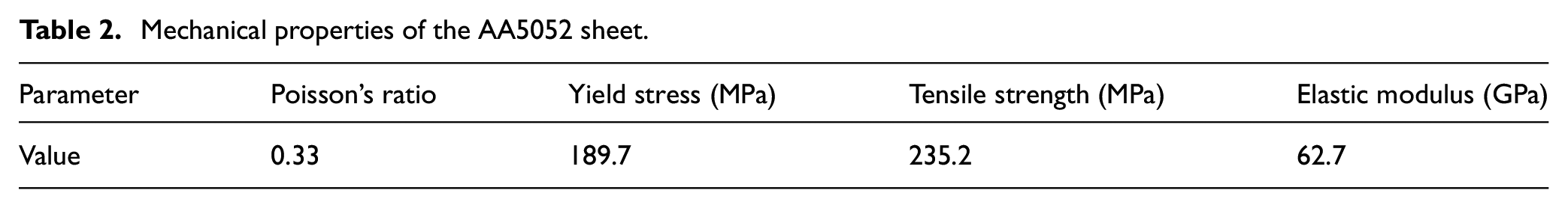
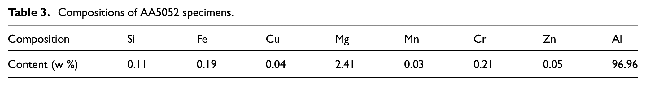
With the extensive application of lightweight materials in the automobile manufacturing industry, AA5052 is more and more favored by automobile manufacturers due to its excellent mechanical properties and great fatigue strength. 40 Therefore, the AA5052 sheet of 2 mm nominal thickness was used to produce clinched joints by mechanical clinching method in this study. The AA5052 specimens used for this experiment were cut into 80 × 25 mm (length × width) strips from a unique sheet. The mechanical properties of the specimens were tested on MTS 322 physical property testing machine. The testing results are presented in Table 2. The chemical compositions of AA5052 specimens used in this study are shown in Table 3.
Mechanical properties of the AA5052 sheet.
Compositions of AA5052 specimens.
Principle of mechanical clinching process
In the process of clinching aluminum alloy sheets, a pair of convex die and concave die is used to press the joining sheets. The plastic deformation ability of the metal is used to achieve the joining purpose by the mechanical interlock structure.41–43 As reported in Figure 1, the clinching system consists of the punch, blank holder, sliding sectors, rubber ring, and fixed die. During the clinching process, the punch and sliding sectors are movable, whereas the fixed die is fixed.
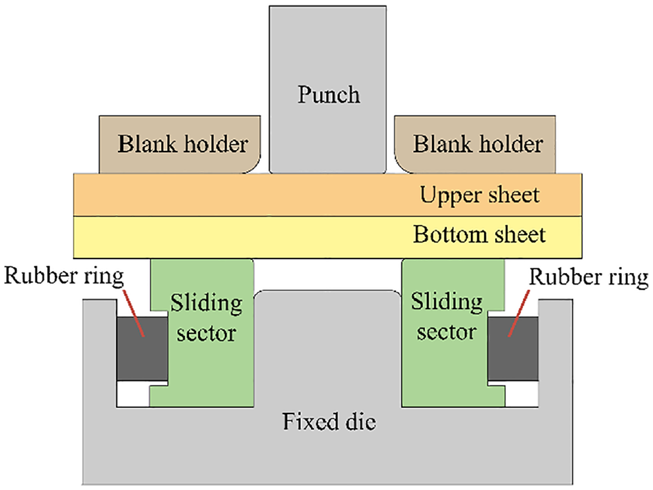
The clinching system with extensible die.
As depicted in Figure 2, the clinching process with extensible dies is divided into four phases, namely localized plastic deformation, drawing, radial material flowing, and interlock forming. 44 In the initial stage of mechanical clinching, the punch presses the upper sheet at a constant speed, and the upper sheet and lower sheet are plastically deformed at the same time. Then the AA5052 sheets are continued to undergo plastic deformation along the axial direction with the downward movement of the punch. When the lower sheets contact the surface of the fixed die, the sliding sectors expand in the radial direction of the fixed die as the sheet material flowed. Sliding sectors of the extensible dies are employed to make the material flow well-distributed in the radial direction, while the function of fixed die in the extensible die is to limit the material flow in the axial direction and determine the exterior protrusion height. With the moving downward of the punch, the sliding sectors moved radially until reached the limit position. When the load reaches the preset value, a mechanical interlock structure between the upper sheet and the lower sheet is generated, and the punch stops pressing down to form a clinched joint. At the end of the clinching process, the punch returns to the initial position at a constant speed, and the sliding sectors are also reset to the initial position under the action of the rubber ring.
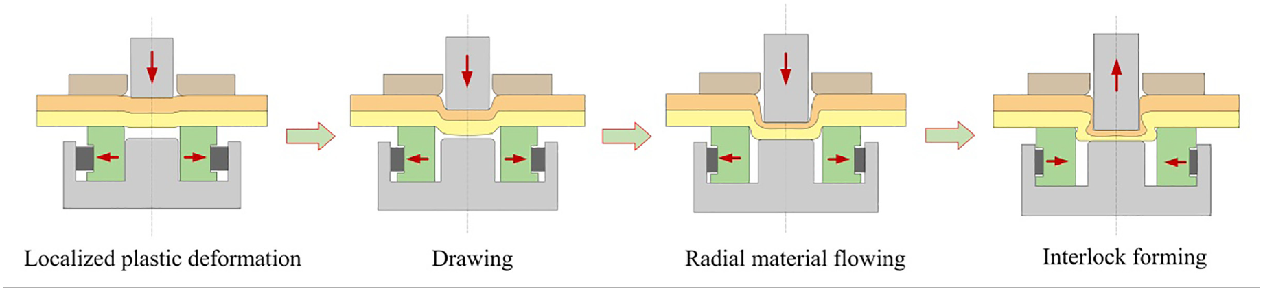
Phases of the clinching process with extensible dies.
In this study, a fixed die and the extensible dies with 2, 3, and 4 movable segments were employed to produce clinched joints. A series of preliminary tests were carried out to determine the optimum forming force: 30 kN. The mechanical properties of these joints were tested in cross-lap-tensile and single-lap-shear experiments to compare the joining effects of different dies. Figure 3 depicts dissimilar clinched joints produced by fixed dies and extensible dies.
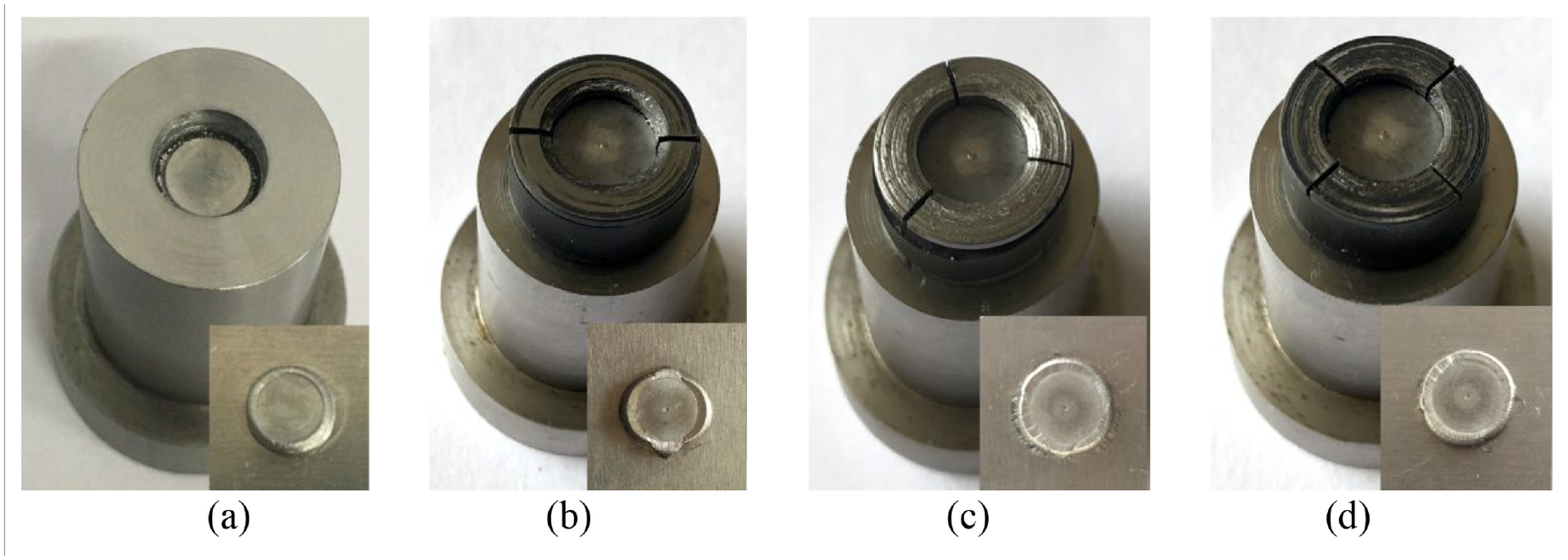
Clinched joints and dies: (a) fixed die, (b) extensible die with 2 movable segments, (c) extensible die with 3 movable segments, and (d) extensible die with 4 movable segments.
In order to facilitate the description of the clinched joints, the following terminologies are used to describe the different types of joints in this work:
CR-N: The clinched joint with fixed dies;
CR-2: The clinched joint with extensible dies of 2 movable segments;
CR-2-S: Cross-section of the ellipse CR-2 joint along the short axis (Figure 4(b));
CR-2-L: Cross-section of the ellipse CR-2 joint along the long axis (Figure 4(a));
CR-3: The clinched joint with extensible dies of 3 movable segments (Figure 4(c));
CR-4: The clinched joint with extensible dies of 4 movable segments (Figure 4(d)).
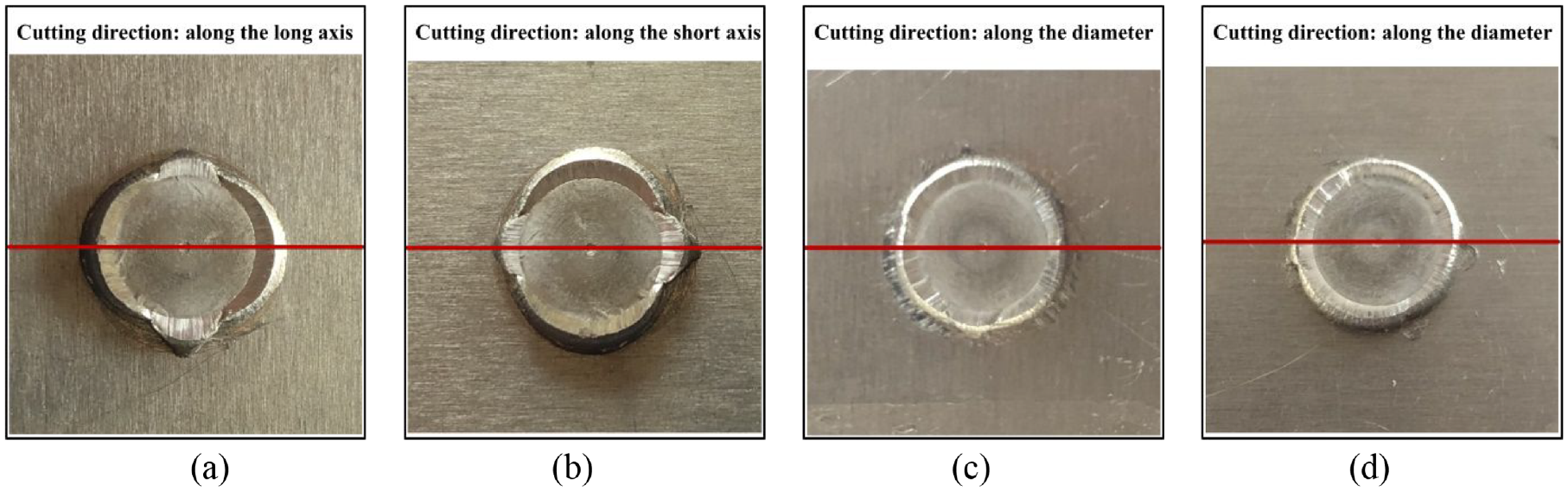
The cutting direction of clinched joint with different extensible dies: (a) CR-2-L, (b) CR-2-S, (c) CR-3, and (d) CR-4.
The process of forming evolution
The die structure is an important factor that affects the forming evolution of the joint. In the same forming process, different die structures produce different joint geometric parameters, which affect the mechanical performance of the clinched joint. Figure 5 depicts the joint forming evolution process with different dies in this study.
The joint forming evolution process with different dies.
As shown in Figure 5, the two AA5052 sheets were placed on the extensible die, and the punch with 5.5 mm diameter moved downward to compress the upper sheet under a precisely controlled velocity of 2 mm/min. After the processes of localized plastic deformation, drawing, radial material flowing, and interlock forming, the mechanical interlock structure gradually formed. When the forming force reached the preset load of 30 kN, the punch stopped moving down and moved upward at a constant speed of 4 mm/min to return to the initial position. At this point, the forming process is finished.
Static strength tests
The mechanical performance of the clinched joint is always evaluated by the cross-lap-tensile and single-lap-shear strength tests. In order to investigate the difference performance of the clinched joints produced by different dies, the fixed die and the extensible dies with 2, 3, 4 movable segments were employed in the clinching process for joining the AA5052 sheets in this study. The static strength tests were implemented on SUST CMT-5105GJ testing machine. The test velocity was 2 mm/min in this work. The load force, displacement, and velocity of the testing machine can be controlled precisely by the computer. The load-displacement curve and maximum loading force can be monitored and recorded by the testing system, and the maximum loading forces recorded in the single-lap-shear and cross-lap-tensile tests were regarded as the shearing strength and tensile strength of the clinched joints. The maximum loading force and the force-displacement curve can be obtained after the static strength tests. The specimens used for the static strength tests were shown in Figure 6.
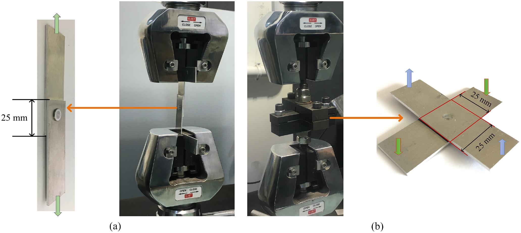
Specimens used for the static strength tests: (a) specimen used for single-lap-shear test and (b) specimen used for cross-lap-tensile strength test.
There is no chemical process in the whole mechanical clinching process, and clinched joints are produced by plastic deformation. The two sheets are connected by mechanical interlock structure.45–47 Therefore, the geometric characterizations of clinched joint have an important influence on the joint strength and energy absorption in the static strength test. The main geometric parameters of the clinched joint were indicated in Figure 7. In mechanical clinching process, the upper sheet undergoes an obvious thinning near the punch surface, and the mechanical properties of joints are particularly dependent on the neck thickness (tn), interlock (ts), bottom thickness (X), and exterior protrusion height (h). The height of the exterior protrusion (h) affects the application field and esthetics of the joints, while the neck thickness (tn) and the interlock value (ts) affect the failure mode and static strength of the clinched joint in the static strength test directly. As for the bottom thickness (X), it is a key reference for judging the mechanical forming condition without damaging the joint. It indirectly reflects the relationship between the neck thickness and the interlock value.
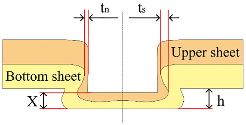
Geometric characterization of the joint profile.
Results for profile and static tests of joints
Geometric characterization of the joint profile
As presented in Figure 8, in order to visually compare the appearance differences of the joints made by a fixed die and different types of extensible dies, the cross-sectional view of the joints produced with fixed dies and the extensible dies are shown in a separate diagram. Since the cross-sectional shapes of the CR-2 joints cut along the long axis and the short axis are different, the profiles of the CR-2-L joints and the CR-2-S joints are compared with those of the CR-N joints respectively. The neck thickness (tn), interlock (ts), and exterior protrusion height (h) can be measured in the Figure 8.
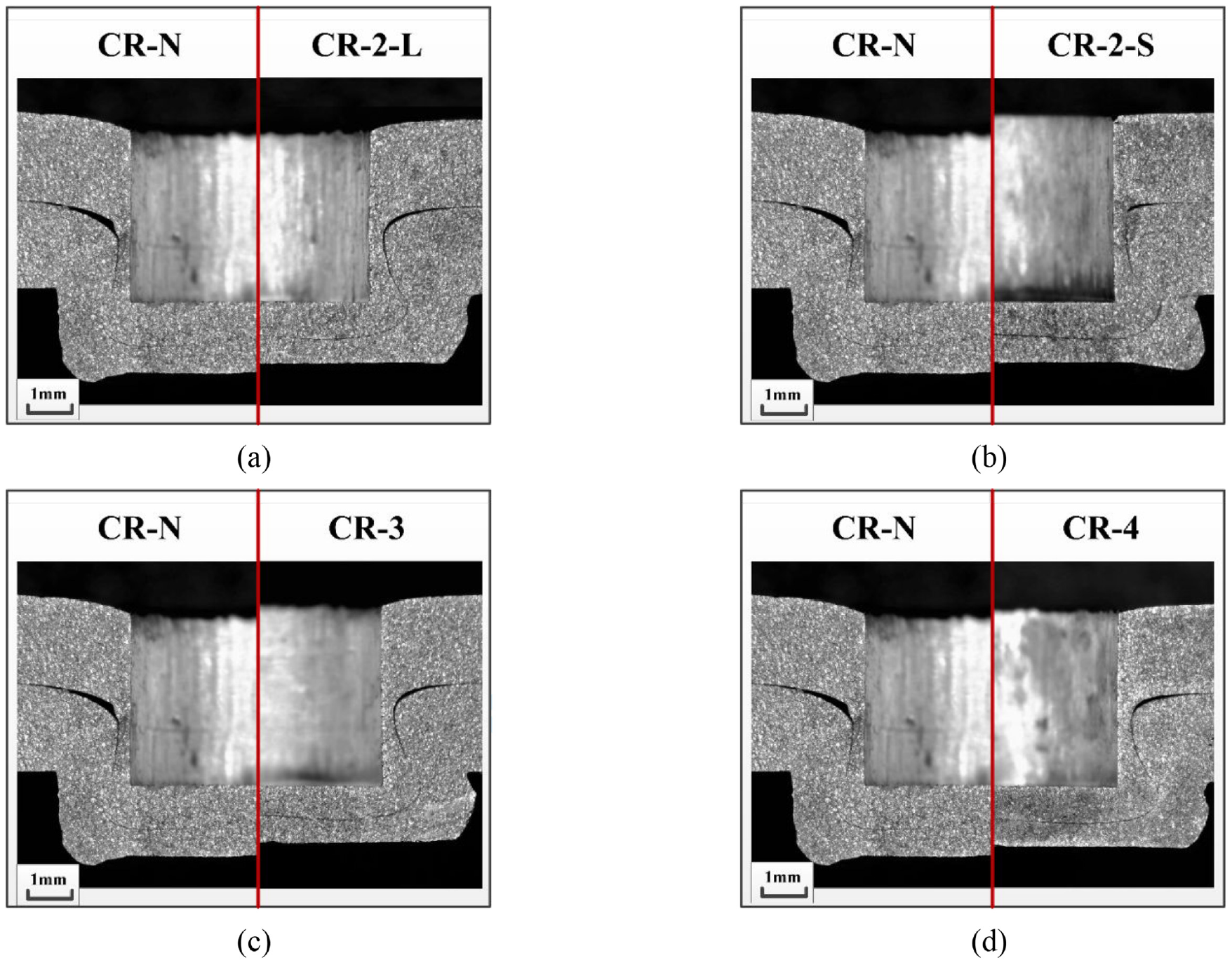
The cross-sectional comparison of CR-N joint with (a) CR-2-L joint, (b) CR-2-S joint, (c) CR-3 joint and (d) CR-4 joint, respectively.
As shown in Figure 9, the interlock values of all clinched joints produced by all dissimilar dies are higher than their neck thickness, which generates the neck fracture mode in the failure process. Although the neck thickness and interlock value of the joints made by the three kinds of extensible dies are larger than those made by the fixed die, the neck thickness and interlock amplitude of the three types of joints have little change in forming process. It can be seen from the error bar that the mechanical clinching process of the CR-3 joints is more stable.
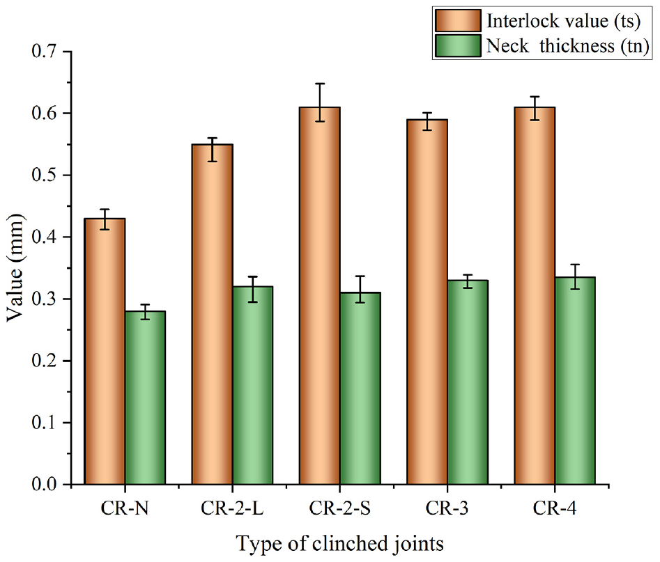
The measured values of interlock
Test results of static tests
The static strength of the clinched joints can generally be divided into tensile strength and shearing strength. Tensile strength usually refers to ability of clinched joint to resist axial tensile failure loads. Similarly, the definition of shearing strength is to the ability of clinched joint to resist radial shearing failure loads. In order to test and evaluate the strength of the joints produced by different dies, in this work, the single-lap-shear and cross-lap-tensile tests were conducted at room temperature. The test speed was 2 mm/min until two sheets completely separated. Three replicates static strength tests were conducted to each type of joint so as to ensure the accuracy of the experimental results, and the average value was taken as the main indicator of mechanical properties. For each test, the joint strength, failure mode, force versus displacement curves, the joint stiffness, and energy absorption were analyzed in this study.
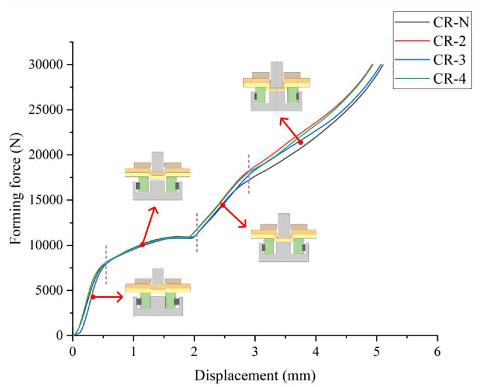
Figure 10 shows the force–displacement curves registered during the static strength tests on clinched joints with dissimilar dies, respectively. All the single–lap-shear load curves have the same tendency in the static strength test, and all the cross-lap-tensile load curves are also similar. Whether in the single-lap-shear test or cross-lap-tensile test, the joining strength of clinched joints produced by extensible dies is generally higher than that of fixed dies.
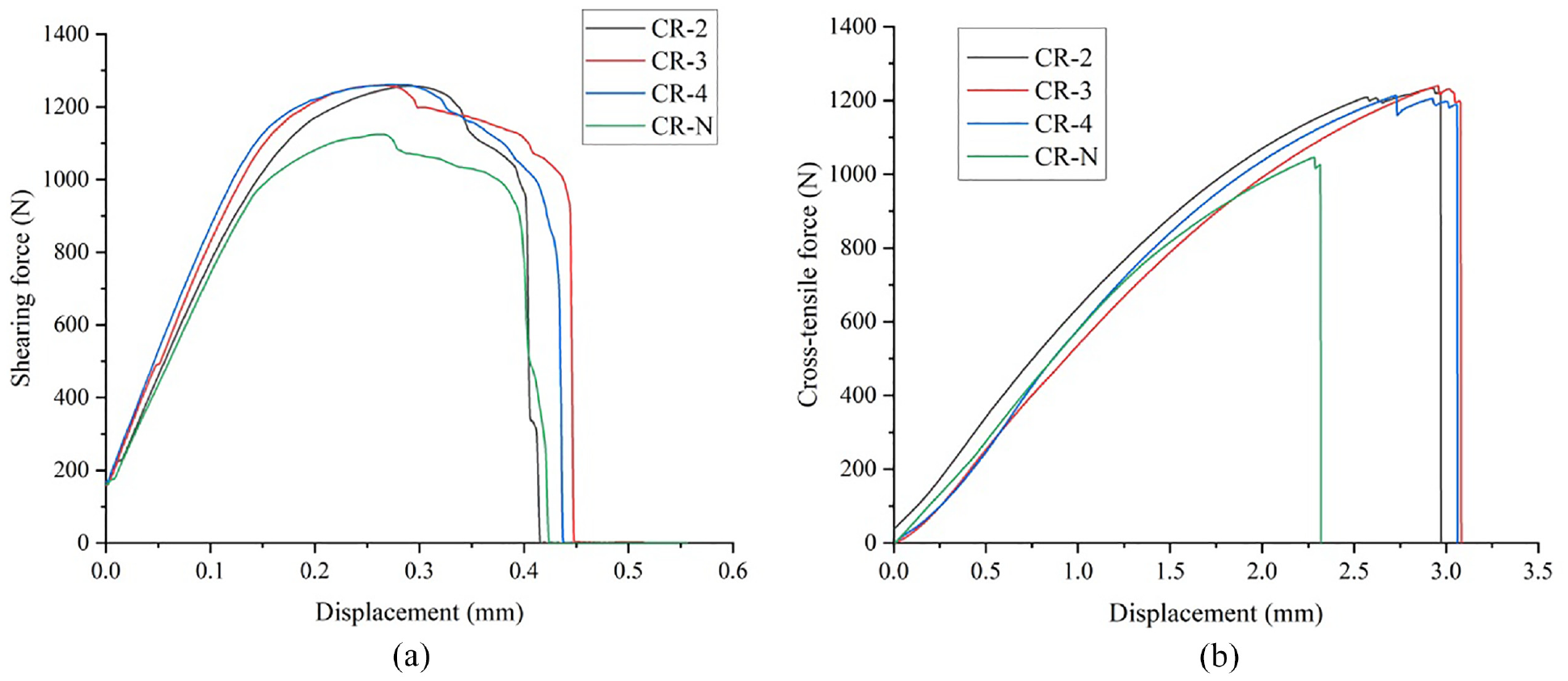
The typical force versus displacement of clinched joints in (a) single-lap-shear test and (b) cross-lap-tensile test.
As depicts in Figure 10(a), the whole process can be appreciated with different phases during the single-lap-shear test. Before the 0.18 mm shearing displacement of the clinched joints with extensible dies, it basically grows linearly with the increase of the load, which is caused by the plastic deformation of the material during the single-lap-shear test. However, the shearing displacement of the clinched joint with the fixed die is 0.15 mm. Figure 10(b) presents the load-displacement curves of dissimilar clinched joints in the cross-lap-tensile test. The tensile displacement of clinched joints produced by extensible dies in the plastic deformation phase of the test is 1.9 mm, which is more than 10 times the shearing displacement. The tensile displacement of clinched joints made by fixed dies is 1.2 mm in the plastic deformation phase.
Figure 11 illustrates the tensile strength and shearing strength of the clinched joints produced by dissimilar dies, which were carried out by three sets of single-lap-shear and cross-lap-tensile strength tests to get the accurate average strength for each configuration of the clinched joints.
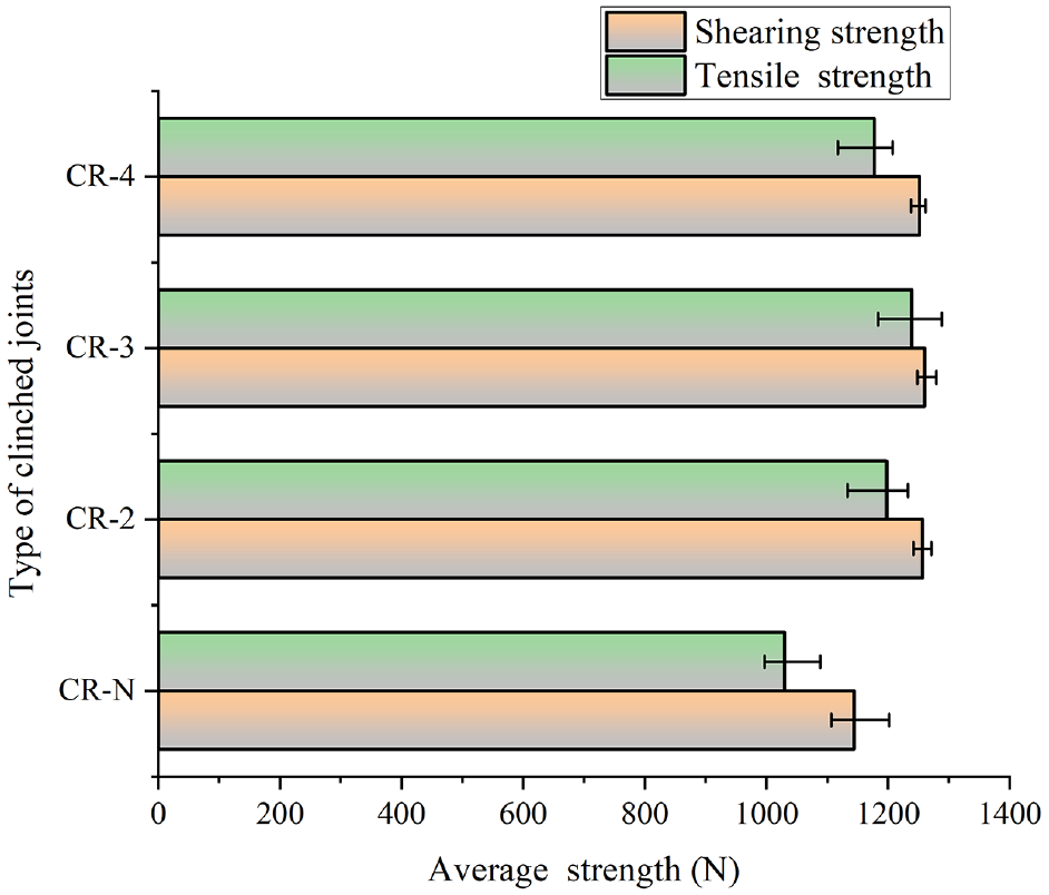
The tensile strength and shearing strength of the clinched joint with dissimilar dies.
To be precise, the sliding distance of the extensible die is influenced by friction and material flow in the mechanical clinching process. Under the same friction factor, a larger forming force increases the friction between the sliding part and the fixed die, and therefore the outward sliding distance of the sliding part would be affected to different degrees. It is assumed that the sliding distance of the sliding part is similar for different forming forces, that is, the effect of friction on the strength of the joint is ignored in this study.
In addition, forming process of mechanical interlock involves a large amount of material flow. The large material flow and plastic deformation in the clinched joint result in different hardnesses at different locations of the joint. 48 An increase in hardness leads to an increase in material strength, which can affect the process and outcome of joint failure. In this work, the effect of plastic deformation on the strength of the clinched joint was also ignored and the mechanical behavior law of the joint is explored directly from the geometry parameters of the mechanical interlock.
Failure mode
Neck fracture and button separation are two main failure modes for the clinched joints in the static strength tests.31,49,50 If the bottom part of the upper sheet is pulled out from the mechanical interlock during the strength test, the failure mode is button separation failure mode. If the thinnest region of the joint neck is fractured, the failure mode is referred to neck fracture failure mode.31,51,52
In this paper, all the failure modes of the clinched joints produced with dissimilar dies in the static strength tests were neck fracture (see Figure 12). This type of failure mode is mainly caused by insufficient neck strength compared with interlock strength. For neck fracture failure mode of the clinched joints, the interlocking value ts has little effect on the joint strength and energy absorption of the joints in the process of static strength tests, while the neck thickness value tn directly affects the shear-tensile strength and energy absorption of the joints.
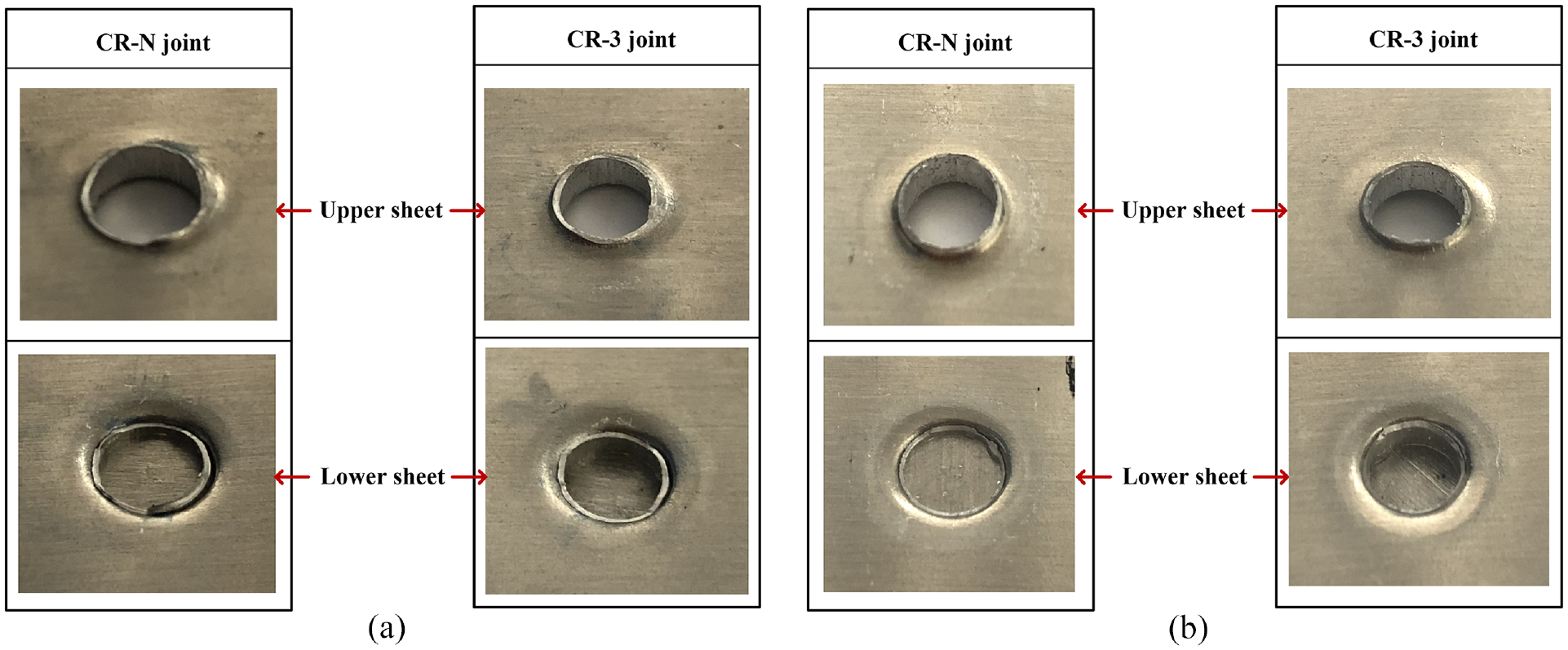
Damaged joints in static strength tests: (a) single-lap-shear test and (b) cross-lap-tensile test.
The joint stiffness and energy absorption
In the design of automobile structure, generally, when the stiffness of the structure around the hole or circular groove changes suddenly, it is easy to produce stress concentration at the position of the sudden change in stiffness, so that the crack occurs at the relatively weak corner of the hole or circular groove. The joint stiffness of the clinched sheets refers to the ability of the joint material to resist deformation and stretching, and it can also show the internal stress and strain distribution of the clinched joint.
As a stressed structure, the automobile body structure must not only ensure sufficient strength and certain stiffness K (as depicted in Figure 13) to meet its fatigue life and assembly requirements during the design and use processes, but also have sufficient energy absorption (EA) capacity to ensure the safety of passengers in a collision. 53 EA determines how much energy the joints can withstand before failure. Therefore, it can be said that clinched joints with high energy absorption have better performance under crash conditions. The EA can be determined by calculating the area between the x-coordinate and the force-displacement curve which is demonstrated in Figure 13.
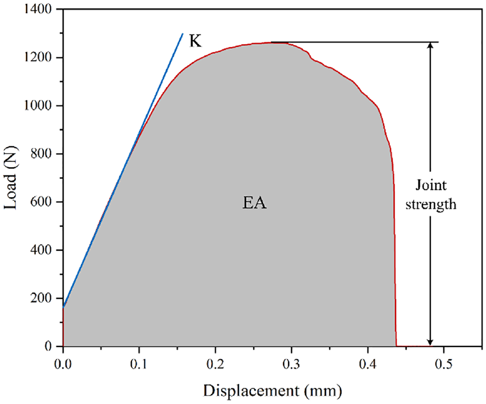
The mechanical behaviors tested in single-lap-shear test.
In addition, the average strength and stiffness of clinched joints were compared in cross-lap-tensile and single-lap-shear tests. It is interesting to note from Figure 14 that the variation of the joint strength produced by different types of dies is opposite to that of the joint stiffness in the cross-lap-tensile test. While in the single-lap-shear test the change of shearing stiffness is more obvious than tensile stiffness in the cross-lap-tensile test, and shearing stiffness is several times greater than the tensile stiffness. As shown in Figure 15, the stiffness difference in different static tests also indirectly causes the energy absorption value in the single-lap-shear test to be much larger than the energy absorption value in the cross-lap-tensile test. In other words, different clinched joints produced with dissimilar dies have strong resistance to elastic deformation during the single-lap-shear process, and the shearing stiffness values have large changes. In the cross-lap-tensile test, the above-mentioned joints have poor resistance to plastic deformation, and tensile stiffness of dissimilar joints is almost the same.
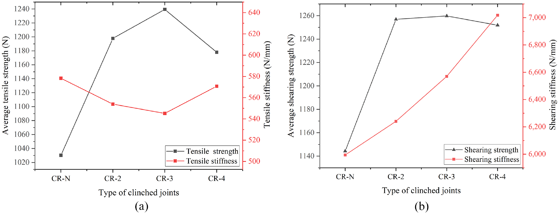
Average strength and stiffness of the joints in static strength tests: (a) tensile strength and stiffness and (b) shearing strength and stiffness.
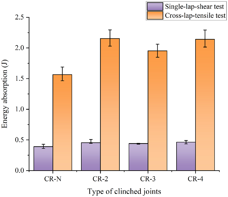
Energy absorption values in the single-lap-shear and cross-lap-tensile tests.
Discussion
In the field of industrial applications, there are many production methods for clinching joints. The utilization of extensible dies is beneficial to the uniform flow of materials during the clinching process and the demolding of the dies after the clinching process. In this paper, the mechanical properties of joints produced by fixed dies and extensible dies with different number of movable segments were investigated.
As depicted in Figure 5, there was no difference in the process of forming evolution for all extensible dies and fixed die. There was no crack and sheet material coherence loosing in the concave part of the clinched joint and exterior protrusion. The number of movable segments does not significantly affect the process of forming evolution.
The static strength of the dissimilar joints was also investigated and compared in this work. The test result shows that the failure mode of all the joints was neck fracture failure mode. Compared with the fixed dies, the clinched joints produced by extensible dies had the higher strength in the static strength tests, which had the more significant mechanical interlock with a shape of inverted “
In terms of joint stiffness performance, compared with the CR-N joint, CR-2 joint, and CR-4 joint, the CR-3 joint was more conducive to the uniform flow of sheet materials, the stiffness performance between the single-lap-shear test and cross-lap-tensile test was quite different. In the cross-lap-tensile test, the stiffness of various types of joints changed little, the stiffness of the CR-3 joint was the lowest (K = 545.18 N/mm), but its strength was the highest (1239.41 N). The CR-N joint had the highest stiffness (K = 578.26 N/mm) and the lowest strength (1030.24 N). In the single-lap-shear test, the stiffness of the joint produced by the fixed dies was the smallest (K = 5993.49 N/mm) and the lowest strength (1144.29 N), while the stiffness of the CR-4 joint was the largest (K = 7017.58 N/mm) which shearing strength was the lowest (1251.83 N) among three extensible dies.
In addition to the fact that the movable segment structure was conducive to the material flow and mechanical interlock formation in the joint forming process, another possible explanation was that the joint produced by a fixed die has higher stiffness, and the stress concentration of the upper sheet is more obvious, which promoted early crack development of the joint, and eventually resulted in the failure of the clinched joint produced by a fixed die in the static strength test. In addition, the extensible dies with 3 movable segments had lower requirements on the neutral of punch and bottom die. Compared with the extensible dies with 2 and 4 movable segments, better symmetry and smaller exterior protrusion height were reflected on the extensible dies with 3 movable segments. Therefore, when the extensible die was used for clinching process, the application of extensible die with 3 movable segments was relatively wide.
Conclusions
In this study, an experimental test was carried out to assess the main differences among clinched joints produced with different die configurations, including a fixed die and three different extensible dies. The AA5052 joints clinched by different dies were analyzed by static shear-tensile strength tests. In addition, geometric characterization, energy absorption, failure mode, and stiffness of different joints were performed to understand the different behaviors of the joints during the mechanical tests. The main conclusions of this paper can be summarized as follows:
In the same forming conditions, compared with the fixed die, utilizing the extensible dies not only contribute to the material flow and the formation of mechanical interlock in the forming process, but also increase 9.4%–10.09% of the shearing strength and 14.34%–20.31% of tensile strength effectively.
When the extensible die is used to produce the clinched joint, the number of the extensible dies movable segments has little effect on the tensile strength, the stiffness and energy absorption of the clinched joints in the cross-lap-tensile test, while it has great effect on the stiffness and energy absorption of the joints in the single-lap-shear test.
In the static strength tests, the shearing strength and tensile strength of the joints produced by extensible dies of 3 movable segments are 1259.8 and 1239.41 N, respectively. Shearing strength of the joints performed by the extensible dies with 2, 3, and 4 movable segments was increased by 9.84%, 10.09%, and 9.40%, and the tensile strength was increased by 16.27%, 20.31%, and 14.34% than that of the joints produced by the fixed dies.
The results show that the tensile stiffness of different types of clinched joints has little change when the dissimilar extensible dies are used for joining AA5052 sheets, but the number of movable segments of extensible dies has a great influence on the shear stiffness, and the stress concentration is partly responsible for the improvement of the joint stiffness, and it can promote the expansion of early cracks, thus accelerating the failure of the clinched joints.
Recommendations
Comparing the mechanical properties of the joints made by different dies, the great application prospect of the extensible die for clinched joints was demonstrated. In view of the current applications of the clinched of joints, and the problems and challenges during the period of service, the further study is to conduct the dynamic strength tests on clinched joints produced by different dies. The fatigue strength of the joints under dynamic load and the mechanical performance of the joints under impact load should be analyzed to evaluate the advantages and disadvantages of different dies in a more comprehensive way. In addition, joining dissimilar materials, especially those with a large difference in ductility, is still a challenge. Therefore, it is a more promising solution that considering increasing the material fluidity of the joined sheets and optimizing the parameters and structure of the clinching tools.
Footnotes
Declaration of conflicting interests
The author(s) declared no potential conflicts of interest with respect to the research, authorship, and/or publication of this article.
Funding
The author(s) disclosed receipt of the following financial support for the research, authorship, and/or publication of this article: This research work is supported by the National Natural Science Foundation of China (Grant No. 51805416), Young Elite Scientists Sponsorship Program by CAST (Grant No. 2019QN RC001), Hunan Provincial Natural Science Foundation for Excellent Young Scholars (Grant No. 2021JJ20059), and Huxiang High-Level Talent Gathering Project of Hunan Province (Grant No. 2019 RS1002).