
Abstract
The present study aimed to implement a sustainable machining method to improve energy efficiency in helical milling (HM) of AISI 1020. Therefore, ultrasonic vibration is integrated with conventional helical milling to reduce cutting forces. A model was developed for power consumption in terms of cutting forces in x, y and z directions, tangential and axial feed speeds. Series of plain and ultrasonic vibration helical milling (UVHM) experiments are conducted using 10 and 8 mm diameter mill cutters at different working conditions and experimental results for cutting forces are collected. Formation of chip and its geometry are investigated using the cutting trajectories of the bottom cutting edges of the cutter. Cutting forces and power consumption are estimated related to chip geometry in plain and UVHM processes and compared. In UVHM, the axial force is reduced by around 47% as the ultrasonic vibration is applied in the axial direction and the power consumption is reduced by 34%. The results showed that ultrasonic vibration has a significant effect on chip morphology, cutting force and power consumption, indicating that ultrasonic vibration assisted machining has a wide application in manufacturing. The process parameters are optimised as 2000 rpm of cutter rotational speed, 156 rpm of cutter orbital speed and 0.3 mm of axial depth of cut using 8 mm diameter cutter and the chip thickness, chip depth and power consumption are found to be 0.3969 mm, 0.2665 mm and 835.6 W respectively at optimal working condition.
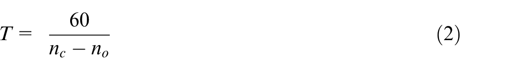
Introduction
AISI 1020 is a hot rolled plain carbon steel that has good machinability used in making motor shafts, motor brake wheels, seat brackets, gear drives, light gear, worm gears, axles, crane cable drums, ratchets used in agricultural, automotive and trucks. Since the metal has significant importance in manufacturing, the production cost should be reduced by reducing power consumption. Helical milling (HM) is an eco-friendly hole drilling process that is considered an emerging technology when compared with the conventional drilling process. In HM, a rotating mill cutter moves in a helical path to enlarge the hole diameter. Qin et al. 1 stated that the bottom cutting edge and peripheral cutting edges perform continuous and non-continuous cutting respectively in HM. Zhao et al. 2 found reduced cutting forces and tool wear with better dimensional accuracy in HM when compared with conventional hole-making processes. Ultrasonic vibration (UV) is introduced in HM to improve dimensional accuracy at reduced cutting forces and tooling cost. In ultrasonic vibration helical milling (UVHM), the cutting tool or workpiece is vibrated vertically with a frequency of more than 20 kHz which generates a discontinuous contact between bottom cutting edge and the workpiece further which results in reduced cutting force. 3 In another study, Chen et al. 4 found improved dimensional accuracy in UVHM when compared to plain HM. Therefore, the present study has proposed a detailed comparative study on cutting forces and power consumption concerning chip geometry at different working conditions for both plain and UVHM.
Power consumption in machining is directly affected by cutting forces which increases the production cost.5,6 Jamil et al. 7 stated that the sustainable manufacturing minimises power consumption, emissions and environmental damage. Shang et al. 8 developed cutting force models and predicted the cutting forces using cutting force coefficients in HM, also found optimum working conditions for minimum cutting forces. Fu et al. 9 developed a mathematical model and predicted the cutting forces considering cutting and tool parameters in HM of Ti-6Al-4V. Yu et al. 10 stated that the cutting and thrust forces depend on shear force components and ploughing force components in three directions. Feng et al. 11 developed a three-degree-of-freedom dynamical system model and predicted the cutting forces in UV assisted drilling of TiBw/TC4 composite. Guo et al. 12 developed a mechanistic model using force coefficients and predicted cutting forces during side milling. Haiyan et al. 13 developed mechanistic models and estimated cutting forces using cutting force coefficients in HM of carbon fibre–reinforced plastics that are used in aerospace applications. But, these studies did not focus on reduction of cutting forces and power consumption.
Verma and Pandey 14 stated that ultrasonic vibration-assisted machining (UVAM) is one of the advancements in HM to reduce cutting forces in milling due to intermittent action of a cutting tool. Xu and Zhang 15 reported the UVAM applies micro scale high-frequency vibration to the tool or workpiece during the machining process to improve the performance of machining process. Tan et al. 16 used ultrasonic elliptical vibration assisted cutting in turning of Ti-6Al-4V and reduced cutting and frictional forces, also improved surface quality and tool life. Ning and Cong 17 made a review on outcomes of the UVAM for different metals and concluded that UVAM reduced cutting forces, tool wear and surface roughness. Gholamzadeh and Soleimanimehr 18 studied the effect of UV on machining and found that the assistance of UV reduced cutting forces and surface roughness. Ishida et al. 19 applied cryogenic tool cooling in the UVHM of carbon fibre reinforced polymer and reduced cutting forces with improved dimensional accuracy. Chen et al. 3 made a comparative study for plain and UVHM of Ti-6Al-4V alloy taking into account the formation of chips and cutting force and found a 38% reduction in axial forces in UVHM. However, this type studies have not concentrated on the reduction of cutting forces and power consumption in HM.
Optimisation of process parameters is considered as one of the most important energy saving technologies in metal cutting. 20 Optimisation techniques like Taguchi, response surface methodology (RSM), and grey relation analysis were used in manufacturing and reduced cutting forces and power consumption.21,22 Artificial neural networks and the Edgeworth-Pareto method were used in face milling and improved the machining performance. 23 Novel and hybrid optimisations techniques like simulated annealing, metaheuristic optimisation algorithms, Henry gas solubility optimisation algorithm, butterfly optimisation algorithm, equilibrium optimisation algorithm, sine-cosine optimisation algorithm and seagull optimisation algorithm are used and solved many complex engineering and manufacturing problems.24–35
In the existing research, the power consumption was measured with a wattmeter and analysed the effect of process parameters on the power consumption. But, the power is consumed by the production (metal cutting) and non-production (coolant pump, control system, automatic tool changer and pneumatic system, etc.) activities. Since the power consumed by the non-production activities cannot be reduced, the present study aimed to reduce power consumption by reducing the cutting forces. It is also summarised that formation of chip and chip geometry in the UVHM was not described clearly. Therefore, the present study is aimed to estimate power consumption considering cutting forces and chip geometry and the process parameters are also optimised to minimise power consumption for UVHM of AISI 1020. The present work is carried out in different stages. In stage 1, the trajectory of cutting edge is described, UVHM setup and experimentation is shown in section 3, estimation of cutting forces and power consumption at 30°, 60° and 90° of cutter rotation during the chip removal is described in section 4, process parameters are optimised in section 5 and the results are discussed and compared in section 6.
Trajectory of cutting edge in HM
Kinematics of HM
A special mill cutter is used in HM and its relative motion with the workpiece is composed of rotation of cutter about its axis, moving of rotary tool in a helical path around axis of hole and axial movement. As shown in Figure 1(a), nc is the cutter rotational speed, no is the cutter orbital speed and da is the axial depth of cut. Diameter of a hole after machining is estimated using the equation (1) 1

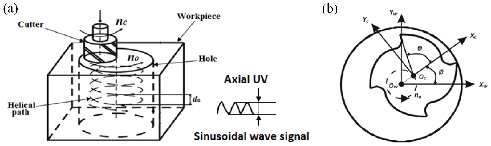
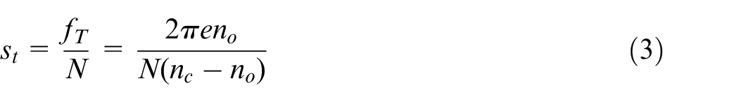
As shown in Figure 1(b) The workpiece coordinate system with the origin of OW is fixed around which the tool coordinate system having Oc as origin rotates with an angle of Θ and moves in a helical path with an angle of Ø. Hence, the feed per tooth is estimated using the equations (2–4). 8

Trajectory of cutting edge in UVHM
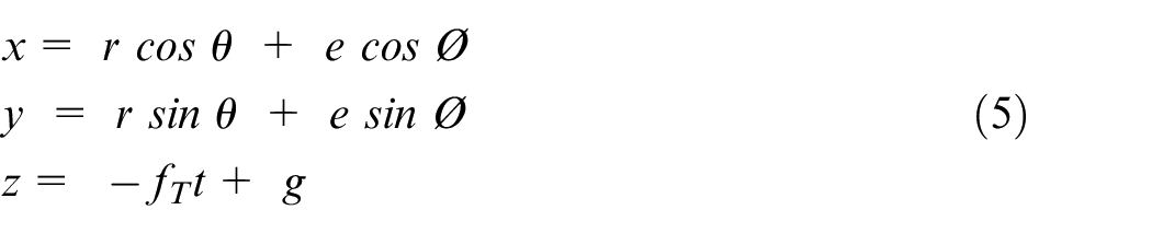
In the present study, four fluted mill cutter is used which consists of four cutting edges at the bottom such as O1A1, O1B1, O1C1 and O1D1. As shown in Figure 2, the A1 is considered as a point of the mill cutter on the XY plane. The cutting edge O1A1 rotates with an angle of Θ and moves around the axis of a workpiece with an angle of Ø to workpiece coordinate system. Then, coordinates of the point A1 is defined as follows 3
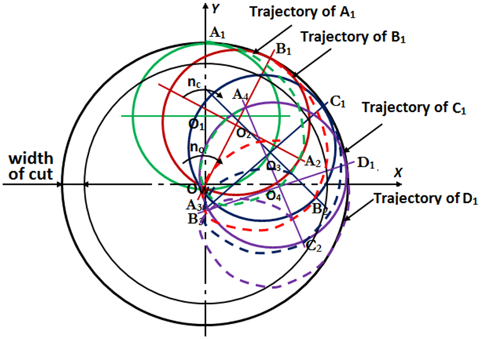
Trajectory of bottom cutting edges.
where g is the position of point A1 along the z axis. As shown in Figure 1, the workpiece is vibrated in axial direction with a specified frequency and amplitude. Then, the coordinates of the point A1 are defined as follows 3
When the cutter rotates 90°, centre of the cutter moves from O1 to O2 in orbital path and the cutting edge O1A1 is shifted to O2A2. Similarly, the cutter moves from O2 to O3, O3 to O4 and so on in orbital path. As the axial movement of each cutting point is identical, the bottom cutting edge generates an arc texture of A1, A2, A3, A4 and so on. Remaining cutting edges O1B1, O1C1 and O1D1 generate their paths as B1, B2, B3, B4 and so on, C1, C2, C3, C4 and so on and D1, D2, D3, D4 and so on respectively. The position of point A1 with respect to workpiece coordinate system is defined as follows:
Modelling of chip geometry
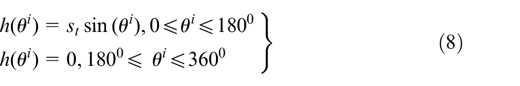
At starting of the machining, first chip is produced by the bottom cutting edge which is shown with enlarged size in Figure 3. After that, remaining chips are produced by the bottom cutting edge and peripheral cutting edges. Chip geometry produced by ith tooth defined by b(Θi) and h(Θi) as depth and thickness of chip respectively at Θi. Thickness of chip in HM is estimated using equation (8) and the depth of chip for plain and UVHM is estimated using the equations (9) and (10) respectively. 8
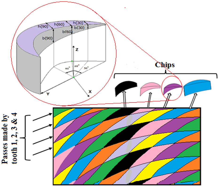
Formation of chips in HM.
In the present study, depth and thickness of chip are estimated at 30°, 60° and 90° of cutter rotation for plain and UVHM. The calculated chip geometry is used in estimation of cutting forces.
Modelling of cutting forces and power consumption
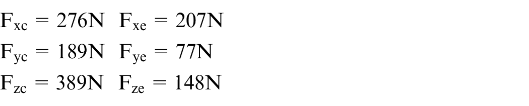
The cutting forces in machining process are estimated with chip geometry, shearing and ploughing forces. 36 Figure 4 shows cutting forces applied in the three directions during the HM. The cutting forces in the three directions are estimated as sum of shear force and ploughing force components.37,38 The cutting forces are estimated in three stages. In stage 1, shear force components (Fxc, Fyc and Fzc) and ploughing force components (Fxe, Fye and Fze) are estimated using zero uncut chip thickness method. 39 In the second stage, cutting force coefficients are estimated with force components and process parameters using equations (14) and (15). 40 In the third stage, cutting forces are estimated as per the chip geometry corresponding to 30°, 60° and 90° of cutter rotation using the equations (11)–(13). 37


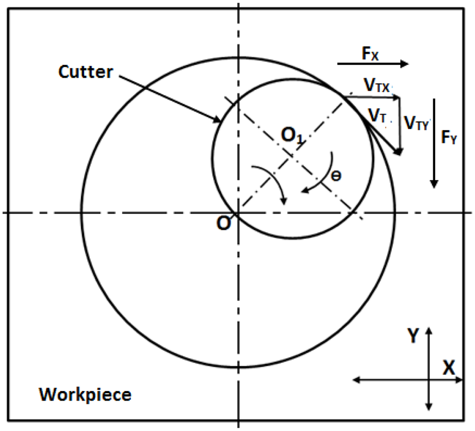
Cutting forces at cutter tooth.
Precise estimation of cutting force coefficients is important in the precise estimation of cutting forces. 39 The force coefficients are determined as follows 36
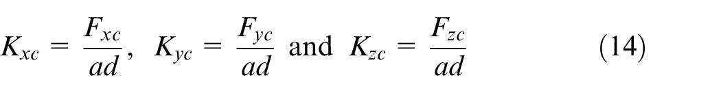
Where a is uncut chip thickness (mm) and d is the depth of cut (mm/rev) (also called axial depth of cut = da).
During the machining process, energy is consumed by different cutting and non-cutting activities. 41 The non-cutting activities include a coolant system, automatic tool changer, machine loading and unloading system and machine control system. However, it is not possible to reduce energy consumed by non-cutting activities. Whereas the power consumed by cutting activities is large. 42 Therefore, the power consumed by the cutting forces is estimated in the present study. Figure 4 shows cutting forces and cutting velocities in XOY plane and the power consumption (P) is estimated using the equation (16) in plain and UVHM and presented in Table 3.


Experimentation
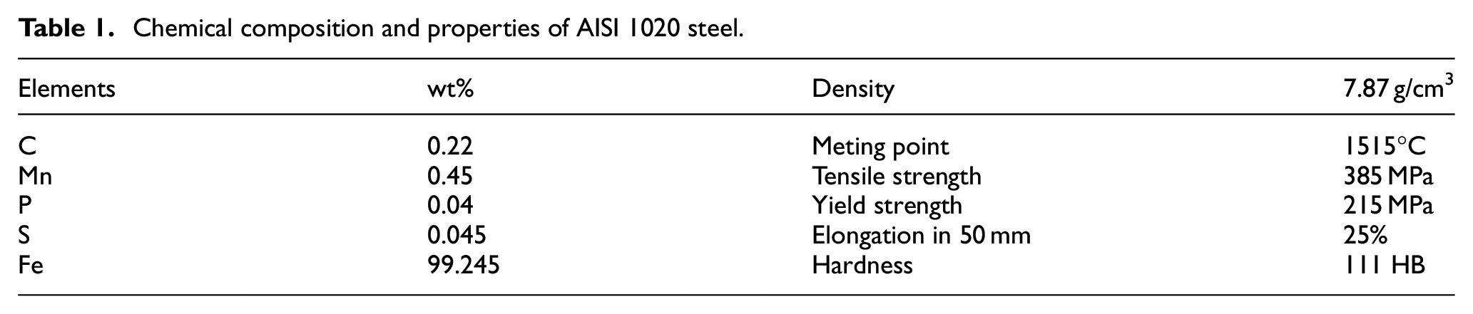
Experiments have been carried out on the proposed AISI 1020 steel using coated cemented carbide end mill cutters at different working conditions. Chemical composition and mechanical properties of the AISI 1020 steel are presented in Table 1.
Chemical composition and properties of AISI 1020 steel.
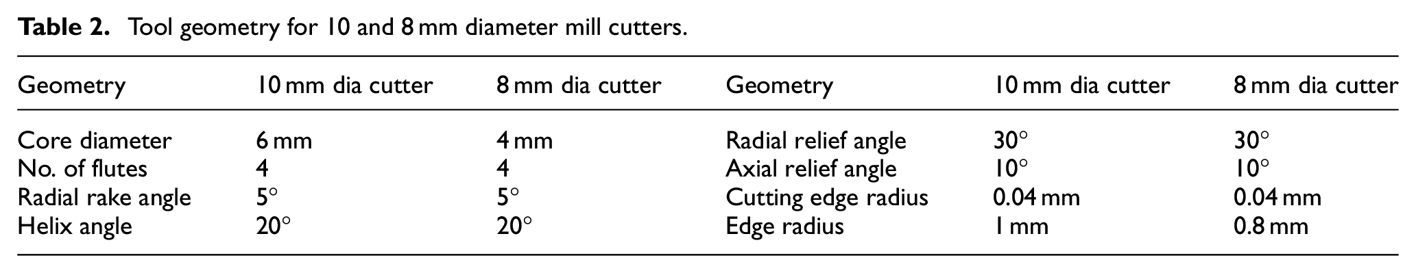
In the present study, a special mill cutter is used which consists of peripheral and end cutting edges. The end cutting edge is made of two parts for a better metal removal rate. There are two mill cutters with 10 and 8 mm diameters used in this study. Tool geometry for the mill cutters is presented in Table 2. The mill cutters used in the present study are shown in Figure 5
Tool geometry for 10 and 8 mm diameter mill cutters.
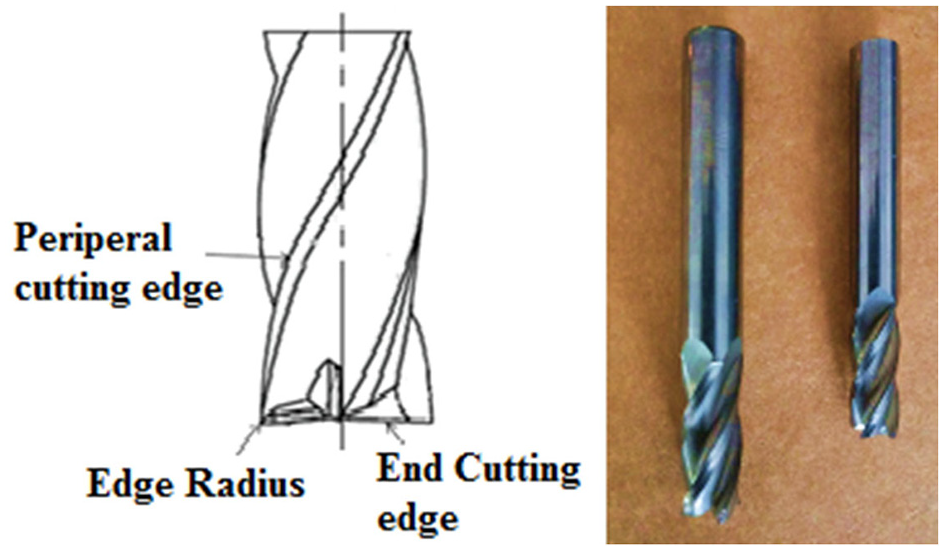
End mill cutters with 10 and 8 mm diameter.
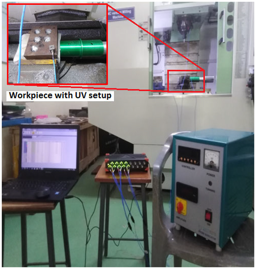
As shown in Figure 6, an experimental setup is prepared on a DMC-75V linear three-axis CNC vertical machining centre with 950 × 650 mm of table size. A Sonotrode of the UV source is held under the workpiece and the workpiece is vibrated in z direction (because axial depth of cut is given in the Z direction) with a frequency of 20 kHz. A KISTLER 9257B type force dynamometer is kept under work locating device to measure cutting forces in x, y and z directions. Before the experimentation, a hole is made on the workpiece with a diameter of 25 mm by the drilling process. As shown in Figures 1 and 4, the helical milling is performed at different working conditions. As per mixed level design of experiments, experimental plan is prepared with two levels of drill diameter, spindle rotational speed, axial depth of cut and four levels of orbital speed as presented in Table 3. During the experimentation, the hole size is enlarged to 26 mm diameter. The following experimental procedure is followed:
Sixteen experiments are carried on AISI 1020 steel as per experimental plan presented in Table 3. In each experiment, new tool is used and the spindle rotational speed, orbital speed and axial depth of cut are changed accordingly.
The workpiece is vibrated with a frequency of 20 kHz and amplitude of 5 µm in z direction during the experimentation.
Cutting forces in x, y and z directions are measured simultaneously using the dynamometer and presented in Table 3. The cutting forces are measured at starting, middle and end of the cutting and an average value was taken as reading. Each experiment is repeated twice and the error between the two experiments was found less than 5%.
Experimental setup for HM.
Experimental results of cutting forces in UVHM and plain HM.
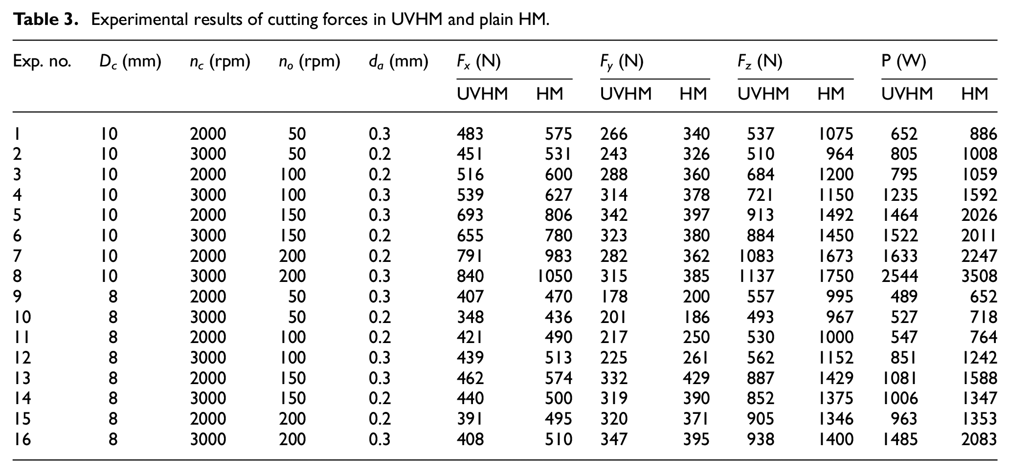
The same experimental procedure is performed on the same metal without ultrasonic vibration and experimental results of cutting forces are collected and presented in Table 3.
Estimation of chip geometry, cutting forces and power consumption
In the present study, chip geometry, cutting forces and power consumption are estimated and analysed in plain and UVHM. Detailed estimation and analysis are presented in the following sections.
Determination of chip geometry and analysis
During the UVHM, the formation of a chip is explained in section 2.3. Chip geometry such as thickness and depth of chip at 30°, 60° and 90°of cutter rotation is estimated using the equations (8) and (10) respectively. Similarly, chip geometry is also estimated for plain HM using the same equations (8) and (9).
It is observed that there is no variance in chip thickness between the plain and UVHM, but there is a difference in the chip height between the two processes. Figure 7 shows the comparison of chip depth in plain and UVHM processes. As the workpiece is vibrated in z direction, height of the chip is found more in UVHM. Though the amplitude of vibration is 5 µm, height of the chip is increased with an amount three to five times the applied vibration amplitude. During the HM, the workpiece material is subjected to compressive residual stresses in both circumferential and axial directions due to plastic deformation of metal. 2 Besides, the residual stresses in UVHM are found larger than residual stresses in the HM. 3 As the UV generates impulsive sinusoidal tool trajectory, axial movement of the cutting edge causes excess plastic deformation of material in an axial direction. Hence, depth or height of the chip is found larger than that of HM.
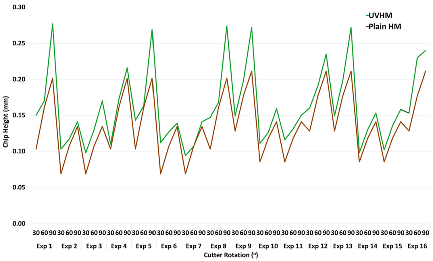
Chip height at 30°, 60° and 90° of cutter rotation.
Determination of cutting forces and analysis
As described in section 2.4, the cutting forces are estimated in three stages, such as estimation of force components, force coefficients and cutting forces.
Estimation of force components
In the estimation of cutting force coefficients, cutting or shear force components and end or ploughing force components are estimated. Figure 8 shows cutting and end force components in xand ydirections. The force components are estimated using zero uncut chip thickness method 37 for experiment 1 in UVHM as given below:
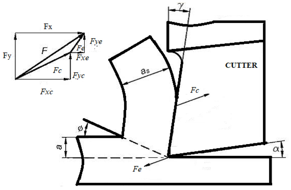
Cutting force components involved in machining.
Cutting force coefficients are estimated in x, y and z directions as given below:
Estimation of cutting forces and power consumption for UVHM and analysis
In this section, cutting forces in the three directions are estimated as the chip geometry changes. Equations (11) to (13) are used to estimate cutting forces in x, y and z directions corresponding to the chip geometry at 30°, 60° and 90° of cutter rotation for the 16 experiments. A sample calculation of cutting forces for experiment 1 is presented below:
Power consumption for the 16 experiments is estimated at 30°, 60° and 90° of cutter rotation using the equation (16) for the UVHM and plain HM. A comparison between the UVHM and plain HM for forces and power consumption is shown in the Figures 10 to 13.
Optimisation
In the present study, the process parameters are optimised for maximisation of chip thickness and its width and minimisation of power consumption using the RSM. The RSM is a statistical modelling technique that establishes a relationship between output characteristics and input parameters. 43 A quantitative relationship between input parameters and output characteristics is established as presented in equation (20). 44

As shown in Figure 9, the optimum values of cutter diameter, cutter rotational speed, cutter orbital speed and axial depth of cut for multi-objective power consumption, chip thickness and width are selected using MINITAB 17. Optimum parameters are found as 2000 rpm of cutter rotational speed, 156 rpm of cutter orbital speed and 0.3 mm of axial depth of cut using an 8 mm diameter cutter. The desirability function estimates the desirability of the responses using a gradient algorithm related to object of outputs. If the desirability of the response is close to 0, it is not accepted and if it is 1 or close to 1, it is accepted. 44 In the present study, the desirability values are estimated as 0.88505, 0.94358, 0.92912 for the power consumption, chip thickness and width respectively and the composite desirability is found as 0.9221. Hence, the optimisation is accepted. At the optimal working condition, an experiment is conducted twice and the experimental results of power consumption and chip geometry are compared with RSM predicted values. A good agreement is found between them with an average error of 4.36%, 2.51% and 3.92% for power consumption, chip thickness and depth respectively.
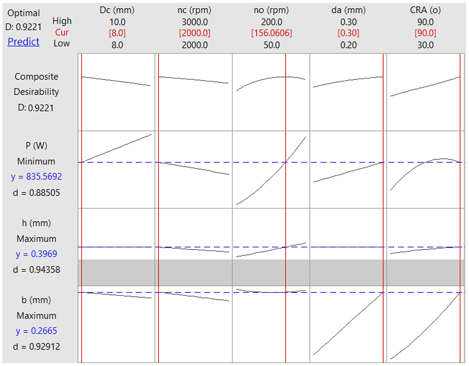
Multi response optimisation of process parameters.
Results and discussion
A comparison of forces in three directions between plain and UVHM and effect of process parameters on the cutting forces and power consumption are presented in this section. The cutting forces in the three directions increased as the tangential and axial feed increased, but the influence of the cutting speed on the forces is found less in plain and UVHM. Figures 10 and 11 are showing the variation in Fx and Fy respectively in XY plane. As shown in Figure 3, thickness of the chip increased as the cutter bottom tooth rotates from 0° to 90° and reduces till the tooth leaves the workpiece, but the height of the chip increases till the tooth leaves the workpiece. 9 As the chip thickness is increased from 0° to 90°, the cutting forces in xand ydirections increased in plain and UVHM. As shown in Figures 10 to 12, the forces in z direction are found to be larger than those of forces in xand ydirections. According to Bahi et al., 45 the resultant cutting force in XY plane is caused by bottom cutting edges and the axial force Fx is caused by bottom cutting edges and peripheral cutting edges. Hence, the force in z direction is found larger than the forces in xand ydirections. Among the spindle rotational speed, orbital speed and the axial depth of cut, the orbital speed (feed) has a significant effect on the cutting forces and power consumption and followed by the axial depth of cut and spindle rotational speed. As the orbital speed increased, size of the deformation zone increased which caused increased chip geometry as shown in Figure 7. Therefore, the plastic deformation of the metal increased the cutting forces in three directions; increased axial depth also caused additional plastic deformation, resulting in an increase of the cutting forces in the z direction.
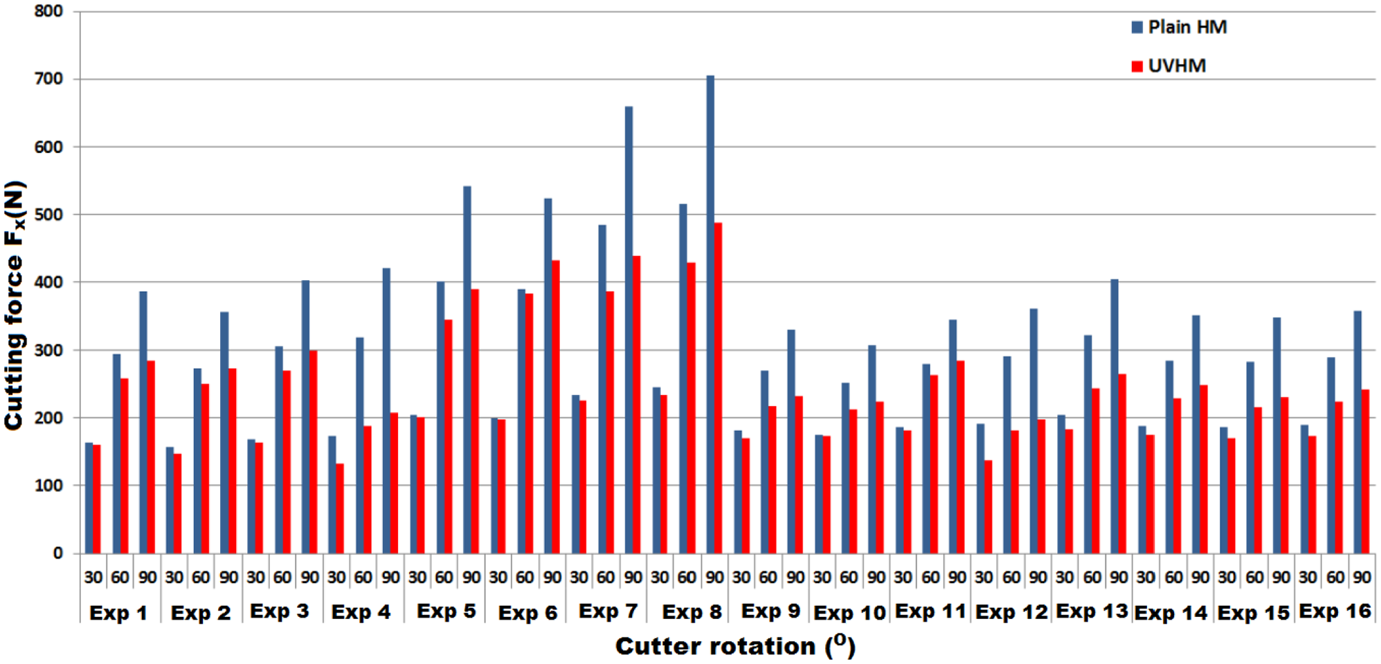
Cutting forces in x direction for plain and UVM.
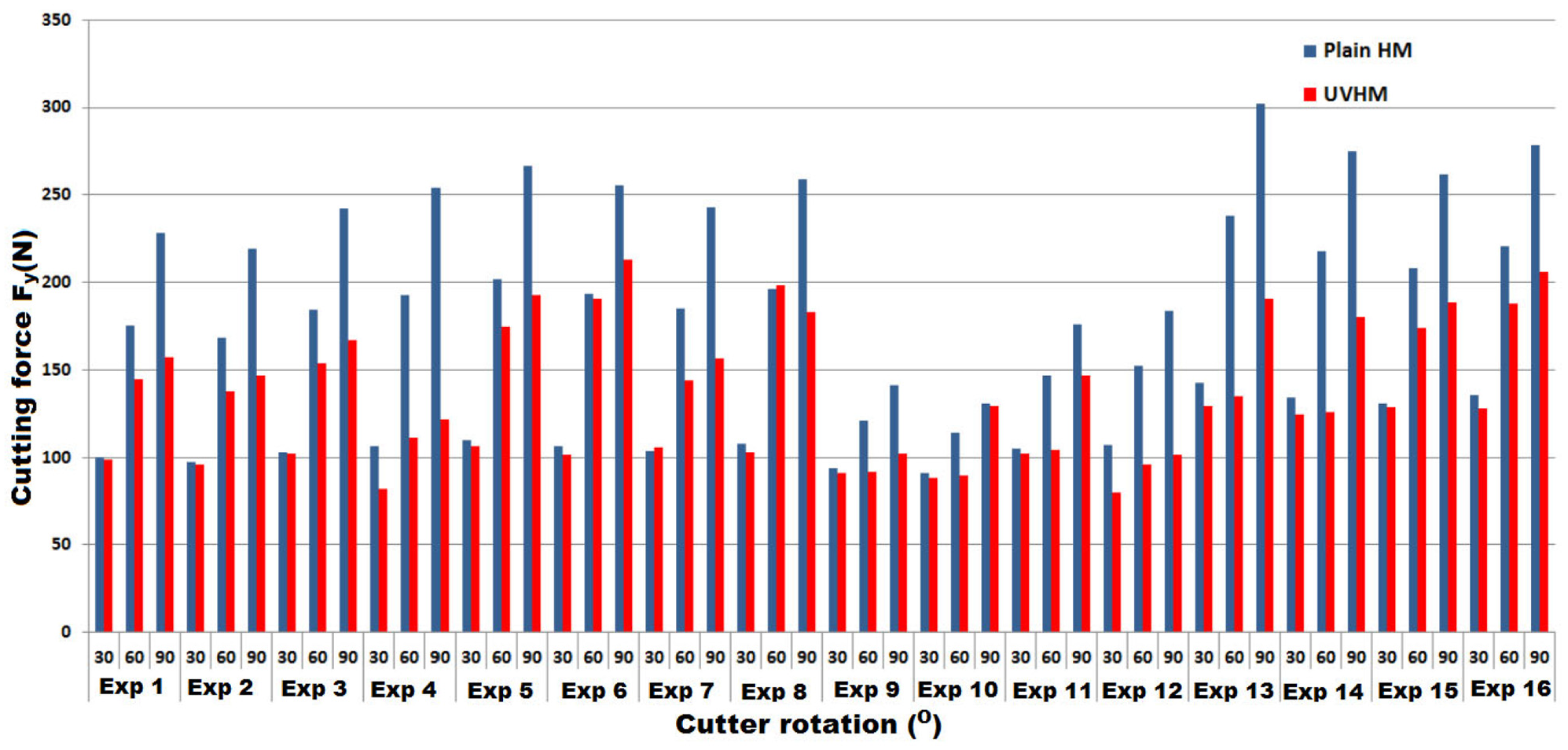
Cutting forces in y direction for plain and UVHM.
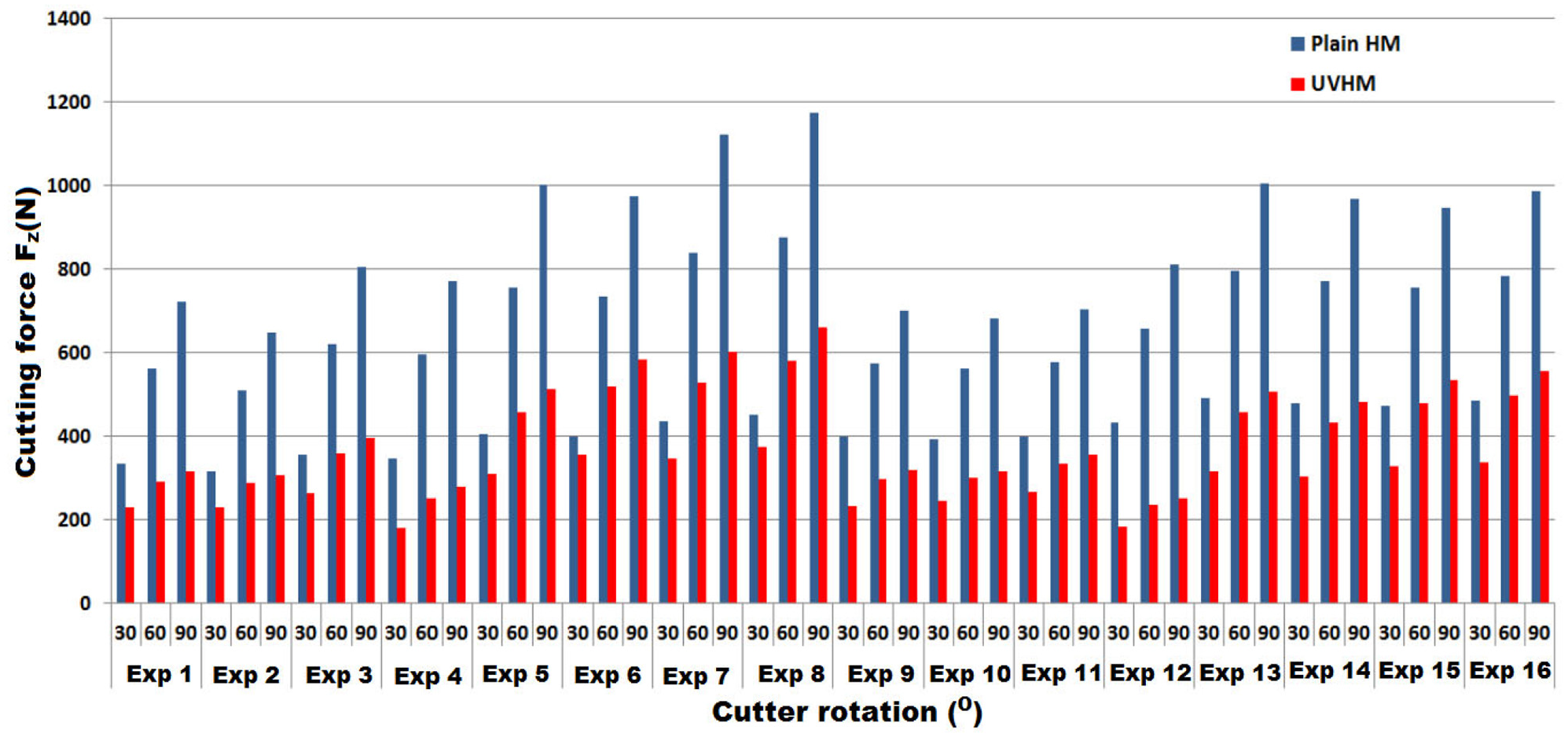
Cutting forces in z direction for plain and UVHM.
It is observed that the cutting forces in the UVHM are smaller than those of plain HM. It is also noticed that the difference between the forces in plain and UVHM for Fz is found larger than the forces in Xand Ydirections. As the UV is applied in z direction, the cutter spends more time separated from the workpiece in z direction. Hence, the axial force in UVHM is found less in percentage up to 47% when compared to plain HM, whereas the average difference between forces in plain and UVHM for Fx and Fy is found around 14%. There is a micro scale with no monotypic nature between the workpiece and tool which results in reduced cutting forces and improved surface quality. 14 The UV of tool provides more lubrication and cooling effect due to intermittent cutting which results in decreased forces in UVHM. 19 In another study, Xu et al. 46 also reported that the cutting forces are significantly reduced with the aid of UV. In both the milling processes, it is observed that the cutting forces in the three directions are found to be increased as the chip thickness and height increase. Based on the experimental results of chip geometry and cutting forces, it is summarised that smaller values of cutting forces are found for an 8 mm diameter mill cutter.
The power consumption is estimated using the equation (16) considering cutting forces in x, y and z directions at 30°, 60° and 90° of cutter rotation for the UVHM and plain HM. As the power consumption is directly affected by the cutting forces, the power consumption increased accordingly since the chip size increased. A comparison of power consumption for the both processes is presented in Figure 13. As the axial forces in UVHM are found smaller than those of plain HM, the power consumption is also found less in UVHM. The average reduction of power consumption in UVHM is found to be around 34%.
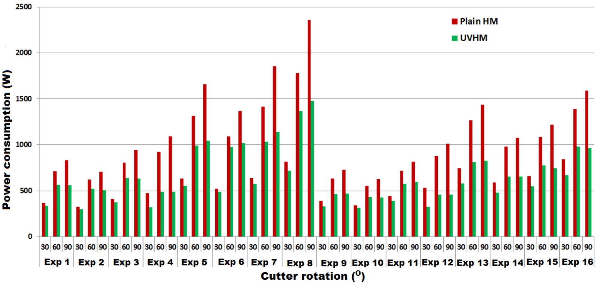
Power consumption in plain and UVHM.
Conclusions
In the present work, the ultrasonic vibration helical milling technique is used in making a hole on AISI 1020 steel. A power consumption model was developed in terms of cutting forces in x, y and z directions, tangential and axial feed speeds. Chip geometry is estimated at 30°, 60° and 90° of cutter rotation and forces in x, y and z directions and power consumption are estimated in plain and UVHM. The following conclusions are drawn from this study:
Chip geometry such as thickness and depth at 30°, 60° and 90° of cutter rotation are estimated. The thickness of the chip increased as the cutter bottom tooth rotates from 0° to 90° and then reduced, but the height of the chip increased as the cutter rotates till it leaves the workpiece. Taking into account the chip geometry in the estimation of the cutting force has helped in optimising the process parameter to increase the metal removal rate while reducing power consumption.
While estimating the power consumption, non-production activities are not taken into consideration. The power consumption in the present study is estimated by cutting forces and process parameters are optimised to reduce power consumption.
As the UV is applied in z direction, the cutter spends more time separated from the workpiece and the axial force in UVHM is found up to 47% less than that of HM. Similarly, resultant force of the forces in xand ydirections is found 14% less than the HM and the power consumption in UVHM is found 34% less than that of HM.
The process parameters are optimised and the 2000 rpm of cutter rotational speed, 156 rpm of cutter orbital speed and 0.3 mm of axial depth of cut using an 8 mm diameter cutter are found as optimum. A good agreement is found between the optimisation and experimental results with an average error of 4.36%, 2.51% and 3.92% for power consumption, chip thickness and depth respectively.
Footnotes
Appendix
Declaration of conflicting interests
The author(s) declared no potential conflicts of interest with respect to the research, authorship, and/or publication of this article.
Funding
The author(s) disclosed receipt of the following financial support for the research, authorship, and/or publication of this article: This work was supported by FIST-DST (Sanction No.: SR/FST/ETI-361/2014) and SERB-DST (Sanction No.: SERB/F/1761/2015-16).