
Abstract
Experimental study and theoretical calculation on the tool lives of free-cutting steels with different additions were carried out in terms of the friction characteristics, chip deformation, and normal stress distribution. The average friction coefficient, shear angle, and maximum normal stress were then calculated, and the influence of them on tool life was analyzed and discussed carefully. The free-cutting steel with Bi addition (MB) presented the best tool life of about 9200 and 5200 s at the speed of 150 and 200 m/min, respectively, which was mainly due to the combined effect of the lower average friction coefficient, maximum normal stress, and higher shear angle. When the cutting speed increased to 300 m/min, the tool life decreased rapidly, which was mainly caused by the serious tool wear behavior dominated by the high cutting temperature. Differing from the calculated results of shear angles based on Lee and Shaffer’s assumption, the measured shear angles decreased with the cutting speed ranging from 150 to 250 m/min, resulting from the thermal softening of workpiece material during machining. Moreover, the present findings indicated that the cutting process became unstable when the maximum normal stress on the tool nose was larger than 2 GPa, where catastrophic failures occurred, resulting in accelerated fracture of the tool. The research findings not only give more insight into the effect of friction characteristics, chip deformation, and normal stress distribution on the tool lives, but also have significance for the machining of free-cutting steels.
Introduction
As a derivative of traditional steel, free-cutting steel was firstly developed for its excellent machinability and acceptable mechanical properties. Additions of elements, such as sulfur, phosphorus, lead, selenium, bismuth, and calcium, are usually employed to improve its machinability. Those additions usually cause the formation of inclusions in steels, which can serve as stress-raisers in primary shear zones to enhance the chip breaking. They can also act as lubricant on the tool-chip interface, forming diffusion barriers to improve the tool wear behavior. The sulfurized free-cutting steel without lead has been widely used in industry due to its environmentally friendly characteristic, which has drawn a great deal of research attention during past decade.
The machinability of free-cutting steel was widely investigated in terms of additions. Tanaka et al. 1 researched the machinability of free-cutting steel with hexagonal boron nitride addition, and found that the tool wear can be significantly improved due to the diffusion barrier layer on the tool-chip interface formed during machining. Akasawa et al. 2 added free-cutting additions to austenitic stainless steel, and experimental study was conducted to reveal the effect of additions on machined surface quality. Thereafter, Liu and Chen 3 studied the effect of oxygen content on the machinability of sulfurized free-cutting steel. The best tool life and surface quality were obtained when the total oxygen contents were 0.0105 and 0.0125 wt.%, respectively. Zhang et al. 4 investigated the influence of tellurium addition on the morphology of inclusions in Y15 free-cutting steel. Tanaka et al. 5 found that, during the machining of BN free-cutting steel, the use of TiC based ceramic insert can improve the tool wear behavior by forming a protective nitride layer on the tool-chip interface. Furthermore, the effects of MnS and BN inclusions on the machinability of free-cutting steel were also studied by Chen et al. 6 Desaigues et al. 7 found that the MnS inclusions would accumulate on the sliding and shearing zone of the tool rake face during machining and eventually evolve into a built-up layer (BUL). Zhang et al. 8 concluded that the MnS inclusions, steel matrix properties, and lubricant layer were the main reasons for the improvement of the machinability of free-cutting steel. Besides, Ray et al. 9 enhanced inclusion spacing as well as aspect ratio by cold deformation, and the machinability of free cutting steel was investigated in terms of cutting force, surface quality, and chip formation.
In addition to the influence of additions on machinability, many researches were further conducted to study the effect of cutting parameters on cutting performance, including surface quality and tool life. Krahmer et al. 10 found that the free-cutting steels had big advantages in tool life at low (150 m/min) and medium (180 m/min) cutting speeds. However, the advantages were progressively reduced when the cutting speed increased to 240 m/min. Varghese et al. 11 optimized the cutting parameters based on the surface roughness. Besides, Almeida et al. 12 presented a robust optimization approach using mean square error for the AISI 12L14 free-cutting steel machining. Krahmer et al. 13 evaluated the machinability during the turning of three kinds of free-cutting steels (SAE 1212, SAE 12L14, SAE 1215) under dry and wet conditions, respectively. The wear behavior of cutting tools at different cutting speeds (150, 180, and 240 m/min) was also reported. Thereafter, Qin et al. 14 studied the effect of microstructure characteristics on machinability, and concluded that the structure defects, such as grain boundaries and inclusions, were the main reasons for the enhancement of machinability. The machining of AISI 1215 steel with multi-layer (Al2O3/TiCN) coated carbide insert was conducted by Xu et al. 15 A MnS lubricant layer was observed on the tool-chip interface during machining, and acted as lubrication and diffusion barriers. Wear behavior of cutting tool is an important indicator for evaluating the machinability of workpiece material, which is also the focus of researches in the field of processing.16–19 Then wear behaviors, such as the abrasive wear, adhesive wear, diffusion wear, and oxidation wear on the rake face and flank face of cutting tools, are usually experimentally studied.20–22 Scanning electron microscope (SEM) and energy dispersion spectrum (EDS) are usually conducted to analyze the micrograph of worn area.23–25 For free-cutting steels, wear behavior and tool life can also be investigated using SEM and EDS analysis of worn out inserts. 26
However, these studies on the tool wear of machining free-cutting steels mainly focused on the lubricant layer on the rake face and inclusion forms in steel. It is still necessary to uncover the characteristics of cutting tools during machining. The temperature and stress during machining are significantly dependent on the normal stress, friction stress on the tool rake face, and chip deformation in the shear deformation zone, which are also the internal reasons for tool wear. Thus, the cutting characteristics, such as friction characteristics, chip deformation, and normal stress distribution, should also be considered during the analysis of tool wear,27,28 which can reveal the variation law of tool life more comprehensively. Therefore, in this research, in order to further study the influence of friction characteristics, chip deformation, and normal stress distribution on tool wear, experimental study, and theoretical analysis of turning free-cutting steel were conducted. The present findings are important for revealing the wear behavior of machining free-cutting steel and promoting its application in industrial production.
Experiments
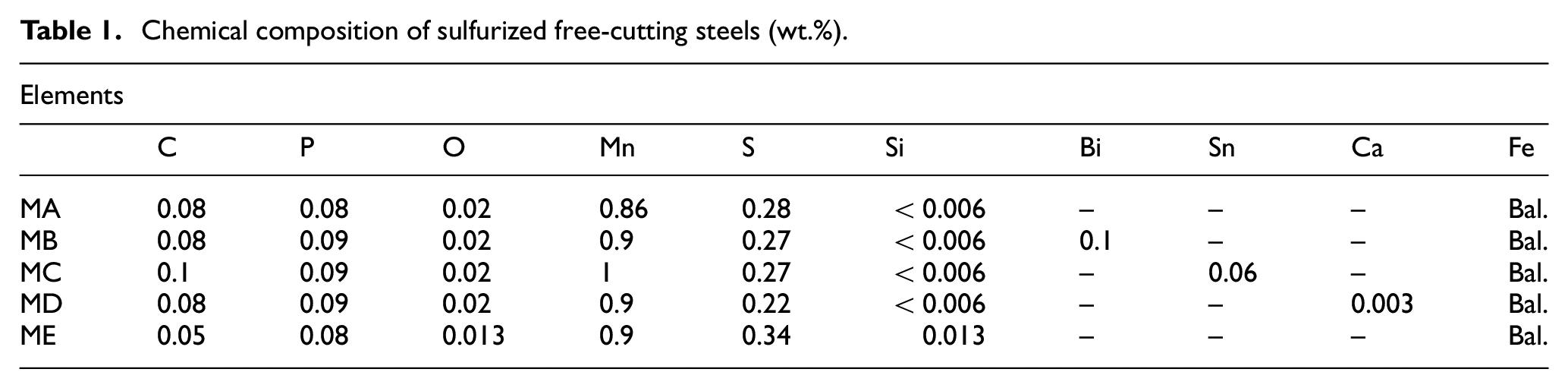
In order to investigate the effect of additions on the machinability of free-cutting steels, five different kinds of sulfurized free-cutting steels were prepared. 26 Among them, Material A (MA) was the traditional sulfurized free-cutting steel. Based on MA, Material B, C, D, and E were sulfurized free-cutting steels with additions of Bi, Sn, Ca, and Si respectively. The detailed chemical compositions of the workpiece materials were shown in Table 1. The sulfurized free-cutting steel bars used in this research were in the size of Φ100 × 260 mm.
Chemical composition of sulfurized free-cutting steels (wt.%).
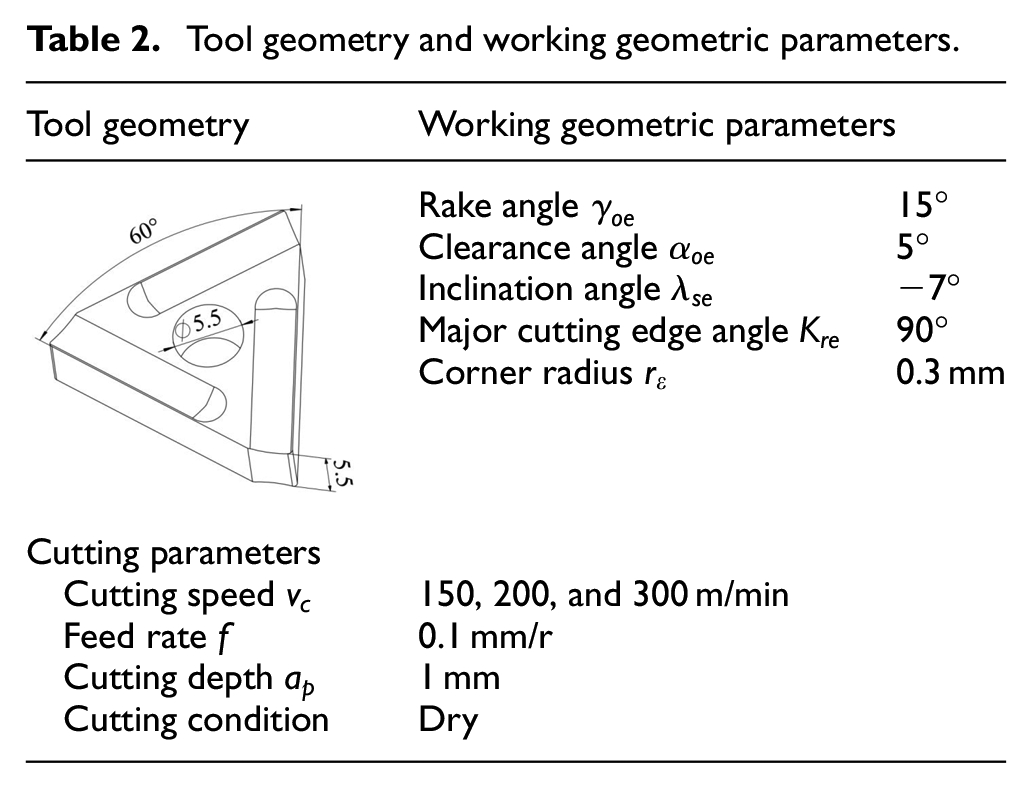
Commercial cemented carbide inserts (YT15 31303C uncoated) were used to machine the free-cutting steels at three kinds of cutting speeds (150, 200, and 300 m/min). The tool geometry, working geometric parameters and cutting parameters were presented in Table 2. The turning experiments were carried out on a CA6140 lathe, which was equipped with a frequency converter (3G3RV-A4075-ZV) to keep the cutting speed constant when the diameter of the workpiece decreased.
Tool geometry and working geometric parameters.
The average flank wear width (VB) was measured with a tool maker’s microscope (XTL-340E). The wear criterion was chosen as average flank wear VB = 0.3 mm, at which the cemented carbide inserts can be fully used and the damage due to excessive wear can also be prevented. The machining was terminated when the average flank wear width reached the wear criterion. The tool wear curve was obtained by measuring and recording the average flank wear width at particular times. The cutting forces of axial force Fx, radial force Fy, and main cutting force Fz were measured using a three-dimensional dynamometer Kistler 9257B with high resolution and reliability. The measuring ranges of the dynamometer were 5, 5, and 10 kN for Fx, Fy, and Fz, respectively, and the threshold was less than 0.01 N. A fast tool lowering device was used to measure the shear angle of the chip shear deformation zone. The experimental setup is given in Figure 1.
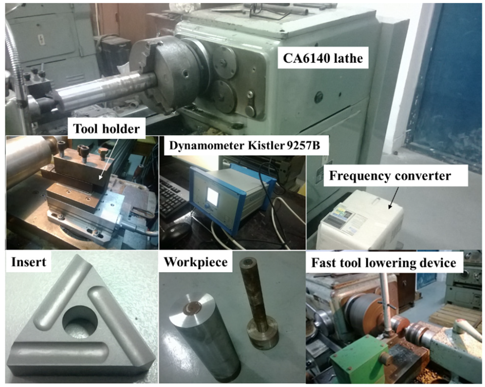
Experimental setup used in this research.
Results and discussion
Tool life and cutting force
During machining, the average flank wear width was measured with the microscope at particular times, as shown in Figure 2. The average flank wear curves of turning free-cutting steels (MA, MB, MC, MD, and ME) at different speeds were presented in Figure 3. In order to study the variation trend of tool life from low-speed to high-speeding machining, three kinds of speeds (150, 200, and 300 m/min) were selected in this research. The results indicated that the free-cutting steels showed excellent machinability at the speed of 150 m/min, and the tool lives of MA, MB, MC, MD, and ME can reach 6420, 9200, 5410, 4130, and 3040 s, respectively. However, it would decrease rapidly with the cutting speed increasing from 150 to 300 m/min. When the cutting speed increased to 200 m/min, the tool lives decreased to 880–5200 s. And it was less than 600 s when the cutting speed increased to 300 m/min, showing poor machinability. Generally, tool wear went through three stages named initial stage, stable stage, and rapid stage. At the speed of 150 m/min, the distinction of the three wear stages was obvious as presented in Figure 3(a). When the speed increased to 200 and 300 m/min, the difference became small and even disappeared, as shown in Figure 3(b) and (c). Although a higher cutting speed can improve the machining efficiency, it can also enhance the cutting temperature and cause a degradation in tool life. The results indicated that the free-cutting steels used in this research were not suitable for high-speed machining with YT15 inserts. At the speed of 150 and 200 m/min, the tool lives of MA, MB, MC, MD, and ME showed a certain consistency. MB has the best tool life and ME has the poorest tool life, as presented in Figure 3(a) and (b) respectively. It can reach 9200 s during the machining of MB with YT15 inserts at the speed of 150 m/min, at which the tool life of ME was only 3040 s and that of MA, MC, and MD were between them. Thus, MB showed a better machinability than other materials during medium (200 m/min) and low-speed (150 m/min) machining. It also indicated that the tool life of free-cutting steel can be improved with moderate Bi addition and suppressed with excessive Si addition. It almost remained unchanged with Sn or Ca addition at the medium and low-speed machining.
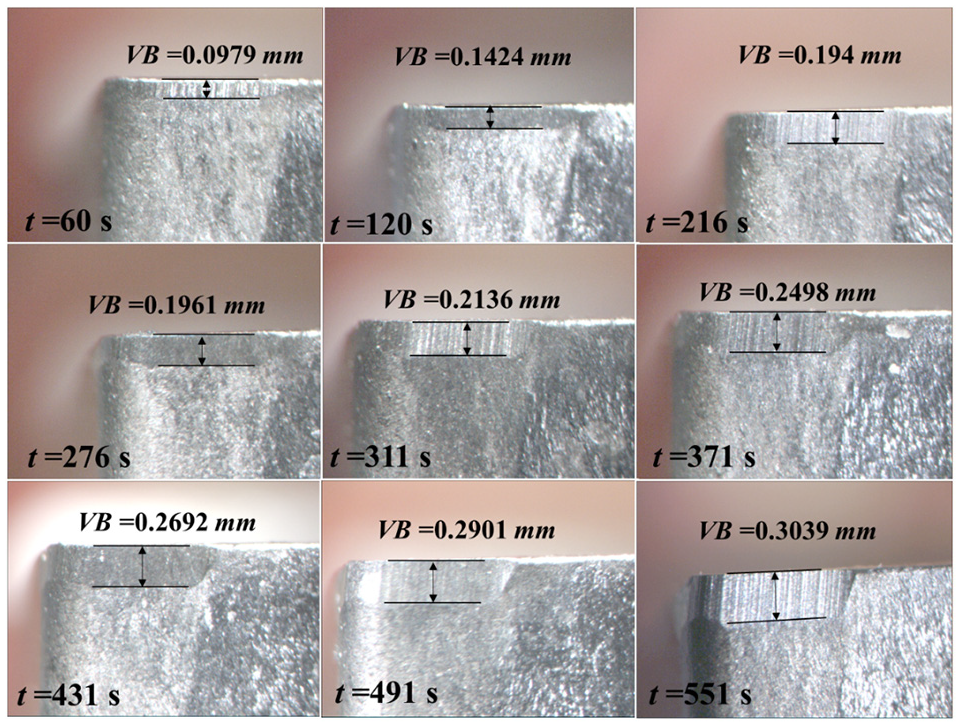
Average flank wear width of MC (300 m/min) measured at particular times.
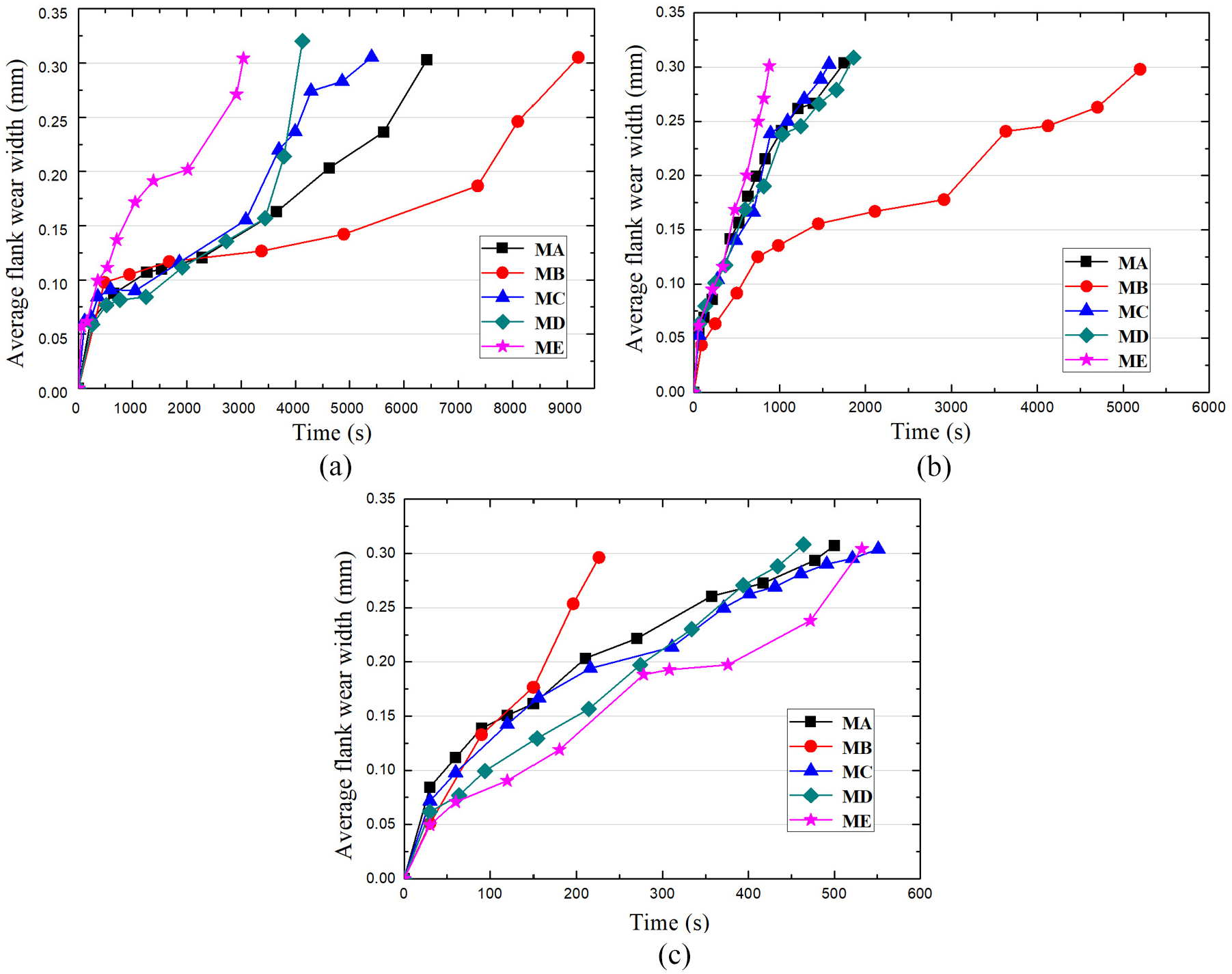
Average flank wear curves at the speed of: (a) 150 m/min, (b) 200 m/min, and (c) 300 m/min, respectively.
In order to study the cutting force during machining, new inserts were prepared to machine MA, MB, MC, MD, and ME at different speeds (150, 200, and 300 m/min). The cutting forces of Fx, Fy, and Fz were measured with the dynamometer Kistler 9257B during machining. For each condition, the turning process was repeated for three times and the average value was calculated and recorded after removing the zero-drift error of the dynamometer. The results of cutting forces at different speeds were presented in Figure 4. It can be seen that for different speeds, the main cutting force Fz was always the largest one and followed by the axial force Fx. Here, the relatively large cutting depth (1 mm) and major cutting edge angle (90°) were the main reasons for the high axial force Fx and low radial force Fy. Overall, the axial force Fx, radial force Fy, and main cutting force Fz decreased slightly when the cutting speed increased to 300 m/min. The increase of cutting speed would also enhance the cutting temperature.10,29 The slight reduction of cutting force can be attributed to the thermal softening effect of free-cutting steel materials during machining.30–32 Combined with the results of tool lives (Figure 3), it seems that the rapid decrease of tool lives at the speed of 300 m/min can also be attributed to the high temperature, which can intensify the main wear behaviors, such as adhesive wear and diffusion wear.
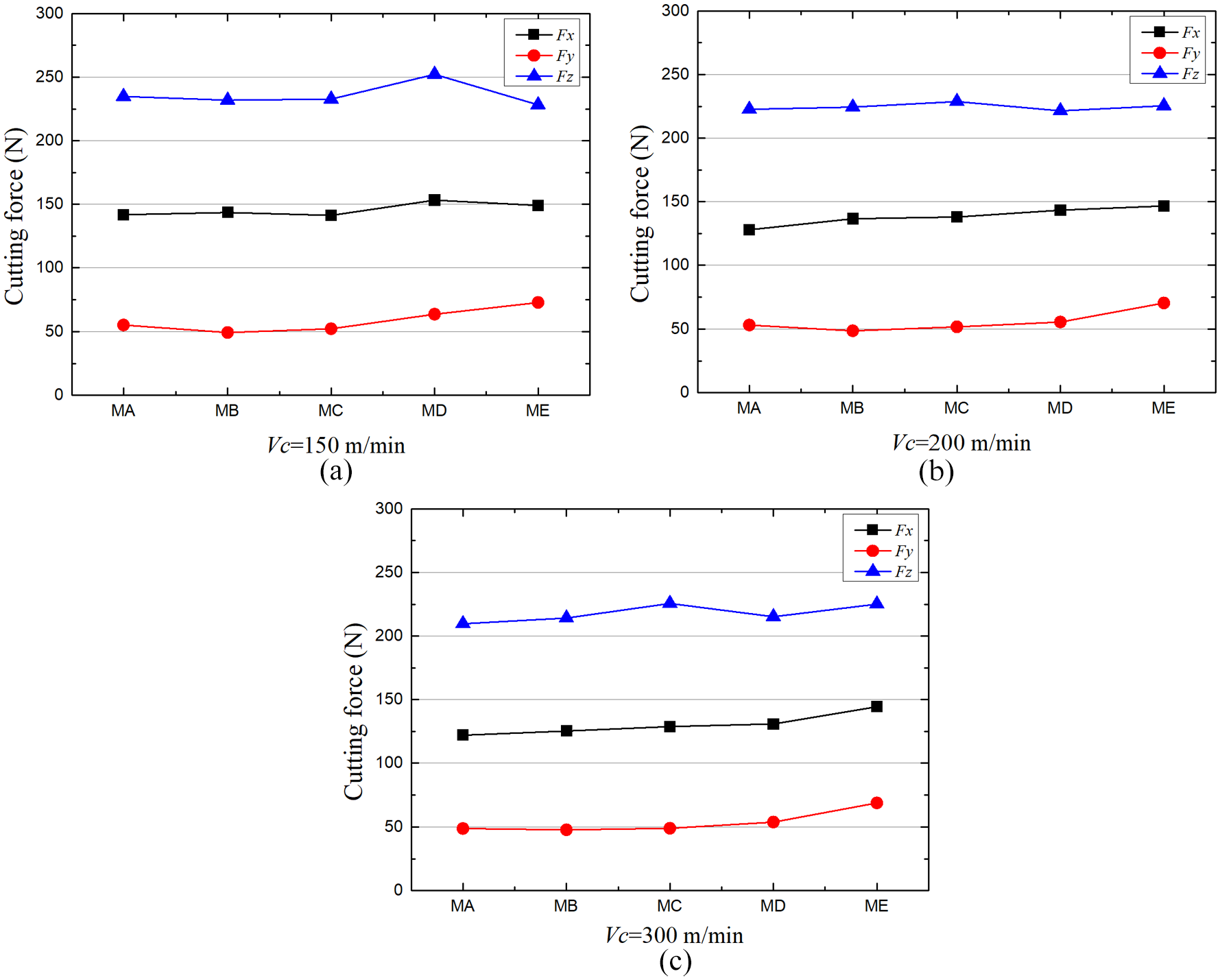
The cutting forces of machining different materials with YT15 inserts at the speed of: (a) 150 m/min, (b) 200 m/min, and (c) 300 m/min, respectively.
Friction characteristics and shear angle
During the machining of free-cutting steels, the flank wear was closely related to the wear behavior on tool nose and rake face. Generally, tool wear first occurred on the tool nose, and then it would aggravate the wear behaviors on the flank face and rake face at the same time. Although the friction force of tool-workpiece interface cannot be obtained directly, the flank wear can be analyzed with tool-chip interface friction characteristics and normal stress distribution, which were closely related to the wear behaviors on the tool nose and rake face. Then the tool-chip interface friction characteristics can be characterized by the average friction coefficient

Here,
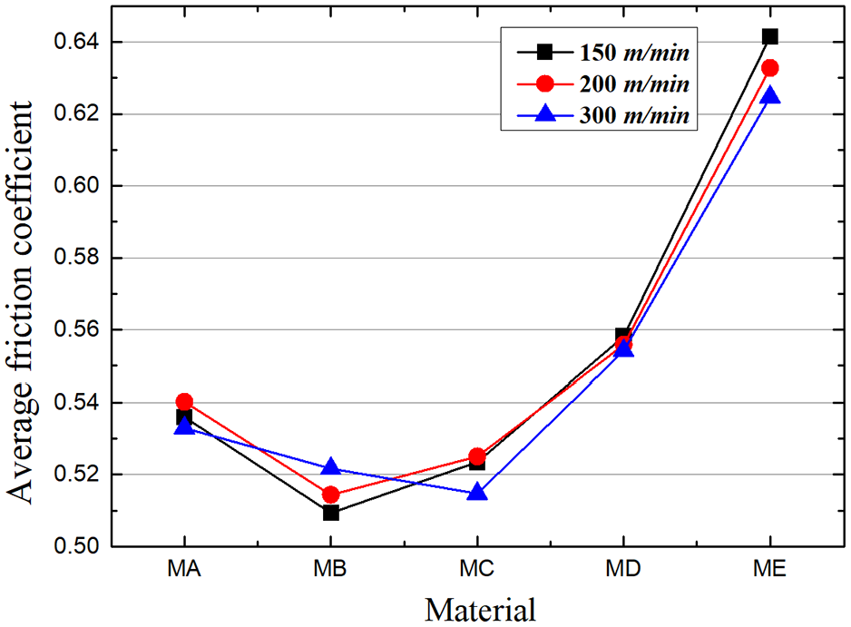
The average friction coefficient on tool-chip interface for five materials.
The cutting heat generated on the chip shear deformation zone was one of the prime reasons, which lead to the increase of cutting temperature. In addition to the friction characteristics, the shear angle was also closely related to the cutting temperature and chip deformation. Based on the friction angle

The shear angles of five materials at different speeds were presented in Figure 6. For each material, the variation of shear angles was small even with the increase of cutting speed from 150 to 300 m/min. However, the difference in shear angles was obvious for different materials. It indicated that the shear angle was mainly influenced by material properties rather than cutting speed. At the speed of 150 and 200 m/min, ME had the lowest value of shear angle, while MB had the highest value. Combined with the results of Figure 3, the tool life can also be influenced by shear angle, just same as the friction characteristics. Here, shear angle usually reflects the degree of chip deformation, and a relatively low shear angle means a higher chip deformation ratio. Then more cutting heat will generate on the chip shear deformation zone during machining, which can also lead to the increase of cutting temperature and intensify the tool wear.
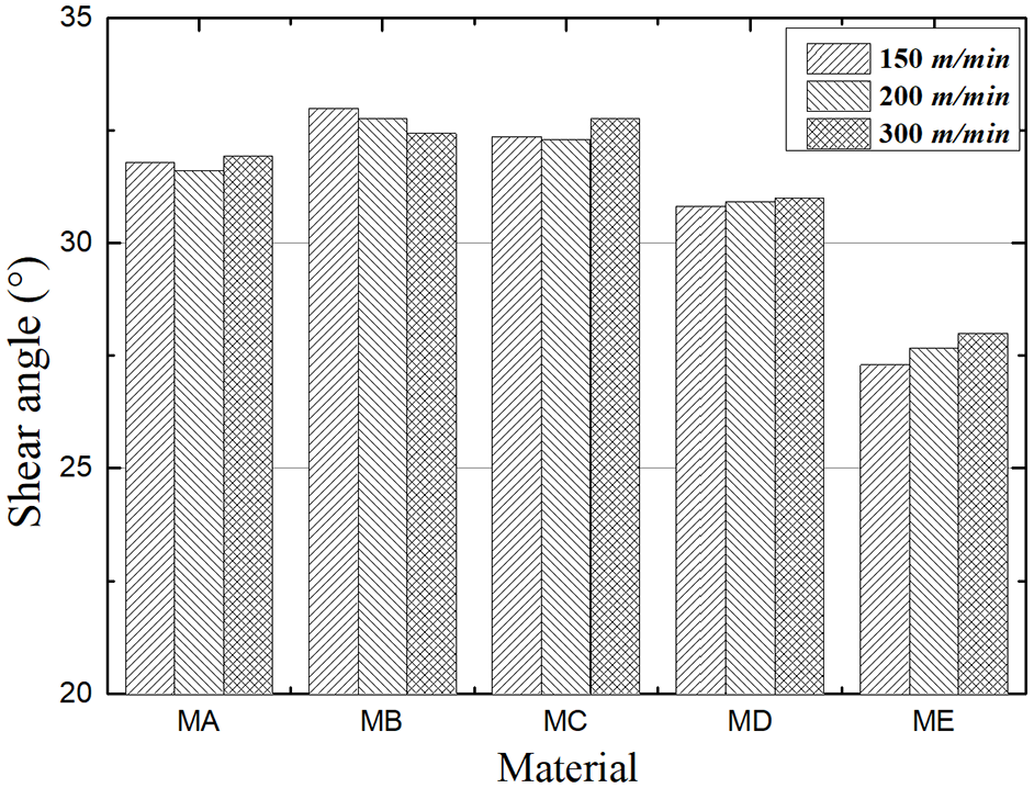
The shear angles of five materials at different speeds.
In order to confirm the calculated shear angles, a fast tool lowering device was used, which can effectively obtain the chip root sample with the cutting speed less than 250 m/min. The chip root samples of MA and MD at different speeds (150, 200, and 250 m/min) were measured. After the process of inlaying, rough grinding, fine grinding, and etching, the metallographic structure of chip shear deformation zone was finally obtained, as presented in Figure 7. The cutting layer thickness a and the chip thickness ac were measured. The chip deformation coefficient can be calculated with

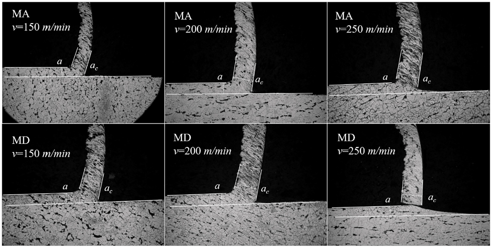
Metallographic structure of chip shear deformation zone for MA and MD.
The shear angle

The shear angle results, measured with chip deformation coefficient, were given in Figure 8, as compared with the calculated results based on Lee and Shaffer’s assumption. For the measured results, shear angle decreased with the increase of cutting speed. However, it almost kept constant for calculated results. The distinction was mainly due to the effect of cutting temperature on material properties. With the increase of cutting speed and temperature, the workpiece materials would be softened by the cutting heat generated from the chip shear deformation zone. The degree of chip deformation would also be intensified. Then the measured result of shear angle decreased obviously with the increase of cutting speed. For the calculated result of shear angle, the friction angle was determined by the ratio of Fy to Fz. Here, both the radial force Fy and main cutting force Fz decreased with the increase of cutting speed and temperature. The influence of cutting speed was weakened during the calculation of friction angle and shear angle. Finally, the calculated result of shear angle almost kept constant even with the change of cutting speed. Besides, the shear angle of MA was larger than that of MD at different speeds, which was the same in the calculated and measured results. A larger shear angle indicated a lower chip deformation ratio and less chip shear deformation heat, which was beneficial to the tool life. This explains why the tool life of MA was better than that of MD at the speed of 150 m/min. With the increasing of cutting speed to 250 m/min, the difference in shear angle of MA and MD was also smaller. The shear angles of five materials would be almost the same at the speed of 300 m/min, corresponding to the similar results of tool lives as shown in Figure 3(c). Thus, the variation of shear angle was also related to the tool wear behavior in terms of temperature. In addition to the difference in variation trend, for each material the difference between calculated and measured shear angle values was small especially for low and medium-speed machining. It can also verify the validity of the calculated results of shear angle to some extent.
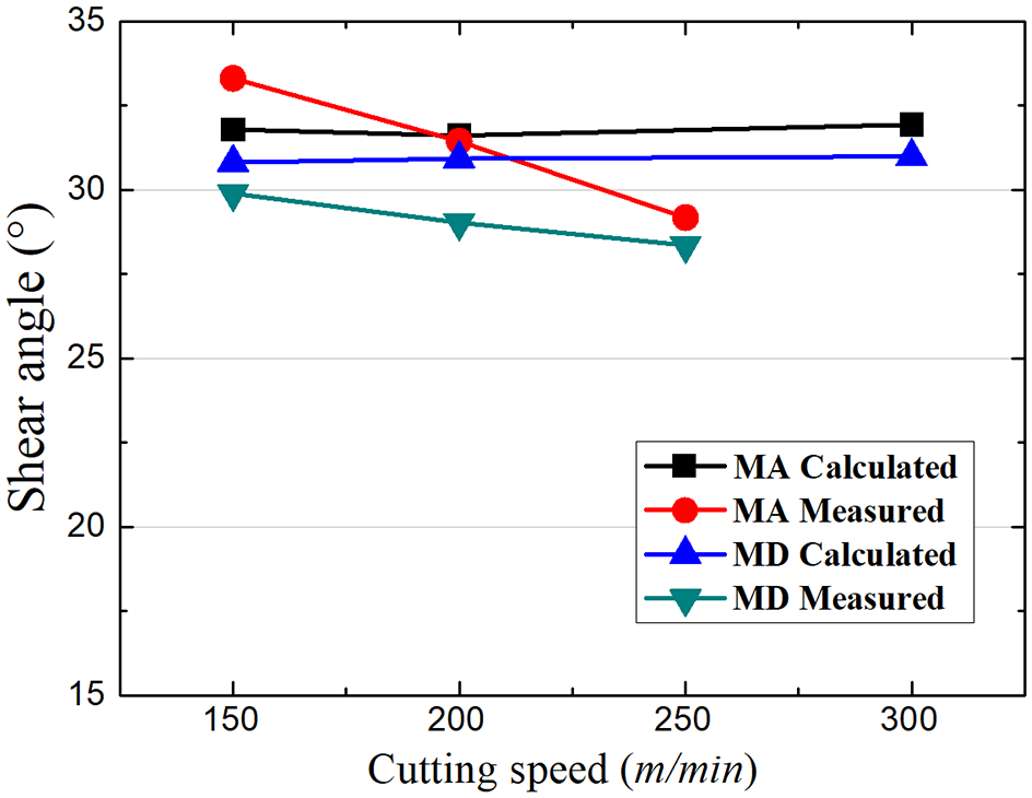
Measured and calculated results of shear angle.
Maximum normal stress
In addition to the friction characteristics and shear angle, the normal stress distribution on the tool rake face can also influence the tool life. According to Zorev’s assumption,35,36 normal stress has the maximum value at the tool nose and then decreases gradually to zero at the tool-chip separation boundary. The flank wear is always accompanied with the wear behavior on the tool nose and rake face, which is closely related to the maximum normal stress. Figure 9 presented the forces acting on the shear plane, chip, and tool rake face.
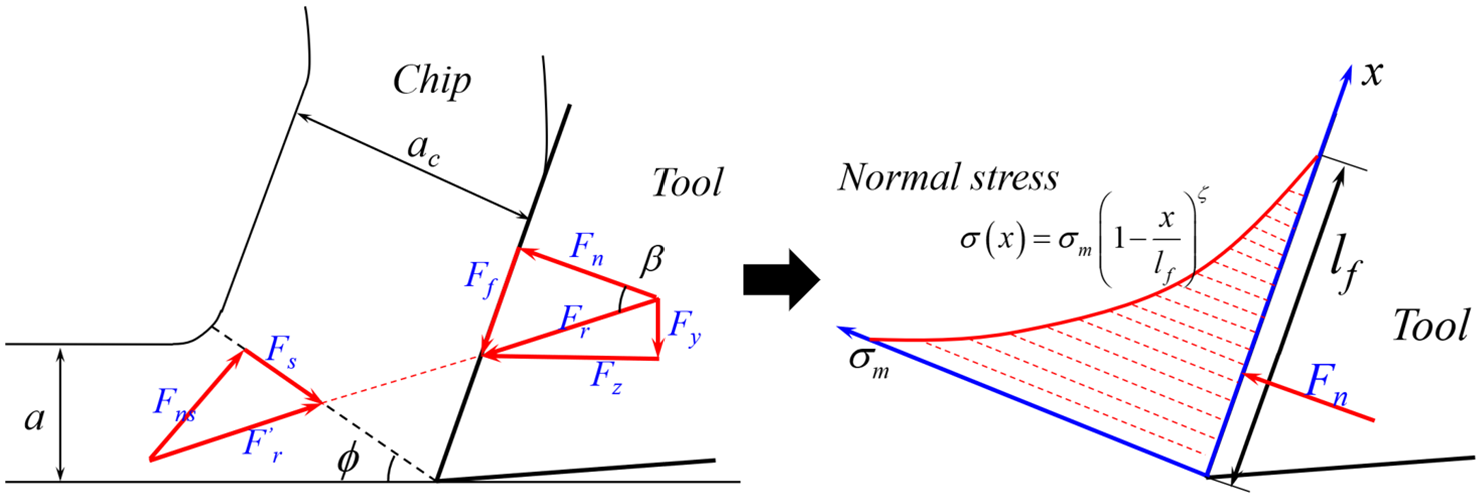
Forces acting on the shear plane, chip, and tool rake face.
The normal stress distribution function

Here,
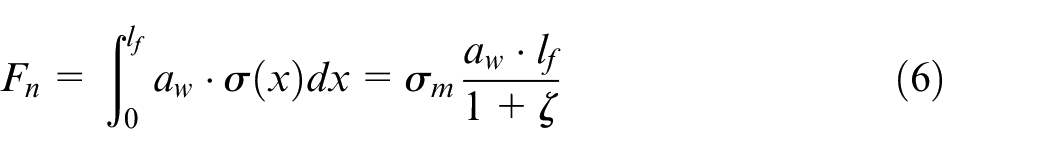
where
The resultant normal stress

Combining equations (6)–(8), the maximum normal stress can be calculated as:

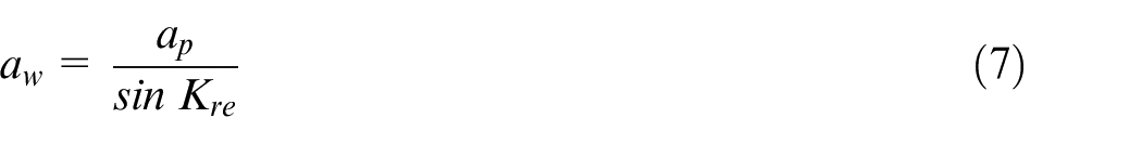
In order to examine the maximum normal stress on the tool nose, the tool-chip contact length
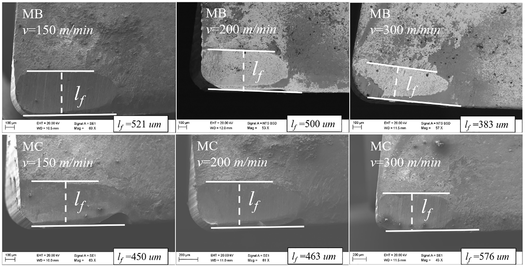
SEM micrographs of worn-out inserts at different speeds.
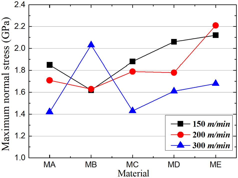
Maximum normal stress on the tool nose at different speeds.
The maximum normal stress decreased obviously with the increase of cutting speed, except for MB because of the appearance of fracture. Based on the research findings as mentioned in Figure 3, the tool life decreased obviously with the increase of cutting speed. In addition to the influence of cutting temperature, the tool life was also influenced by the wear behavior on the tool nose characterized with maximum normal stress at the speed of 150 and 200 m/min. When the speed increased to 300 m/min, the cutting temperature became the dominate factor affecting the tool life. The tool life decreased obviously even with relatively small maximum normal stress at this situation. Besides, when the maximum normal stress on the tool nose was too high, for example more than 2 GPa for MB at the speed of 300 m/min, catastrophic failure was more likely to happen, which would also reduce the tool life significantly. In conclusion, the maximum normal stress at the tool nose can effectively reflect the tool life during medium and low-speed machining. A lower maximum normal stress means a better wear behavior on the tool nose, which is beneficial for improving the tool life. Besides, an extremely high maximum normal stress will also make catastrophic failure on the tool nose more likely to happen, leading to the reduction of tool life.
Free-cutting steels have widespread industrial applications for its excellent machinability and acceptable mechanical properties. The present findings can provide a good guidance on the machining of free-cutting steels in industrial applications. For medium and low-speed machining of free-cutting steel, a better tool life can be obtained with moderate Bi addition, which was characterized with a lower average friction coefficient, maximum normal stress, and higher shear angle. Moreover, catastrophic failure of the tool, dominated by the extremely high maximum normal stress on the tool nose, can reduce the tool life. The present findings also provide a new approach to the analysis of tool life.
Conclusions
The tool lives of free-cutting steels with different additions were analyzed in terms of the friction characteristics, chip deformation, and normal stress distribution, in order to reveal the variation rules of tool life. The main findings are concluded as follows:
For medium and low-speed machining, the tool life of free-cutting steel can be improved by the addition of moderate Bi (MB), and suppressed by addition of excessive Si. The tool lives of all materials will decrease rapidly with the increasing of cutting speed to 300 m/min, which is mainly due to the high temperature and serious tool wear.
The friction characteristics, chip deformation, and normal stress distribution can effectively reflect the tool life during medium and low-speed machining. A better tool life can be characterized with a lower average friction coefficient, maximum normal stress, and higher shear angle.
The shear angle decreases with the increasing of cutting speed from 150 to 250 m/min, which can be attributed to the thermal softening of workpiece material during machining. A lower maximum normal stress means a better wear behavior on the tool nose, improving the tool life. The tool life will be significantly reduced with the extremely high maximum normal stress on the tool nose.
Footnotes
Declaration of conflicting interests
The author(s) declared no potential conflicts of interest with respect to the research, authorship, and/or publication of this article.
Funding
The author(s) disclosed receipt of the following financial support for the research, authorship, and/or publication of this article: This work was mainly supported by the Natural Science Foundation of Anhui Province [grant number 2108085ME171], Fundamental Research Funds for the Central Universities [grant number JZ2020HGTA0084], and Key Laboratory of Electric Drive and Control of Anhui Higher Education Institutes, Anhui Polytechnic University [grant number DQKJ202101].