
Abstract
An experimental investigation was conducted to determine the form and characteristics of damage that temporary fasteners may cause to the composite hole in the aviation temporary fastening process. According to the shapes of the temporary fastener clamping feet, copying indenters were designed. The similarity between the quasi-static indentation (QSI) experiment and the installation of temporary fasteners was discussed. The QSI experiment was used to investigate the influence of shapes of clamping feet, prepreg category, installation direction, and other factors on the failure of the composite hole, and the displacement-load curves were obtained. The damage morphology was observed with the optical microscope and ultrasonic microscope. The results show that the QSI experiment can simulate the temporary fastening damage well. Due to the expansion of delamination, and the final occurrence of fiber breakage in the composite hole, the bearing capacity is reduced. The temporary fastening damage process can be divided into three stages: in the elastic stage, the laminate does not suffer damage, and the surface resin appears slight dents; in the delamination stage, the layers delaminate at the edge of the contact surface, and expand in the direction of fiber; in the failure stage, sudden damage occurs suddenly under the indenter, and the fiber matrix is crushed into powder. The propagation range of the damage depends on the material properties and installation direction. Compared with T700/3234, T800/X850 has greater energy absorption before the damage. Laminates have the worst anti-intrusion ability out-of-plane in the surface fiber direction. These results increase the understanding of the out-of-plane compression damage of the composite material and provide a theoretical basis and method guidance for the control of the temporary fastening damage of the composite structures. The copying indenter designed in this paper can be used for further research on temporary fastening damage.
Introduction
In the aviation assembly, due to the far distance between the positioning and clamping devices of the frame, the thin-walled components need to be pre-connected in advance to eliminate the initial gap, suppress the hole gap, and improve the positioning accuracy. 1 Since this connection undergoes multiple disassembly and assembly during the entire assembly process, it is called temporary fastening. Related manufacturers have also introduced special fasteners for this process, which are called temporary fasteners (Figure 1). At present, the temporary fasteners commonly used by aviation manufacturers can be roughly divided into bean-shaped, cone-shaped, and cylinder-shaped according to the geometry of clamping feet.
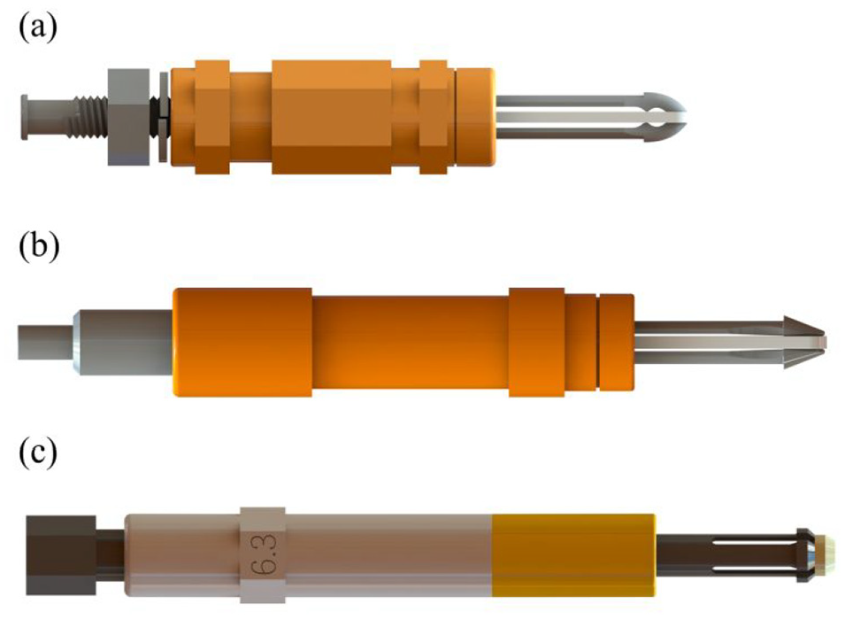
Three types of temporary fasteners: (a) bean-shape: Monogram HNXL, (b) cone-shape: Monogram CBXL, and (c) cylinder-shape: Lisi CLY 41CC.
With the development of aviation materials, the temporary fastening process is facing challenges. The application objects of the traditional temporary fastening technology are mostly aluminum alloy components. Due to the weak rigidity of the metal structures, the temporary fastening force that needs to be applied is often small. So there is no temporary fastening damage problem at the installation site. However, with the gradual increase in the proportion of carbon fiber reinforced plastics (CFRP) material with the advantages of low specific gravity, high strength, and good fatigue resistance in aviation, 2 the traditional temporary fastening technology is no longer applicable. In the actual assembly site, temporary fasteners are likely to cause damage to the composite hole because of the small clamping surface, resulting in undesired repair and scrapping. As stated in Mo and Suparayan, 3 the application of CFRP is not easy because of its high brittle and toughness. Therefore, the ultimate care needs to be taken with this material to avoid damage in the manufacturing process. The development of temporary fastening technology suitable for composite components requires investigating the damage modes and failure mechanism of composite holes. 4 Therefore, this paper uses experiments to explore the temporary fastening installation process.
The composite pore structure is often designed to withstand in-plane loads, and its damage forms are also well summarized as Net-tension failure, Shear-out failure, Bearing failure, and Cleavage failure. 5 When temporary fasteners are installed, the composite hole is subjected to a compressive load in the thickness direction. At present, there are few studies on this load method. Poe. 6 performed quasi-static compression on the supported laminate through a spherical indenter, and pyrolysis is used to remove the matrix to observe the fiber damage. Broken fibers were found in the outermost layer directly below the contact point. Jorgensen et al. 7 conducted a thickness compression test on the supported cross-ply lay-up, and found that the first sign of failure was the lamination near the contact edge. He pointed out that laminates with different stacking directions perform better in resisting compressive loads in the thickness direction. O’Masta et al. 8 conducted a supported quasi-static indentation test on cross-ply polymer laminates reinforced by ultra-high molecular weight polyethylene fibers and tapes with a flat-bottomed cylindrical punch, and found that the thickness direction compressive strength of the laminate is enhanced due to the indirect fiber stretching mechanism. Attwood et al. 9 used a high-speed camera to study the impact damage mechanism of laminates with back support, and found that fiber indirect tensile fracture is the main damage mode. Yu et al.10,11 studied the sensitivity of strain rate and curing state to the out-of-plane compression response of laminates. With the increase in the shear strength of the matrix, the through-the-thickness compressive performance of the laminated plate increases, and the sensitivity to strain rate decreases. However, there is no report about the damage of temporary fastener installation.
Since the installation of temporary fasteners is a low-speed process, the contact process between the clamping feet and the composite hole is relatively slow, so this article considers using a special indenter on a universal testing machine to simulate temporary fastening damage. The advantage of this is that on the universal testing machine, the pressure and rate of loading can be precisely controlled, and it can be easily interrupted at different stages to observe the damage evolution in the board because it is a quasi-static experiment. This part of the research idea is developed from the literature.12–14 Whether the temporary fastener installation experiments can be replaced by quasi-static indentation experiments still needs to be discussed in this article.
Therefore, this paper conducted temporary fastener installation experiments and quasi-static indentation experiments on T800/X850 laminates. Ultrasonic microscope and optical microscope were used to observe the form of damage to compare the similarity of the two experiments. The damage form and failure mechanism around the composite hole during the temporary fastening process were investigated, and the influence of clamping feet, composite material type, stacking sequence, installation direction, and other factors on the damage of the composite hole was analyzed. The experimental method proposed in this paper can also be used to determine the maximum pre-tightening force of bolts, 15 rivets, 16 and self-tapping screws 17 used in composite structures.
Experimental method
Materials and stacking sequences
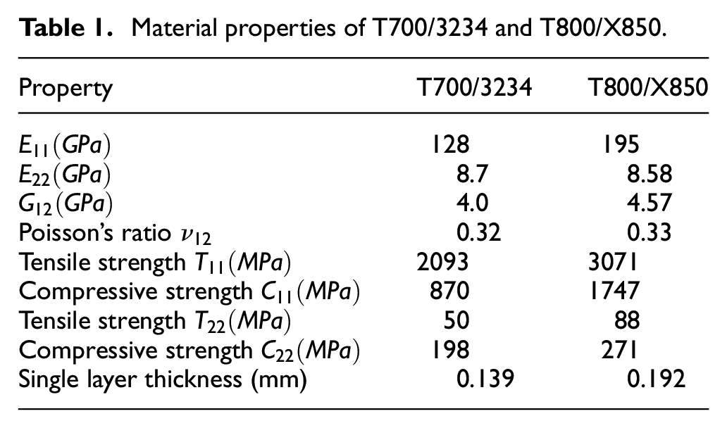
The laminates are made of T800/X850 prepreg and compared with T700/3234. The curing temperature of T800/X850 is 456 K, the curing time is 4 h, and the curing pressure is 0.6 MPa. The curing temperature of T700/3234 is 433 K, the curing time is 3 h, and the curing pressure is 0.68 MPa. The material performance of CFRP is included in Table 1. 18 It can be seen that the transverse compressive strength of T800/X850 is 36.9% higher than that of T700/3234. The stacking sequence of the laminates is [+45/−45/0/+45/90/−45/+45/90/−45]s. Ultrasonic microscopy is used to inspect the composite laminate to ensure that there are no void-like defects inside, which can avoid affecting the experimental results. 19
Material properties of T700/3234 and T800/X850.
CFRP specimens
Designing composite specimens according to ASTM D5961. 20 It satisfies the margin/aperture ≥ 6, 1 ≤ aperture/plate thickness ≤ 3, which can avoid the influence of the edge on the hole, and is close to the actual engineering application scenario. In order to avoid the interference of initial damage to the installation experiment of temporary fasteners, the test pieces are all cut by water jet. 21 The CVD diamond-coated brad spur drill22,23 is used to drill from the rough side to the other side, and the exit side is padded with wood. The side length of composite specimens is 60 mm × 40 mm, and the hole diameter is 6.38 mm. The smooth side is subjected to ultrasonic scanning inspection after drilling to ensure that there is no initial delaminate. Subsequent installation of temporary fasteners and quasi-static indentation experiments were performed on smooth surfaces.
Copying indenters
Considering using QSI experiments to simulate temporary tightening damage. As shown in Figure 2, as long as the shape of the contact surface between the indenter and the laminate is consistent with the shape of the contact surface between the temporary fastener and the laminate, the effects of the two on the laminate should be very similar under the premise of ignoring the influence of kinetic energy.
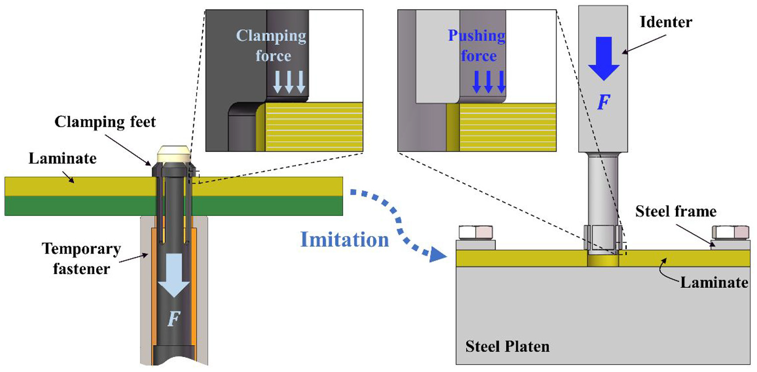
Design idea of copying indenters.
To perform QSI experiments, it is necessary to produce a profiling indenter with accurate geometry and sufficient hardness. The key dimensions of the clamping feet of temporary fasteners are millimeters and sub-millimeters, so the VGS Flexi 3000 imager was selected to measure them. The measurement accuracy is (3 + L/200) μm, where L is the measured length. According to the measured data, the copying indenters that are consistent with the bean-shaped, cone-shaped, and cylinder-shaped clamping feet are respectively processed (Figure 3). In order to ensure performance, the material of the indenter is SKD-11 die steel, which has been vacuum quenched to improve the surface hardness. The test results show that the surface hardness of the indenter after heat treatment is 60HRC.
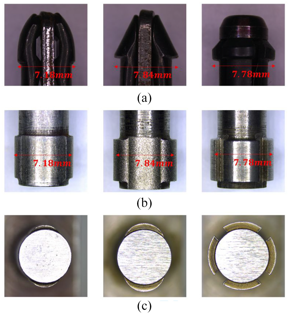
Copying indenters: (a) clamping feet of temporary fasteners (front view), (b) copying indenters (front view), and (c) copying indenters (axis view).
QSI tests
The QSI tests are carried out on the microelectronic universal testing machine. Refer to the literature 24 to design a quasi-static indentation fixture (Figure 4). The threaded hole on the stage is used to clamp the composite sample, and the indenter is installed in a tightening mechanism for replacement. The model of the microelectronic universal testing machine is SHENZHEN SUNS UTM5504, the maximum pressure that can be applied is 25 kN, the force accuracy is ±0.24%, and the displacement accuracy is ±0.17%. During the experiment, a laser extensometer is used to measure the pressing distance of the indenter. The QSI tests are carried out to realize the gradual loading under the displacement control mode, and the loading rate is 0.5 mm/min.
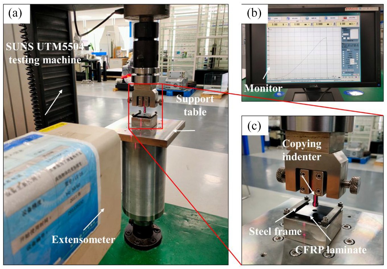
Experimental device of QSI tests: (a) experiment platform, (b) monitor, and (c) compression fixture.
Design of experiments
Clamping feet type, prepreg category, and installation direction are the main factors that affect temporary fastening damage. Different types of clamping feet have different contact areas with the laminate, which makes the clamping force that the composite hole can bear significantly different. Whether the ability of the laminate to resist the intrusion of the indenter is related to the transverse compressive strength of the prepreg, the stacking sequence, and the installation direction of the clamping feet remains to be further explored. Therefore, the DOE in this article is shown in Tables 2 and 3, and a total of six sets of experiments are required.
Factors within the experiments.
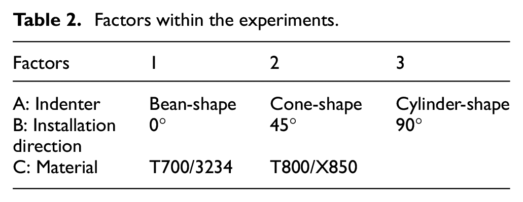
Design of experiments.
Results and discussion
Similarity verification
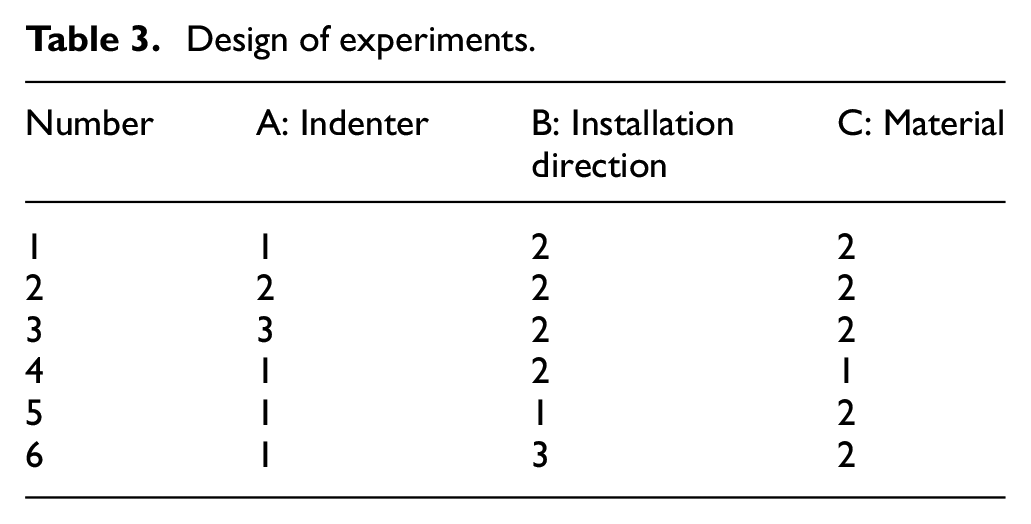
A comparative analysis of the temporary fastener installation experiment and the QSI experiment is carried out. Figure 5(a) shows the installation damage diagram of the bean-shaped temporary fastener. The installation tool is Ingersoll Rand-W500-30-931-GB, the installation air pressure is 0.7 MPa, and the clamping force is 2282 N. Figure 5(b) shows the hole damage from the quasi-static indentation to the initial acoustic emission of the specimen, and the maximum load is 2348 N. It can be seen from the figure that for the cone-shaped clamping foot, there is a crescent-shaped matrix crush area around the composite hole. Its length is 7.13 and 7.19 mm, width is 3.14 and 3.21 mm, depth is 0.15 and 0.16 mm, and the maximum size of delamination damage is 9.49 and 10.32 mm respectively. Quasi-static indentation damage and temporary fastener installation damage show a strong similarity in form and size. Therefore, it is feasible to simulate the installation of temporary fasteners through the quasi-static indentation experiment around the hole. The quasi-static indentation experiment brings great convenience to the study of temporary fastening damage.
Comparison of temporary fastener installation and QSI experiment: (a) optical observation of installation damage of temporary fastener, (b) optical observation of QSI damage, (c) ultrasonic microscopic observation of installation damage of temporary fastener, and (d) ultrasonic microscopic observation of QSI damage.
Load response
Laminates respond differently to the intrusion of different types of indenters. The solid line in Figure 6 shows the typical indentation pressure and penetration depth response of a T800/X850 laminate with a hole diameter of H = 6.38 mm and a thickness of L = 3.45 mm under a bean-shaped indenter load of 0.5 mm/min. When the indentation depth is before 0.2 mm, the load increases nonlinearly with the depth h. This includes the plastic flow of the resin on the surface of the laminate and the closure of the thickness gap. Then the load increases linearly with the displacement, until the load F = 1950 N, the laminate starts to appear delamination damage at the edge of the indenter, which is consistent with the phenomenon observed by Jorgensen et al. 7 When the indentation load reaches 2348 N, severe damage occurs around the hole. This damage is high-energy, accompanied by a sudden drop in load and greater acoustic emission. The surface of the laminate around the indenter is warped at this time, and the indenter is embedded in the laminate. The load-intrusion depth response of the cone-shaped indenter and the cylinder-shaped indenter is shown by the dotted and dashed lines in Figure 6(a), respectively. Similarly, before the indentation depth of 0.2 mm, the load increases nonlinearly with the depth h. Subsequently, when the load F = 4141 N and F = 12,442 N, the laminates showed strong damage at the edges of the conical indenter and the cylindrical indenter, which was also accompanied by a sudden drop in load and greater acoustic emission. Therefore, it can be determined that for the hole of H = 6.38 mm, under the action of the three clamping feet, the maximum clamping force that can be carried is 2348, 4141, and 12,442 N, respectively.
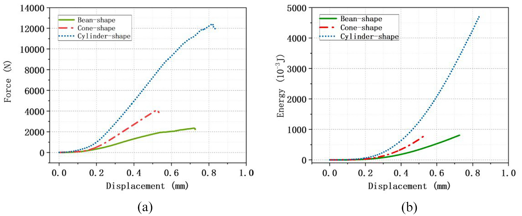
The indentation force and cumulative work are plotted as functions of displacement: (a) displacement-load curves of three indenters, and (b) displacement-energy curves of three indenters.
Integrate the load-displacement curve to get the energy required for the failure of the composite material. The calculation formula is:
It can be seen from Figure 6 that the maximum energy required for the damage of the composite material caused by the cylindrical indenter is W = 4.53 J, for the punch to penetrate h = 0.822 mm. The total energy required by the bean-shaped indenter is similar to that of the cone-shaped indenter. The energy required by the bean-shaped indenter is W = 0.796 J, for the punch to penetrate h = 0.721 mm. And the energy required for the cone-shaped indenter W = 0.769 J, for the punch to penetrate h = 0.524 mm. Since the maximum penetration depth of the bean-shaped indenter is larger than that of the cone-shaped indenter, it can be judged that the damage caused by the bean-shaped indenter to the composite board is more complicated.
Damage behavior and mechanism
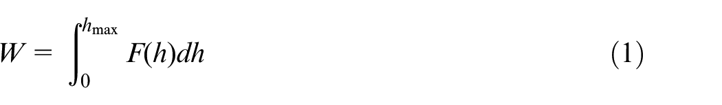
The thickness loading of the indenter caused serious damage to the composite hole. Figure 7(a) shows the optical micrograph of the composite hole when the bean-shaped indenter is loaded to 2348 N. The indenter left the pits of the same shape as the indenter around the composite hole. Fiber fracture and matrix crushing were observed in the pits, and neat fiber fracture bands appeared on the edges of the pits, which is similar to the literature. 8 The indentation of the indenter causes the surface material on the outer edge of the indenter to warp upward, so serious delamination is expected. The results of the ultrasound scan confirmed this, and delamination occurred from just below the indenter to the farthest 1.2 mm range. The intrusion of the indenter leads to the intrusion of the fibers and the matrix into the adjacent non-compressed area, resulting in bulging of the surface layer.
Damage observation of composite holes: (a) damage of composite hole under bean-shaped indenter, (b) damage of composite hole under cone-shaped indenter, and (c) damage of composite hole under cylinder-shaped indenter (the pictures from left to right are optical micrographs of composite block damage, optical micrographs of fiber fracture zone, and ultrasonic scanning micrographs).
Figure 7(b) and (c) show the optical micrographs of the composite hole of the cone-shaped indenter and the cylinder-shaped indenter at maximum load. Obviously, pits consistent with the shape of the indenter appeared around the composite hole, and white marks (in white boxes) appeared on the edges. On the outside of the pit, a large area of delamination occurred between the layers, and the delamination expanded along the fiber direction. Because the deformation of the composite material directly under the indenter is relatively consistent, it remains relatively intact, and no delamination damage is found in ultrasonic testing.
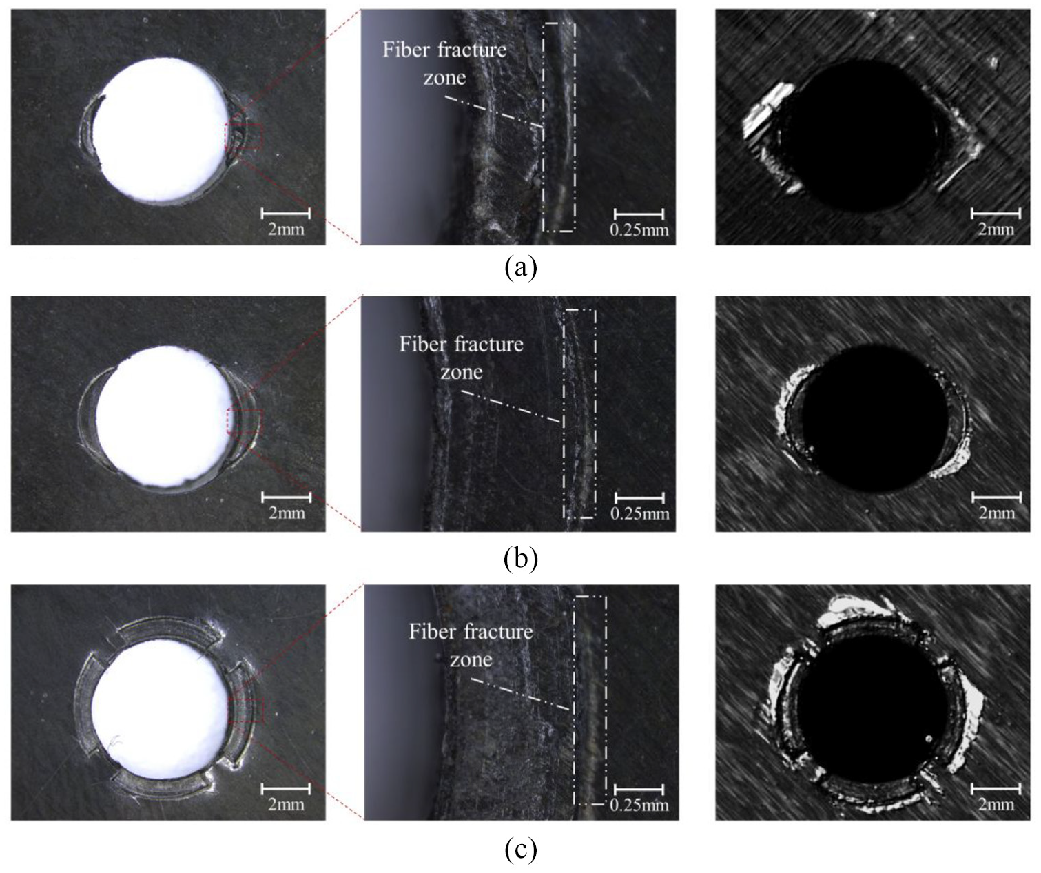
The pits were measured using a confocal laser microscope (Figure 8). The depth of the pits formed by the bean-shaped indenter is 0.168 mm, and the depths of the pits formed by the cone-shaped and cylinder-shaped indenters are approximately 0.067 and 0.071 mm, respectively. It can be seen that after the indenter retracts, the pit has elastically recovered.
Confocal laser observation of pits: (a) confocal laser scanning observation of bean-shaped clamping feet damage, (b) confocal laser scanning observation of cone-shaped clamping feet damage, (c) confocal laser scanning observation of cylinder-shaped clamping feet damage, and (d) Shows Uz as a function of X-position.
O’Masta et al. 8 think that when the back is supported, the fiber indirect tensile fracture occurs in the laminate under the compressive load in the thickness direction. However, this article believes that when the load is applied to the periphery of the hole, the shearing effect of the indenter edge should be dominant due to the low stiffness of the material around the hole wall. This also explains why in the damage observation images of the three indenters, we have found fiber fracture zones consistent with the outer contour of the indenter. Due to the retreat of the material directly below, a height difference appears on both sides of the edge of the indenter, and interlayer peeling occurs first. When the indenter is further loaded, the shear stress of the laminate at this place will further increase until it is greater than the shear strength of the fiber, so that the fiber will undergo shear fracture. At this time, the pavement structure collapsed, strong acoustic emissions were emitted, and the load dropped suddenly.
Therefore, the QSI damage process around the composite hole can be divided into three stages on the basis of Yu et al. 10 elasticity, delamination, and failure (Figure 9). In the elastic stage, the material directly under the indenter first undergoes elastoplastic deformation. At this time, the composite material is not damaged, and the indenter will only leave an indentation on the resin on the surface after it is returned. In the delamination stage, the pressure continues to increase, and the stress and deformation of the composite material also increase further. Due to the relative displacement trend between the layers, the edge of the indenter begins to layer along the fiber direction and continues to expand as the pressure increases. In the failure stage, while the matrix under the edge of the indenter is cracked, the surface fiber is sheared and fractured. In the area close to the outside of the indenter, the composite surface appears partially warped and accompanied by the sound of splitting. At this time, a larger area of delamination occurs between the first layer and the second layer of the composite material.
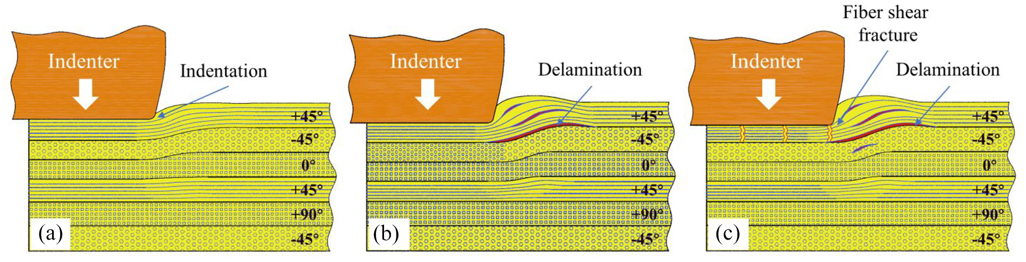
Three stages of QSI damage around the composite material hole: (a) elastic stage, (b) delamination stage, and (c) failure stage.
Effect of materials
As shown in Figure 10, when the bean-shaped indenter is used for quasi-static indentation, a similar conformation makes the hole damage appear in a similar pattern. However, the performance of T800/X850 laminates is 18.8% higher than that of T700/3234 in resisting the intrusion in the thick direction. This is attributed to the difference in the properties of materials, 25 high tensile strength carbon fiber has good toughness to spread to high energy absorption capacity, resulting in better resistance to intrusion and damage tolerance.
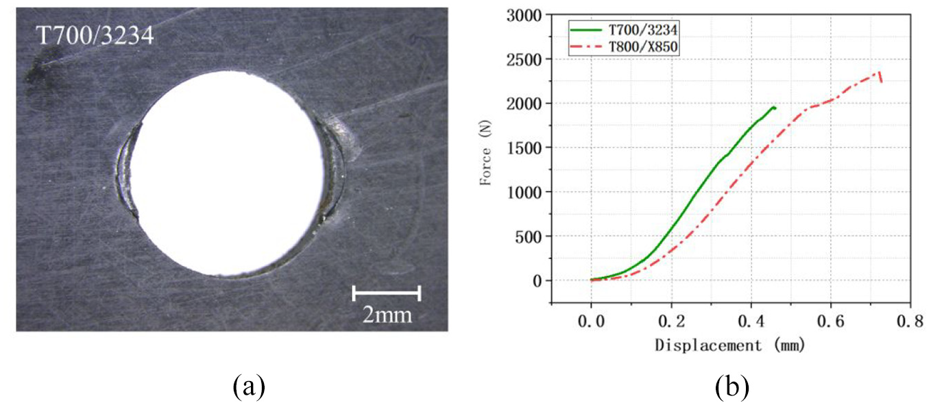
The influence of materials on the resistance to intrusion: (a) optical observation of T700/3234 and (b) comparison of the displacement-load curve.
Anisotropy
There is a significant difference in the thickness resistance ability of the composite material around the hole in all directions. Figure 11(a) shows the damage diagram around the hole when the angle between the indenter and the surface fiber direction is 0° and F = 1598 N. Figure 11(b) shows the damage diagram around the hole when the angle between the indenter and the surface fiber direction is 90° and F = 2470 N. It can be clearly seen that when the indenter is parallel to the fiber direction, the anti-intrusion ability of the composite material is significantly reduced by 35.3% compared to when the indenter is perpendicular to the fiber. Although their appearance damage is similar, the ultrasonic test results show that when the indenter is parallel to the fiber direction, the interlayer peeling occurs on the outside of the indenter under a small load. However, when the indenter is perpendicular to the fiber direction, the layered area expands in the fiber direction under a larger load. This is a completely different form of influence from the fiber stacking direction proposed in Ahmad et al., 26 O’Masta et al., 27 and Fotouhi et al. 28 It is conceivable that when the indenter intrudes, the fiber in the 0° direction is similar to a cantilever beam, which is prone to fiber shear fracture. The fibers in the 90° direction are more like fixed beams and can better resist intrusion. Figure 12 calculates the energy required by the indenter in the three directions before acoustic emission. Among them, the energy required for the 0° direction is the smallest, W = 0.258 J, and the energy required for the 45° and 90° directions is approximately 3.2 times that of the 0° direction.
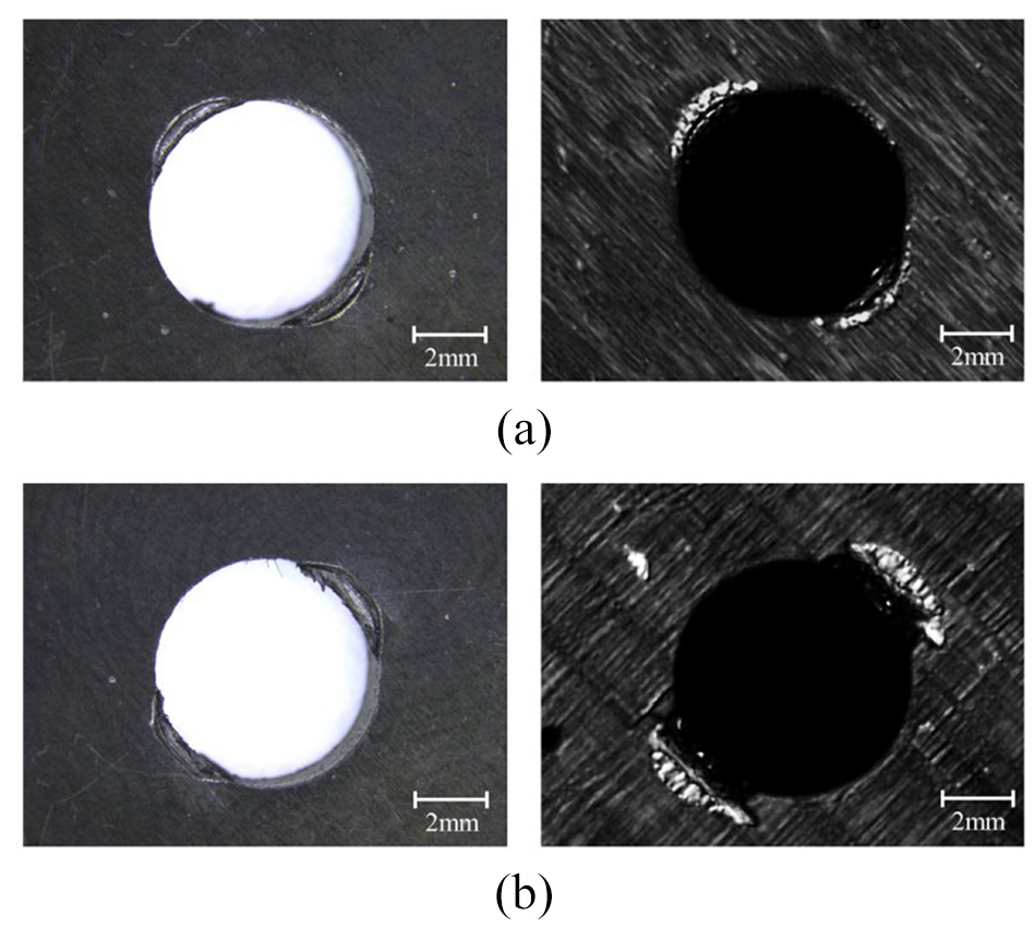
The influence of installation directions on the resistance to intrusion: (a) composite hole damage in 0° installation direction and (b) composite hole damage in 90° installation direction.
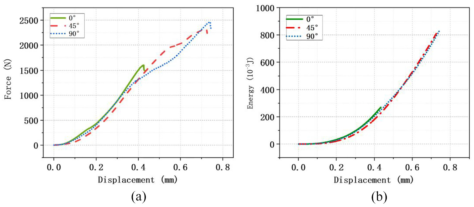
Force-displacement curve of different installation directions: (a) displacement-load curves of three installation directions and (b) displacement-energy curves of three installation directions.
Conclusion
In this paper, copying indenters are designed according to the shape of the temporary fastener clamping feet. The quasi-static indentation experiments were used to investigate the influence of clamping feet, composite material type, stacking sequences, installation direction, and other factors on the damage of composite holes. The damage morphologies were observed with an optical microscope and ultrasonic microscope. The following conclusions are obtained:
The designed copying indenter can well simulate the clamping process of temporary fasteners. The quasi-static indentation experiment can be used to study the temporary fastening damage during the assembly process of aviation composite materials, so as to obtain the detailed damage conditions at each stage of the loading process. This method can also be used to determine the maximum pre-tightening force of bolts, rivets, and self-tapping screws in composite structures.
During temporary fastening, the damage process around the composite material hole can be divided into three stages: the first is the elastic stage, the composite material will not be damaged and only a shallow indentation will appear on the surface resin. The second is the delamination stage, delamination appears along the fiber direction at the edge of the indenter and continues to expand as the pressure increases. The last is the failure stage, interlayer peeling, matrix crushing, and fiber shear fracture occurred at the same time.
The resistance of laminate to intrusion in the thickness direction is affected by the material and fiber direction. The composite hole has the weakest resistance to intrusion from the thickness direction in the fiber direction. When studying the temporary fastening process, the fiber direction should be used as the installation direction of temporary fasteners to ensure the reliability of the results.
Footnotes
Declaration of conflicting interests
The author(s) declared no potential conflicts of interest with respect to the research, authorship, and/or publication of this article.
Funding
The author(s) disclosed receipt of the following financial support for the research, authorship, and/or publication of this article: This work is supported by the National Natural Science Foundation of China (Grant No.51775350).