
Abstract
The friction stir spot welding (FSSW) process is one of the main solid-state joining methods used widely for welding different materials and dissimilar metals. In this article, the welding of Polytetrafluoroethylene (PTFE) and aluminum alloy sheets by the FSSW process will be investigated experimentally. The joining of polymer (PTFE) and metal (AA1050 aluminum alloy) was done successfully. The effect of process parameters including tool rotational speed, penetration depth, initial holding time, dwell time, and tool shoulder diameter on the joint strength and elongation of the weldments will be studied using response surface methodology (RSM). The joint strength was increased by creating a threaded hole in the aluminum sheet. A mechanical lock was created between the softened PTFE and the edge of the threaded hole. The shear-tensile tests have been carried out for 32 designed experiments. The results show that the joint strength increased by increasing the initial holding time due to the better wettability of PTFE and aluminum sheet. The joint strength increased by increasing the tool rotational speed and tool diameter (better pouring of the hole and formation of the mechanical lock). Two different fracture modes have been observed in the samples: (1) fracture in the peripheral area of the joint (partial interfacial fracture mode) and (2) fracture in the mechanically locked area (pull-out mode with tearing).
Graphical abstract
Introduction
Welding of dissimilar alloys helps to manufacture lightweight structures with desired properties and performances. In automotive industries, one of the main challenges is welding different grades of aluminum alloy to each other. Friction Stir Welding (FSW), Resistance Spot Welding (RSW), and Gas Tungsten Arc Welding (GTAW) process are three standard welding processes used widely for joining of dissimilar alloys and materials. Polymers are one of the types of materials which has different material properties compared to metals. Lower density, higher elongation, low melting temperature, and low electrical conductivity are the main mechanical and physical properties of polymers compared to metals. The joining of polymers is constrained due to very low electrical conductivity, So, the joining of polymers usually happened by local warming up to 250°C. Adhesive bonding is another way of polymer joining. Among these, the dissimilar joining of polymers and metals has great attention and industrial applications. The polymer-metal joint can have several advantages, such as weight reduction and enhanced corrosion resistance. The main problem in joining is the different bonding mechanisms of metals (metallic bonding) and polymers (van der walls bonding of monomers). The heat source required for welding should provide a low magnitude and controllable heat to soften the polymer, mix the softened polymer in the nugget zone, and at last create bonding between the polymer and metal. The metals transfer the heat quickly, while the polymers have low thermal conductivity. Among the welding processes, friction-based welding can provide the required specification of the heat source. The friction stir spot welding (FSSW) process is economically sound compared to the resistance spot welding process. The FSSW process is a friction-based welding process that got the authors’ attention to join the polymer and metals.
Friction Stir Spot Welding (FSSW) and Friction Stir Welding (FSW) are two typical solid-state welding processes. Welding at temperatures below the melting point leads to the fabrication of the joints without embrittlement, thermal cracking, and distortions. The FSSW can be used in many industries such as automobile, aerospace, shipbuilding, and railway industries. The FSSW process is a highly energy-efficient and cost-effective spot welding technique compared to other spot welding processes. 1
Bozkurt and Bilici 2 investigated the effect of plate positioning on mechanical properties of dissimilar AA2024-T3 and 5754-H22 aluminum alloy sheets by the FSSW process. The optimized condition of welding was obtained by implementing nine experiments designed according to the Taguchi orthogonal array. The maximum fracture load value was obtained using 1500 rpm rotational speed, 2° tilt angle, 2.65 mm tool plunge depth, and 10 s dwell time while the AA2024-T3 sheet was placed above the AA5754-H22 aluminum sheet. Jambhale et al. 3 investigated the effect of FSSW process parameters such as tool tilt angle, tool rotational speed, dwell time, and tool pin profile in welding of AA6082-T6 and AA6061-T6 aluminum alloys using Taguchi orthogonal array design. The analysis of variance (ANOVA) results shows that increasing tilt angle, increasing tool rotational speed, increasing dwell time, and cylindrical threaded pin profile lead to higher joint strength. A similar study was conducted by Shen et al. 4 for AA6061-T4 aluminum alloy and Shekhawat et al. 5 for AA6061 aluminum alloy. The rotational speed played a crucial role in joint strength. 4
Silva et al. 6 studied the effect of process parameters (rotational speed, feeding rate, and plunge depth) on the weld strength of AA6082-T6 aluminum alloys by Refill Friction Stir Spot Welding process using one-factor at a time (OFAT) statistical tool analysis. Also, the formation of a hook in the welding region is investigated by analyzing the microstructure. De Castro et al. 7 studied process parameters’ effect includes the tool rotational speed, welding time, and tool plunge depth, using the Taguchi method. Also, a new refill tool was designed and fabricated. The developed tool leads to an increase in the effect of plunge depth on the welding property. Several explorers about the refill-FSSW process were conducted by researchers.8,9
Suryanarayanan and Sridhar 10 investigated the joining of dissimilar AA5754–AA6061 aluminum alloy sheets by the FSSW process according to experiments planned by Response Surface Methodology. Maximum weld strength of 6 kN was obtained at 1000 rpm and 0.04 mm/s plunge speed. The tool rotational speed was the most influential process parameter that affects the tensile shear force of the weld joint. Suryanarayanan and Sridhar 11 published a comprehensive review paper and discussed different types of FSSW processes and the effect of process parameters. The results show that an increase in tool rotational speed, time, or plunge depth increased the hook height and resulted in lower weld strength. 12
Shen et al. 13 studied the welding of Al 6022-T4 and Al 7075-T6 aluminum alloy (dissimilar parts) by refill FSSW process. The material flow due to the back extrusion and forging creates a mechanical locking. The results show that the mixing of materials happens during the sleeve’s retraction period, not in the plunging period of the sleeve. Bilici and Yükler 14 studied the effect of six different tool pin profiles (straight cylindrical, tapered cylindrical, threaded cylindrical, triangular, square, and hexagonal) to weld polyethylene sheets. The experiments show that the tapered cylindrical pin profile can produce maximum joint strength (average force of 3580 N). In contrast, the straight cylindrical pin profile gave the lowest strength (average force of 2820 N). Gao et al. 15 studied the welding of thermoplastic polyimide by friction stir spot welding (FSSW). The results show that increasing the dwell time could increase the mixing time and reduce the viscosity of the material, which made the structure was denser. The maximal shear strength was obtained 85.5% of the base materials. It was indicated that FSSW had a feasible and potential technology to join the high-temperature resistant engineering plastics. Sahu et al. 16 investigated the joining of different thermoplastic materials includes polycarbonate and nylon-6 sheets using friction stir welding (FSW). Various tool pin profiles (cylindrical, square, and triangular) are tested. A higher axial force with reduced torque has been observed for nylon-6 as compared to polycarbonate. Best joint strength had been obtained at tool rotational speed 1800 rpm and welding speed 20 mm/min using square tool pin profile.
Yusof et al. 17 studied the joining of polyethylene terephthalate (PET) as a high-density thermoplastic sheet and AA5052 aluminum sheets by friction spot welding (FSW) process. During the FSW process, the PET near the joining interface softened, partially melted, and adhered to the A5052 joining surface. The formation of bubbles is produced due to PET evaporation in the contact zone. The results show that increasing the surface roughness can enhance the joint strength considerably due to the formation of mechanical interlocking. Bang et al. 18 investigated the friction stir welding of polyamide 66 (PA 6.6) CFRP and AA5052 aluminum alloy sheets using pinned and pin-less tools. The results show that the pin-less tool and surface ground aluminum alloy can fabricate an appropriate joint with maximum joint strength of about 8 MPa. Kumar et al. 19 studied the welding of composite sheets with the FSSW process. The welded sheets were prepared by 3D printing from ABS thermoplastic+ 15%wt aluminum alloy powder. The used tool was not solid and non-consumable; the tool was prepared from polyamide (PA)6 reinforced with 50% wt. Aluminum alloy powder. The influence of input process parameters (rotational speed, plunge depth, and stirring time) was investigated by Taguchi’s design of experiments. The optimized condition for welding was obtained, and the tensile test results show that the tensile properties of ABS-15Al joints prepared by FSSW are comparable to virgin ABS. Adibeig et al. 20 used the friction stir spot welding process and adhesive bonding simultaneously for joining polyethylene plates. Taguchi design of experiment was employed to investigate FSSW parameters’ effects (tool rotational speed, dwell time, and plunge rate) on the joint strength. The joint’s strength increases about 30% by adding adhesive. The results show that the dwell time has a more significant effect than the other two parameters.
Pramanik et al. 21 published a review paper and comprehensively discussed different mechanisms and mechanical properties of joining CFRP and aluminum alloys. Various methods of joining consist of the use of adhesive, self-piercing rivet, bolt, clinching, and welding. Except for adhesive bonding and welding, other joining methods require the penetration of metallic pins through joining parts, and therefore, surface preparation is unimportant. Pragana et al. 22 investigated the joining of two metal-polymer sandwich composite panels at the perpendicular position. An innovative three-stage solution comprising cutting out the polymer core of the tenon placed above the surface of the mortise followed by nosing and flat punch upsetting of the outer thin metal sheets of the tenon is capable of producing mechanically locked joints with larger and stiffer flat-shaped heads. The forming forces are below 15 kN, which is an effective alternative to existing solutions based on adhesive bonding, welding, and mechanical fastening.
Jamili-Shirvan23,24 investigated the joining of Ti-based bulk metallic glass by friction stir spot welding (FSSW) process. The results show that the stir zone under the tool shoulder has the highest micro-hardness (9.82 GPa), the largest elastic modulus (139.95 GPa), and the smallest amount of plastic deformation.
Bhardwaj et al. 1 and Suryanarayanan and Sridhar 11 published review papers and discussed more aspects of the FSSW process. The literature survey shows that the friction stir spot welding process can weld different materials and dissimilar joints. Most of the researches has been focused on the welding of metals. There are few studies about the welding of polymer and metal; most of them concentrate on polymer matrix composites. Though in this article, the welding of AA1050 aluminum alloy parts with Polytetrafluoroethylene (PTFE) parts will be carried out experimentally, and the joint strength will be investigated using the design of experiments (DOE) planning. For this purpose, the effects of process parameters such as tool rotational speed, initial holding time, dwell time, tool diameter, and penetration depth of a flat tool on the joint strength will be probed by a statistical tool. The work’s main novelty is joining polymer and metal, considering process parameters’ effectiveness to maximize the joint strength. Compared to the previous studies, using the DOE technique can determine the majority of process parameters includes the interaction of the parameters which was not employed in the FSSW process investigation.
Materials and methods
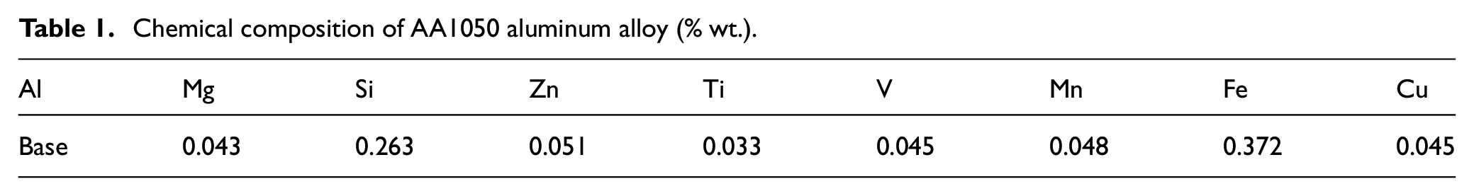
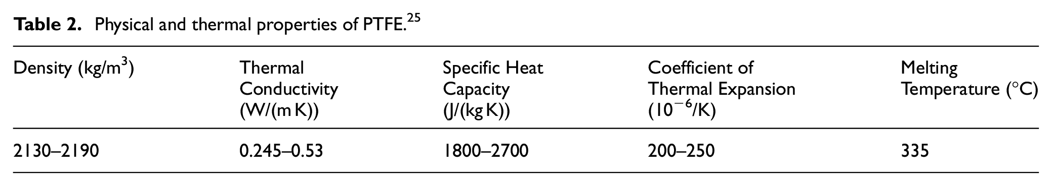
In this article, the welding of AA1050 aluminum alloy parts with Polytetrafluoroethylene (PTFE, Teflon) parts will be investigated. The PTFE polymer is a thermoplastic polymer. The friction stir spot welding (FSSW) process will be utilized for joining. Using the FSSW process in polymer joining is rare and in developing stages. The aluminum parts are prepared by cutting (sawing). The thickness of aluminum parts is 1 mm, and the thickness of PTFE is 5 mm. Table 1 shows the chemical composition of AA1050 aluminum alloy obtained from optical emission spectrometry (quantometer). Table 2 reports the physical and thermal properties of PTFE.
Chemical composition of AA1050 aluminum alloy (% wt.).
Physical and thermal properties of PTFE. 25
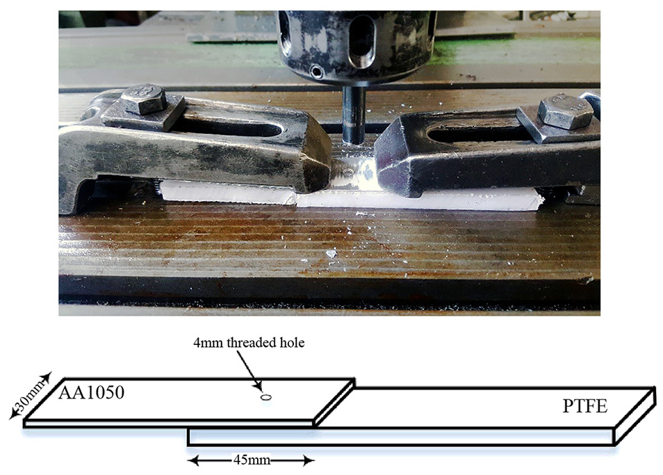
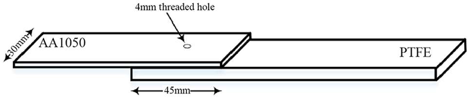
The parts are welded according to Figure 1 configuration. The overlap area of the aluminum part and PTFE part is 30 × 45 mm2 dimensions. The condition of the surface is essential in joining. Any dust, grease, or surface contamination can affect the joining quality. The surfaces of aluminum parts are prepared by cleaning with acetone and sandpaper before joining. The PTFE samples were washed with acetone carefully. The rotational speed of the tool is prepared by using an FP4ME milling machine. The tool is prepared from H13 tool steel (14 mm diameter, no pin). The tool will experience a high temperature and high frictional and wear conditions. The hot work tool steel is a suitable material for the described operational conditions. The heat treatment of the tool is essential. A quenching and a subsequent tempering process are used in tool preparation. Two slotted strap clamps fixed the aluminum part and PTFE part, and the friction stir spot welding has been carried out with different rotational speeds, different penetration depths, and dwell times. A Design Of Experiments (DOE) plan has been used for experimentation. Figure 2 shows the experimental setup used for performing the FSSW process and one of the welded specimens.
Schematic view of friction stir spot welding process.
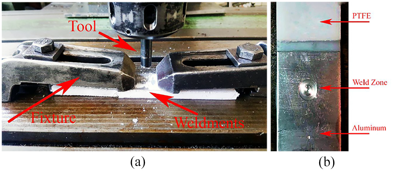
(a) The configuration of friction stir spot welding and (b) welded sample.
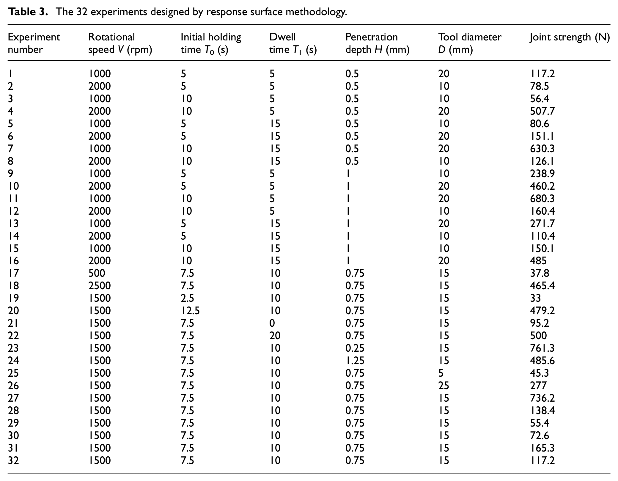
Response Surface Methodology (RSM) is one of the conventional design of experiments methods used widely for experimentation. In this study, the aim is to identify and determine the effect of input parameters on the output parameter. The statistical analysis shows that the mean surface response (MSR) of the input variable. So, RSM is a powerful tool for investigation. In this method, the interaction of process variables is involved in the study, and the response surface diagram shows the interaction of process parameters. Two forms of RSM exist, Box-Benken and Central Composite Design (CCD). In this article, the CCD method was used for the design of experiments. According to the literature survey, the experimental process parameters in the FSSW process are rotational speed V, penetration depth H, tool diameter, pin diameter, head type of pin, initial holding time and dwell time, penetration speed. In this study, five process parameters are selected for experimentation, and the others are considered constant parameters. Rotational speed V, the penetration depth H, initial time of tool rotation for heating and softening (holding time at the start of the process), T0, dwell time at the final depth T1, and the tool diameter D is the process parameters of the FSSW process. Table 3 shows the 32 experiments designed to investigate joint strength (shear lap force) and elongation. Minitab Software schedules the 32 experiments. The selected range of process parameters is determined according to the machine specifications (the available capacity of rotational speed) and typical process parameters used in the literature. Pre-tests have been conducted to assure the possibility of welding. It is necessary to fabricate a wholly bonded weldment to analyze the results of the RSM method. Separation of PTFE and aluminum alloy is not accepted.
The 32 experiments designed by response surface methodology.
The aluminum part is drilled and threaded by an M4 threading tool. The hole helps mechanical locking of materials and increases the joint strength considerably. Pre-tests show that the joint is very weak without creating the threaded hole. The head of the tool is straight, and no pin exists.
The shear-tensile tests have been carried out for the designed 32 experiments successfully. Figure 3 shows the implementation of the shear-tensile test. The tensile-shear force of the laser-welded joints was assessed according to the ASTM E8/E8M 26 standard. The tensile tests were carried out at a constant loading rate of 1 mm/min (∼1.5 × 10⁻⁴ 1/s average strain rate).
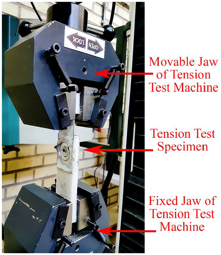
The shear tensile test.
Results and discussion
Shear-tensile test results
The results of tensile tests (average joint strength) were shown in Table 3. Table 4 shows the ANalysis Of VAriance (ANOVA) results for maximum force obtained from the results of the shear-tensile tests (with 95% confidence value). The p-Value column shows the significance of the parameters. If the p-Value was greater than 0.05, the parameter is insignificant and for lower values than 0.05, the parameter is significant. By obtaining the ANOVA results, it is possible to assess the order of significance of process parameters in the Pareto chart. Figure 4(a) shows the Pareto chart of all process parameters and the process parameters’ interaction. As can be seen, many process parameter interactions have little effect on joint strength and can be neglected. By terminating some of them, the modified Pareto chart can be seen in Figure 4(b). The importance and effectiveness of process parameters can be seen obviously. The tool diameter is the most influential process parameter, and the square of penetration depth H2 and initial holding time T0 are the second and third significant process parameters.
The analysis of variance results obtained from statistical analysis.

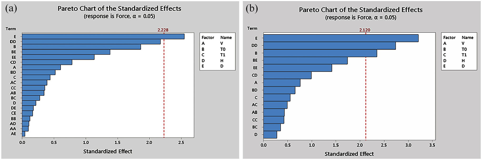
Pareto chart for analyzing process parameters and its interaction: (a) full model and (b) modified model.
The joint strength (fracture force) of welded specimens can be expressed according to equation (1). Equation (1) was driven according to fitting a full-quadratic equation (considering all process parameters) to the results with regression methods. By excluding the insignificant process parameters from ANOVA results, Equation (2) can be obtained for selected influential process parameters.
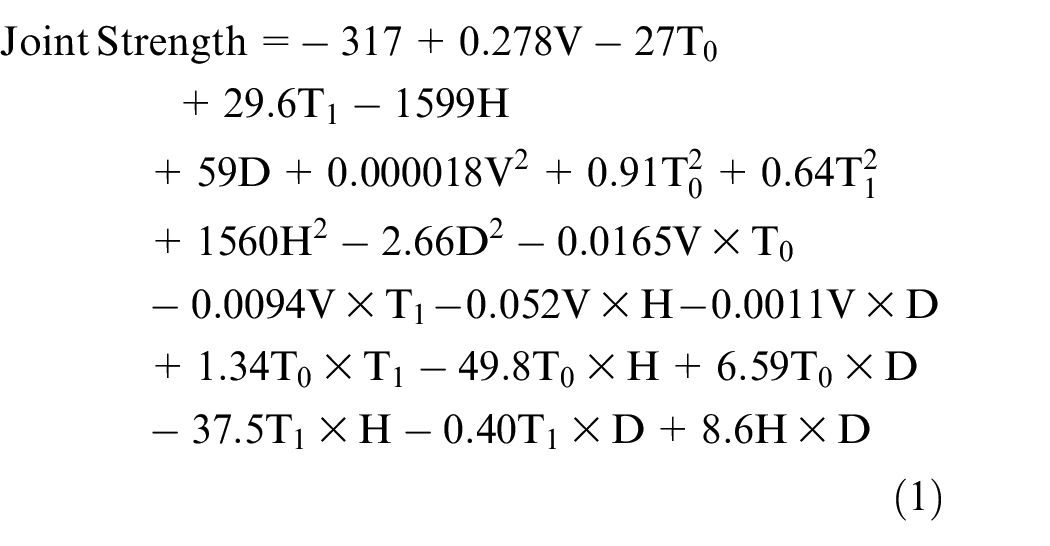

Figure 5 shows two shear-tensile test specimens with different fracture modes. In some samples, fracture modes similar to Figure 5(a) were observed, which shows that the welding is weak, and only a weak joint is created between PTFE and aluminum sheet. This mode is called partial interfacial fracture mode and is mainly observed at low rotational speeds. In other cases, like Figure 5(b), the fracture happens in the aluminum sheet, and part of the aluminum adhered (joint) to the PTFE completely, which is called pull-out mode with tearing. The mechanical locking is complete, and the softened PTFE filled the inner 4 mm threaded hole of the aluminum sheet. The tool penetration depth and the rotational speed are high and produce sufficient heat for adhering to the PTFE and aluminum sheets. The heated-up zone of PTFE is high.
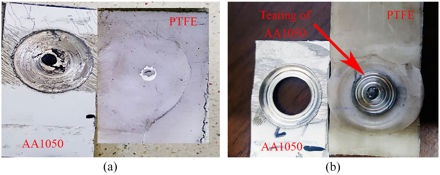
Two different fracture modes were observed in welded specimens: (a) partial interfacial mode and (b) pull-out mode with tearing.
Effect of process parameters
The FSSW process is carried out according to the design of experiments (DOE) planning. The process variables vary in all 32 investigations, but the effect of individual process parameters can be assessed by statistical tools prepared by variance and covariance. Figure 6 shows the effect of five process parameters independent of each other.
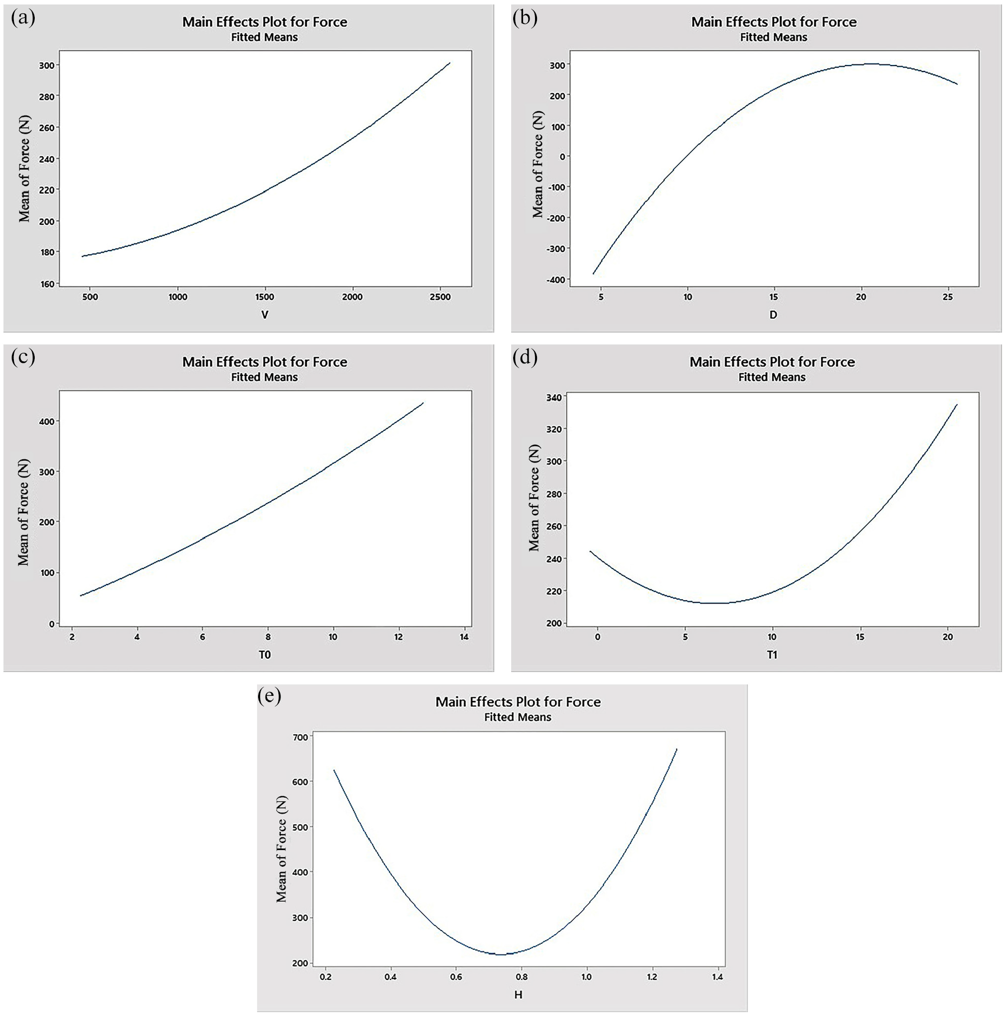
Mean effect plot for variation of force by: (a) tool rotational speed (V), (b) tool diameter (D), (c) initial holding time (T0), (d) dwell time (T1), and (e) penetration depth (H).
Figure 6(a) shows that by increasing the tool rotational speed, the joint strength increases. The increase is not linear, and the increase in the joint strength is much higher. Increasing the tool rotational speed leads to higher heat generation due to frictional movement, and a higher volume of PTFE softens, and the wettability of PTFE increases. The higher temperature extrudes the PTFE from the central hole. After retarding the tool, the extruding of PTFE continues, so a mechanical locking will create between the PTFE and aluminum sheet after cooling. The fracture mode is usually pulled out mode with tearing.
Figure 5(b) shows the effect of the tool diameter. The results show that the joint strength increases by increasing the tool diameter up to about 20 mm. But for larger diameters than 20 mm, the joint strength decreased. This decrease in joint strength is due to higher generated heat in frictional movement, which leads to increasing the temperature of PTFE so that it flows out from the welding zone. The increase in the temperature reduces the viscosity of PTFE, and the subsequent softening flows out the material freely.
Figure 6(c) shows that by increasing the initial holding time T0, the PTFE softens more due to higher heat generation and heat transfer by the aluminum part. The joint strength enhances subsequently. The authors’ other experience shows that increasing the initial holding time (e.g. T0 = 30 s) will not increase the joint strength. When the peripheral PTFE material softens, increasing the time did not produce extra heat generation, and the frictional heat will not increase. Also, the manufacturers did not prefer a long manufacturing time. The threaded hole fills better by increasing the initial holding time, and mechanical locking of PTFE and aluminum sheet formed more effectively.
Figure 6(d) shows the effect of the dwell time T1. The results show that the joint strength decreases by increasing the dwell time at first, and then the joint strength will increase by increasing the tool diameter for dwell time higher than 8 s. The low dwell time did not allow the softened PTFE to extrude through the threaded hole while increasing the dwell time allows for flowing out the softened PTFE from the central hole. Better mechanical locking will be obtained by increasing the dwell time. Also, the tensile test results show that increasing the dwell time improves the joint’s elongation, and pulling out with tearing fracture mode happens.
The effect of penetration depth H on FSSW joint strength was shown in Figure 6(e). The results show that the joint strength decrease by increasing the penetration depth up to 0.75 mm. The joint strength increases for penetration depth higher than 0.75 mm. By increasing the penetration depth from a specific limit, part of the sheet penetrates in the PTFE, and after retarding the tool, the compressed softened PTFE flows out from the central hole and makes a mechanical lock. This is why the fracture modes vary from partial interfacial mode to pull-out mode with tearing.
Interaction of process parameters
Figure 7 shows the interaction of rotational speed V and initial holding time T0 for the hold value of T1 = 10 s, H = 0.75 mm, and D = 15 mm. The response surface shows that increasing the rotational speed and initial holding time simultaneously will not increase the joint strength.
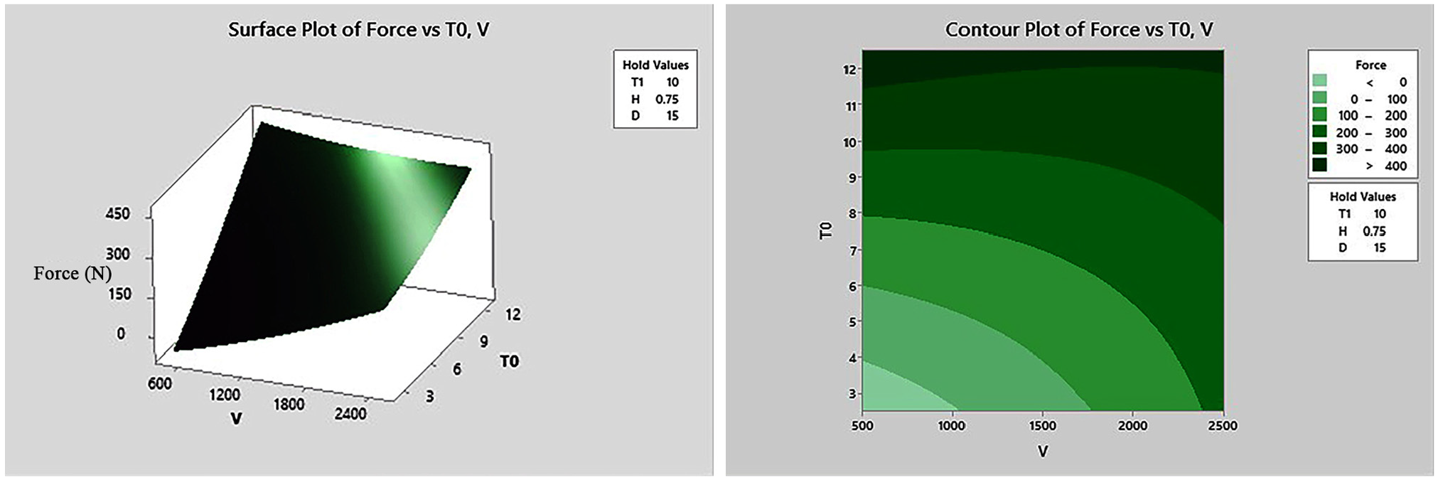
Response surface plot for variation of force by tool rotational speed (V) and initial holding time (T0).
Figure 8 shows the interaction response of rotational speed and dwell time T1 at a specified condition (T0 = 7.5 s, H = 0.75 mm, and D = 15 mm). The response surface shows that at low rotational speed, increasing the dwell time leads to an increase in joint strength. But at higher rotational speed, the effect of dwell time on joint strength is negligible. Lower rotational speed and increased dwell time T1 prepare enough time for better filling of the threaded hole. Also, a higher amount of frictional heat will be produced by increasing the rotational speed, and the joint strength will be raised at lower dwell time T1.
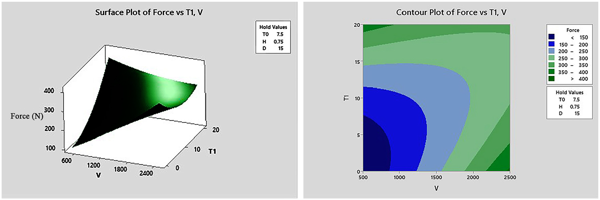
Response surface plot for variation of force by tool rotational speed (V) and dwell time (T1).
Figure 9 shows the interaction response of rotational speed V and tool diameter D for the initial holding time T0 = 7.5 s, dwell time T1 = 10 s, and penetration depth H = 0.75 mm. The results show that the joint strength increases by increasing the tool diameter D, but the joint strength will be reduced for a higher tool diameter (more than 20 mm). This is due to high heat generation in the tool’s frictional movement, material softening (and either decreasing the viscosity of PTFE), and easily extruding the softened material from the welding zone.
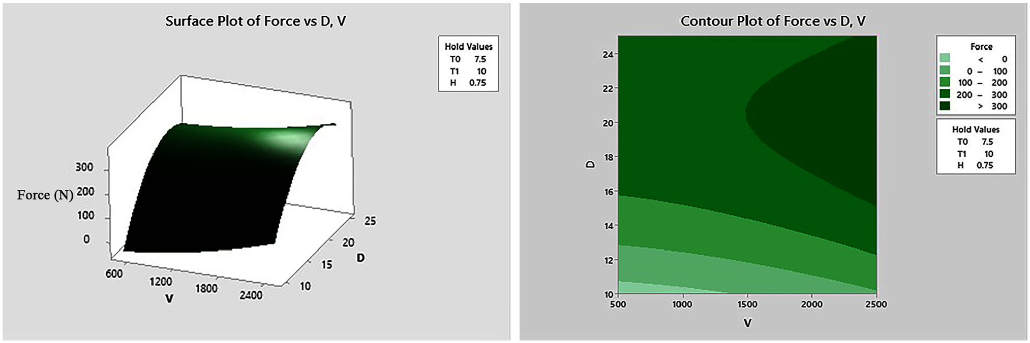
Response surface plot for variation of force by tool rotational speed (V) and tool diameter (D).
Figure 10 shows the response surface for rotational speed V and tool penetration depth H at specified conditions (T0 = 7.5 s, T1 = 10 s, and D = 15 mm). The results show that by increasing the penetration depth, the joint strength decreased first, and then it will be increased. The main reason for this observation relates to the mechanism of mechanical locking of polymer and metal parts in the threaded hole zone. The suitable filling of the threaded hole needs proper penetration depth and appropriate rotational speed.
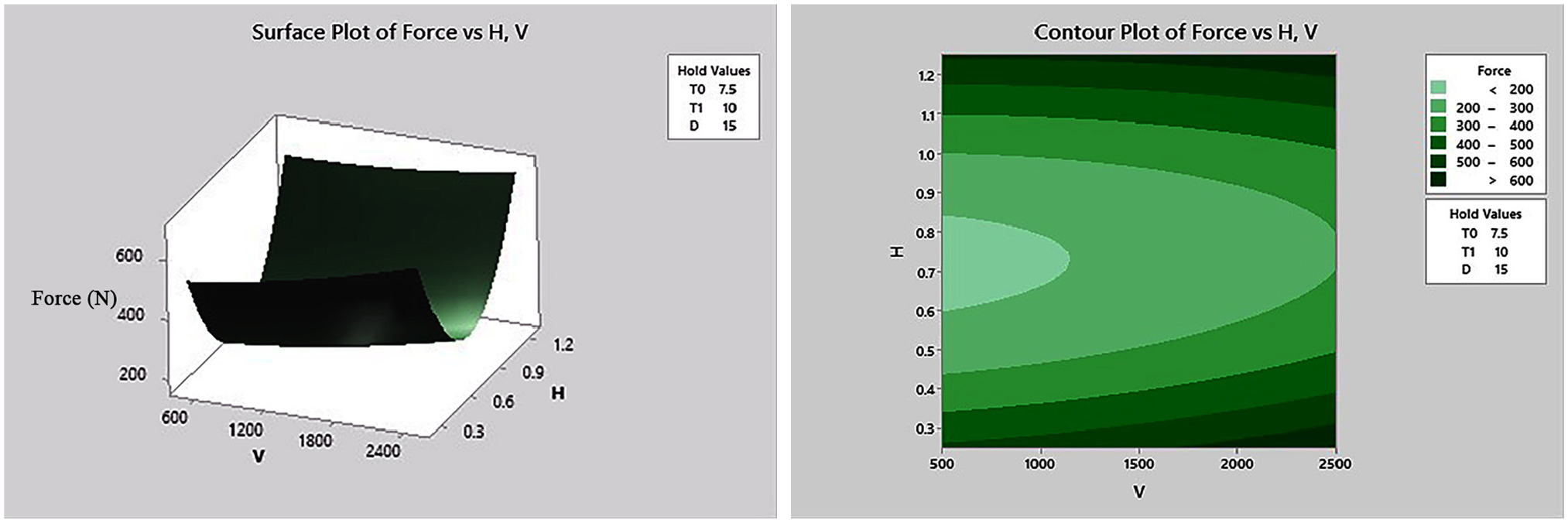
Response surface plot for variation of force by tool rotational speed (V) and penetration depth (H).
Figure 11 shows the response surface for tool diameter D and initial holding time T0 at specified conditions (V = 1500 rpm, T1 = 10 s, and H = 0.75 mm). The results show that the joint strength increased by increasing the tool diameter and initial holding time. The main reason for this observation relates to the frictional heat generated due to an increase in the contact surface and contact time.
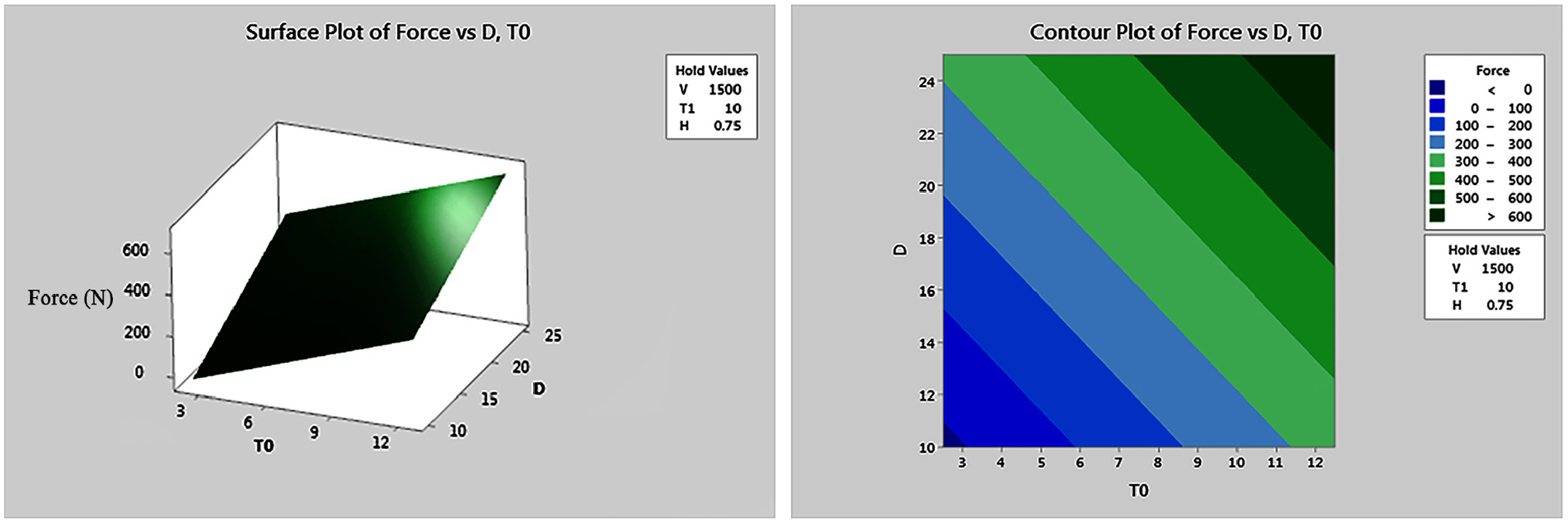
Response surface plot for variation of force by tool diameter (D) and initial holding time (T0).
Figure 12 shows the interaction plot for all process parameters. The detailed discussion mentioned above for individual process parameters and interaction of process parameters can be assessed in each part of the plot.
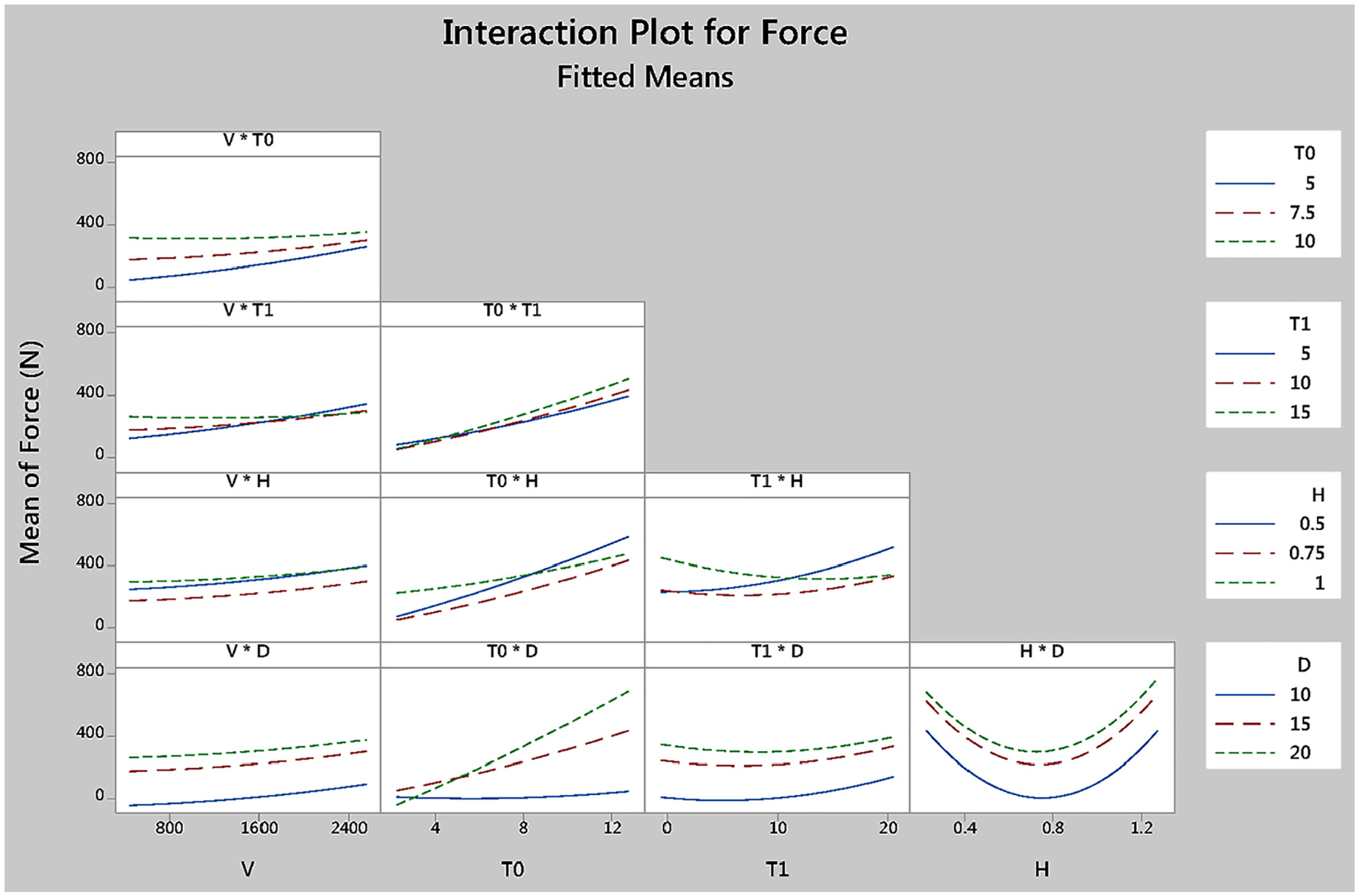
Response surface plot for variation of force by the interaction of all process parameters.
Conclusion
In this article, the joining of Polytetrafluoroethylene (PTFE, Teflon) and AA1050 aluminum alloy sheets are investigated experimentally. The joint strength was measured, and the effect of process parameters was analyzed using response surface methodology. The main finding of this study can be emphasized as follows:
- The friction stir spot welding (FSSW) process can weld metal to polymer successfully. The threaded hole helps to form a mechanical locking and increases the joint strength.
- The joint strength increases by increasing the tool rotational speed, initial holding time, and tool diameter. Increasing the generated heat due to the tool’s frictional movement improves the joining quality and wettability of PTFE and aluminum sheets. But higher heat generation leads to extruding the softened PTFE and decreases the joint quality.
- Increasing the penetration depth decrease the joint strength at first, and after a specified limit, the joint strength will increase by increasing the penetration depth.
- The response surface plot of process parameters shows that the effect of process parameters is not independent, and the joint strength depends on the combination of input parameters. The derived equation can predict the joint strength.
Footnotes
Declaration of conflicting interests
The author(s) declared no potential conflicts of interest with respect to the research, authorship, and/or publication of this article.
Funding
The author(s) received no financial support for the research, authorship, and/or publication of this article.