
Abstract
A fixture is a crucial component in the car dashboard manufacturing system and is used to position and restrain the car dashboard under external forces. However, the conventional fixture is only suitable for a specific type of car dashboard, which has poor adaptability. To this end, a new flexible fixture based on the N-X locating principle is proposed in this paper to adapt to different types of car dashboards. In the presented fixture, N clamping elements clamp the dashboard edge, while X movable supporting elements support the area close to the tool along the machining path. Furthermore, the fixture layout is optimized by combining a genetic algorithm (GA) and finite element analysis (FEA). In the optimization program, a multi-objective optimization function is established to suppress the deformation of the car dashboard. FEA is applied to calculate the machining deformation. The optimal locations of the fixture elements are determined by GA. A case is implemented to validate the proposed method and the results show that the maximum deformation and average deformation are reduced by 53.8% and 40%, respectively, compared with the empirical method.
Keywords
Introduction
A Fixture is considered to be a most important device in the car dashboard manufacturing system due to its excellent deformation suppression. However, the conventional fixture (see Figure 1) only adapts to a specific type of car dashboard, and has high manufacturing cost and design cycle. This has little impact on large-scale production, but has a significant impact on small-scale production. To solve this problem, the fixture should be flexible enough to accommodate different types of car dashboards. In addition, a reasonable fixture layout can effectively improve the machining quality of a car dashboard.
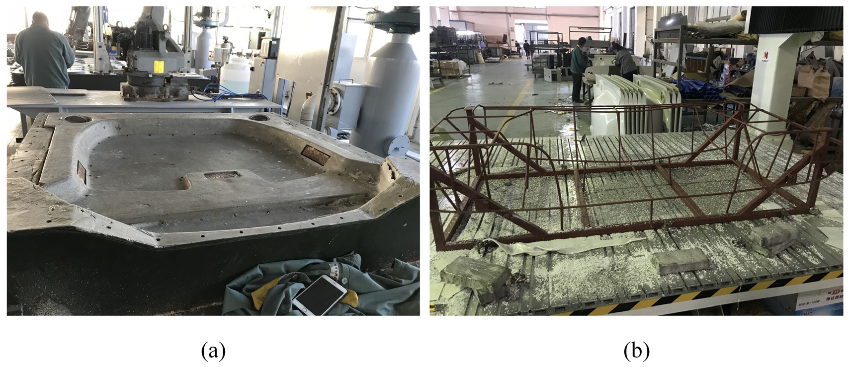
Conventional fixture: (a) mold support locating fixture and (b) steel frame fixture.
Over the decades, many fruits have been achieved in fixture layout optimization. These achievements mainly focus on rigid parts1,2 and sheet metal parts.3–5 While few studies are reported in the fixture layout optimization of non-metallic thin-walled parts.
Fixture layout optimization includes the selection of the locating principle and determination of the optimization method. The selection of the locating principle is the first step in fixture layout optimization. The traditional six-point locating principle is to set three, two, and one positioning points on the primary datum, secondary datum, and tertiary datum respectively to limit the six degrees of freedom of the workpiece. 6 Although this locating principle can satisfy the positioning requirements of the workpiece, it is only applicable to rigid parts and is not valid for flexible thin-walled parts.7,8 The main problem for flexible thin-walled parts manufacturing is the deformation in the normal direction caused by the machining load and the workpiece weight. Therefore, an efficient fixture design is to use multiple locating elements on the primary datum to form a positioning lattice consistent with the contour of the positioning surface. Based on this theory, N-2-1, 9 N-2-1-1, 10 N-3-2-1, 11 and N-M 12 locating principles have been proposed successively. These methods can meet the positioning requirements of different thin-walled parts, but they are deficient in some aspects. Firstly, excessive supporting elements can increase the system complexity. Secondly, the supporting elements are incapable to be arranged densely due to the practical structure, which leads to insufficient stiffness of the thin-walled parts in the processing position. Therefore, a new locating principle is demanded to solve these problems.
The determination of the optimization method is another issue that should be addressed. Typically, the optimization method depends on the experience of the designer to a large extent. As a result, for a given machining path, machining deformation is difficult to be controlled due to differences in individuals’ experience. To control machining deformation accurately, some optimization methods have been developed. These methods are mainly classified into two categories: numerical programming method and heuristic method. All the numerical programming methods13–16 start with an initial feasible layout and then optimize the scheme until the scheme cannot be further improved. The solutions obtained by these methods are very susceptible to the initial layout and usually cannot obtain the global optimal solution. 17 As an alternative method, heuristic methods, such as the genetic algorithm (GA),18–20 ant colony algorithm (ACA),21–23 and artificial neural network (ANN),24–26 are applied to fixture layout optimization. Based on the 3-2-1 locating principle, Selvakumar et al. 27 carried out fixture layout optimization by coupling GA and ANN to reduce workpiece deformation and machining forces. Wu et al. 28 developed a computer-aided fixture system for engine blades and presented an optimization algorithm combining GA and FEA to determine the optimal positioning points of the fixture. Yang et al. 29 constructed an optimization model for the positioning layout of sheet metal parts based on the N-2-1 locating principle and used the cuckoo search algorithm and FEA to obtain the optimal positions of N locators to minimize the deformation of sheet metal parts during machining. Khodabandeh et al. 30 used a combined multi-objective ACA and FEA method to obtain the optimal positions and numbers of fixture elements to improve the machining accuracy of the auto-body. Lu and Zhao, 31 extending the work of Cai et al., 9 proposed a fixture layout optimization method based on the 4-2-1 locating principle. Founded on FEA, GA and ANN were adopted to hunt for the optimum layout of the four fixture elements with the purpose to reduce workpiece deformation. The mentioned studies mainly focused on minimizing the average deformation of the workpiece. However, the large deformation caused by the local mutation of the workpiece should not be ignored for fixture layout optimization.
To solve the above problems, a new N-X locating principle is proposed, and a flexible fixture for various types of car dashboards is designed. Fixture layout optimization is carried out by combining GA and FEA. Finally, the proposed method is validated with a case study. The detailed process is described in the following sections.
N-X locating principle and problems
N-X locating principle
The car dashboard (see Figure 2), as a kind of typical difficult-to-machine thin-walled part, has the following characteristics. (1) It easily deforms during machining because of its low stiffness. (2) The surface roughness is large, and it is difficult to adopt a clamping device with a suction cup to fix. (3) Due to its complex structure, there is no clear primary datum. (4) Most of them have a cavity structure, and the edges can only be fixed by clamping. These characteristics of the car dashboard make the traditional 3-2-1 locating principle difficult to meet its positioning requirements. To ensure the stability and accuracy of the machining, more positioning and clamping points are required. To this end, this study presents a new N-X locating principle.
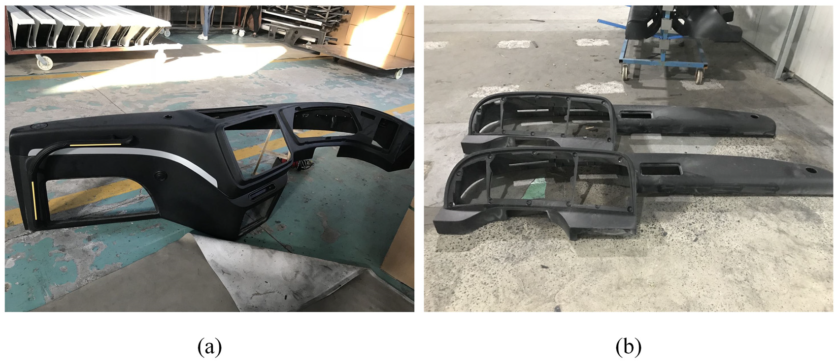
Different types of car dashboards: (a) type A car dashboard and (b) type B car dashboard.
The N-X locating principle is shown in Figure 3, where N clamping elements are used to clamp the edges of the workpiece, and X (X ≤ 3) movable supporting elements are periodically repositioned along the machining path to support the area close to the tool. The N-X locating principle is valid. When X = 1, the fixture system is similar to a mirror machining system. 32 When X = 2, the fixture system is similar to a self-reconfigurable fixture system. 33
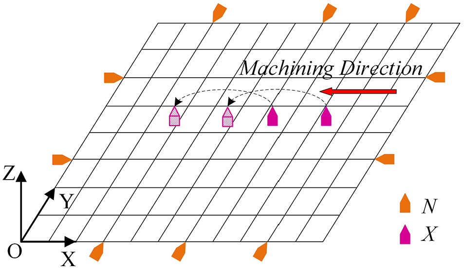
N-X locating principle.
A new flexible fixture for car dashboards is designed based on the N-X locating principle, as shown in Figure 4. The flexible fixture mainly includes the supporting element, clamping element, and base frame. Considering superfluous supporting elements will increase the control difficulty of the system, number X of the supporting element is considered to equal 2. Number N of the clamping element can be selected based on the structural characteristics of the car dashboard. The base frame adopts a sliceable structure, which can be assembled based on the actual size of the car dashboard.
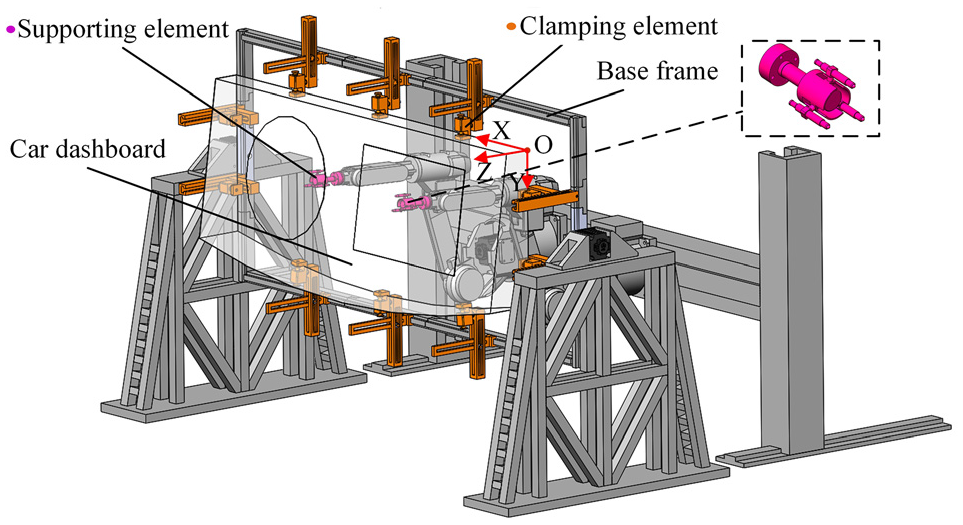
Flexible fixture based on the N-X locating principle.
Problems
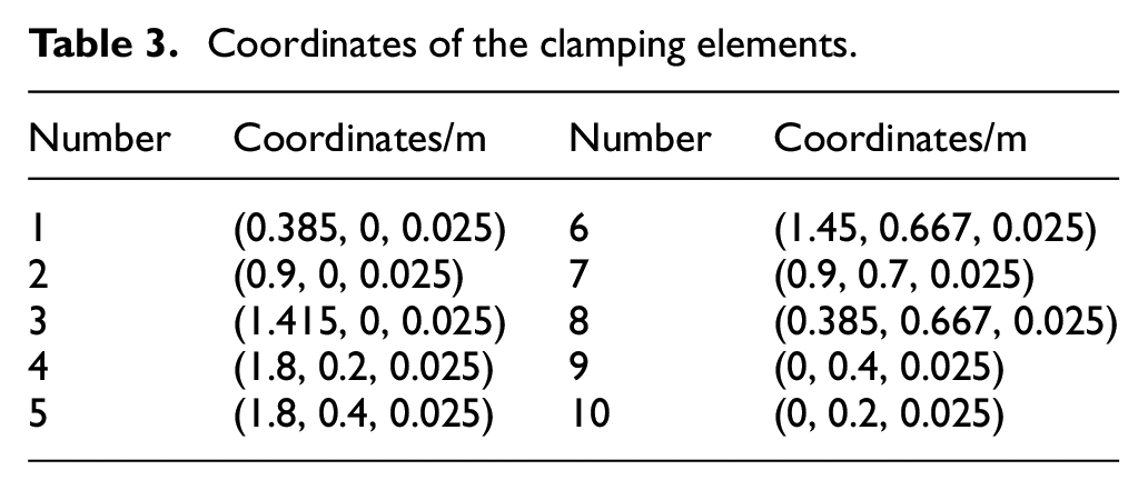
The difficulty of fixture layout optimization is determining the position of the clamping and supporting elements in the fixture such that the car dashboard can obtain the optimum machining quality. The position of the clamping element plays a minor role in improving the machining quality. Therefore, to reduce the running time of the computer, the uniform distribution method is adopted to layout the clamping element. Unlike the clamping element, the position of the supporting element directly affects the machining quality. Therefore, this study focuses only on the layout optimization of the supporting element. To facilitate the optimization process, the layout of the supporting element can be considered as the solution to the following three problems:
For a given machining path, how many positions does each supporting element need to support?
What is the coordinate of each support position?
When does the supporting element move from the current support position to the next support position?
Fixture layout optimization
Mathematical model
Objective
The layout scheme of the supporting element is considered as the solution to the three problems described in the last section, which is mathematically expressed as:
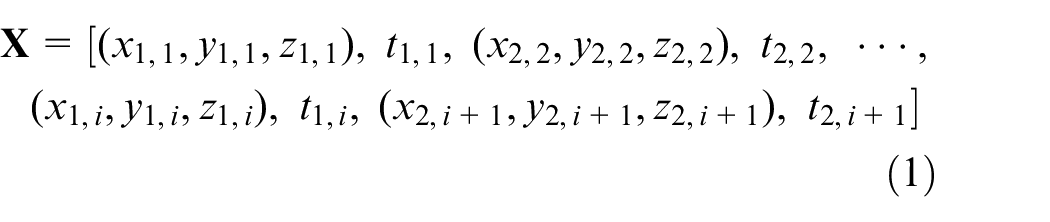
where subscripts 1 and 2 are the numbers of the two supporting elements. Subscript i represents the i-th support position. (x1,i, y1,i, z1,i) and (x2,i+1, y2,i+1, z2,i+1) represent the coordinates of the i-th support position and the i+1-th support position, respectively (the coordinate system is shown in Figure 3). t1,i represents the time when the first supporting element leaves current position i, and t2,i+1 represents the time when the second supporting element leaves current position i+1.
Layout optimization needs to not only maximize the uniformity of deformation but also avoid the large deformation caused by the local mutation of the car dashboard. Therefore, within the range of linear elastic deformation, a set of nonlinear equations is established as the objective function for layout optimization, as follows:
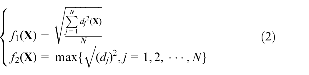
where N represents the number of mesh nodes in the finite element model of the car dashboard. dj is the normal deformation of the j-th node, and f1(
The layout optimization of the supporting element is a multi-objective optimization problem. To solve this problem, a linear weighting method is adopted. Then, the final objective optimization function can be represented as:

where λ1 + λ2 = 1, λ1 and λ2 are weight factors.
Constraints
The two supporting elements move alternately along the machining path during machining. Thus, the motion constraint equations of the two supporting elements can be expressed as:
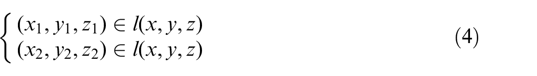
where (x1, y1, z1) and (x2, y2, z2) indicate the coordinates of the two supporting elements respectively, and l(x, y, z) represents the machining path equation.
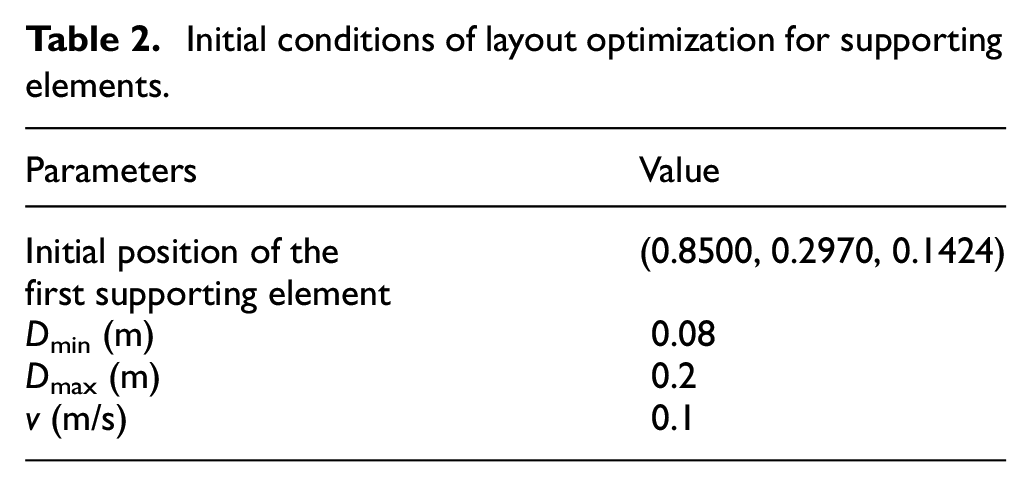
Due to the influence of the practical structure of the supporting elements, the distance between the two support positions must keep a minimum value to prevent interference. Moreover, the situation in which the distance is too large should be avoided, considering the stability requirements of the supporting element in the actual machining process. If the distance is too large, the supporting element will increase the moving speed to reduce the moving time, thereby affecting the stability of the supporting element indirectly. Therefore, the distance constraint between the two support positions can be expressed as:

where Dmin and Dmax are the minimum and maximum distances between the two support positions, respectively.
Finite element analysis
Analytic solution of the machining deformation of a car dashboard is hard to be obtained, due to the complicated structure. FEA, as an alternative numerical method, can solve the deformation problem of complicated structures efficiently. 34
The establishment of a finite element model is a complicated modeling process. The selection of the element type, mesh division, boundary conditions, and the application of an external load directly affect the machining quality of the workpiece.
The car dashboard is a complex thin-walled structure that is usually made by applying the polyurethane foaming process. In the finite element model, the element type is Shell181, mesh division is FREE, Poisson’s ratio is 0.38, elastic modulus is 1.3 GPa, and density is 500 kg/m3.
The boundary conditions are determined according to actual clamping conditions. As shown in Figure 3, the clamping elements are used to fix the edges of the car dashboard and the supporting elements are used to support the area near the milling point on the car dashboard. Therefore, in the finite element model, the part of the car dashboard clamped by the clamping element is fully constrained, and the part of the car dashboard supported by the supporting element is constrained in the normal direction of the contact surface.
An external load is applied by the tool. Because milling is an intermittent cutting process, the milling force changes periodically with time. To reduce the complexity of the simulation, the maximum value of the milling force is used to replace the variable external load.
In the modeling of milling forces, the tool is usually divided into finite element slices along the axial direction. The milling process of each element slice can be equivalent to an oblique cutting process as shown in Figure 5. Without considering the tool wear, the milling force acting on the j-th cutting edge in the i-th element slice can be decomposed into a tangential force, dFtj,i, a radial force, dFrj,i, and an axial force, dFaj,i. The total force on the tool is the sum of the forces on all element slices. Then, the milling forces on the tool in the X, Y, and Z directions can be obtained through a coordinate transformation. 35
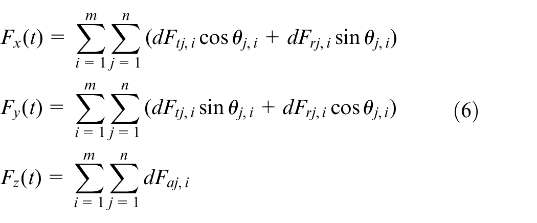
where θj,i is the angle of the cutting point of the j-th cutting edge in the i-th element slice. m is the number of element slices, and n is the number of tool flutes.
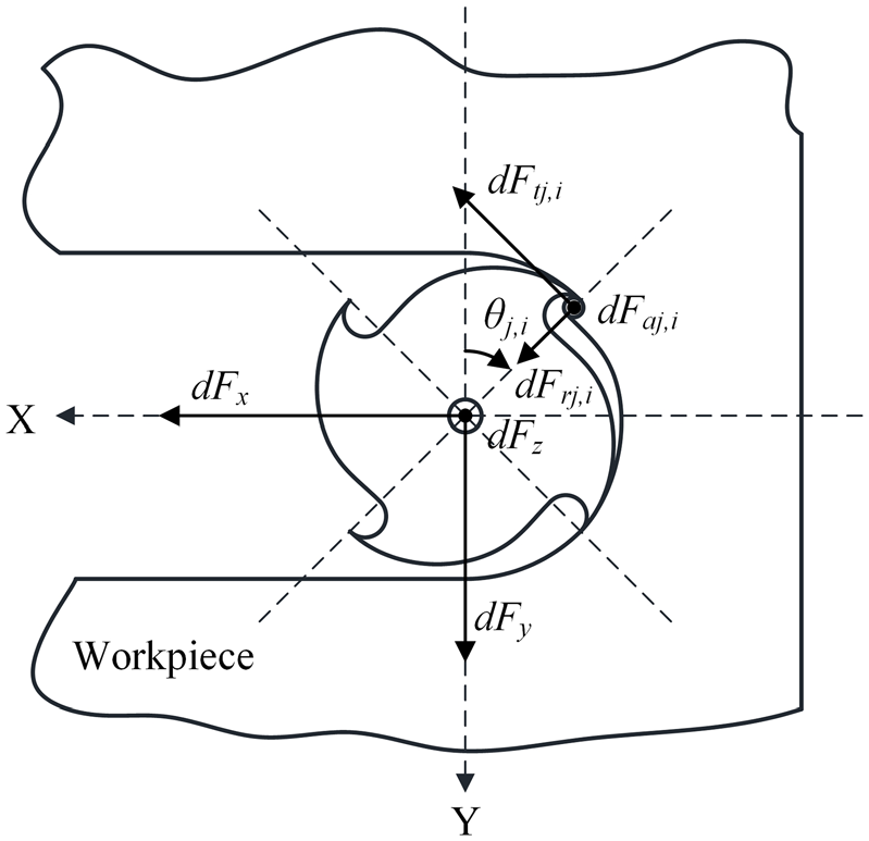
Milling force model.
Genetic algorithm
GA, first proposed by Professor Holland in 1975, 36 is a method to search for the optimal solution by simulating the natural evolution process. Its main feature is that it can directly operate on a structural object, robust, and globally optimizable. In addition, GA has the function of automatically searching the space and direction without additional constraints. 37 These properties of GA make it widely used in fixture layout optimization.38,39
The detailed process of GA is as follows:
Encoding
The commonly used encoding methods are binary encoding, floating-point encoding, and symbol encoding. To facilitate the implementation of crossover, mutation, and other genetic operations, binary encoding is used in this study. Encoding can represent the layout problems as strings or individuals in a genetic space. Each string represents a layout scheme, X. Based on a comparison between different strings, the best string considered by GA is mapped to the optimal layout scheme.
Initialization population
The individual is composed of a randomly generated binary-encoded string. A certain number of individuals forms a population. A population that is too small does not provide enough sampling points, and a population that is too large increases the computational effort. The population number should be between 20 and 160.
Fitness calculation
Fitness is an index used to measure the quality of an individual. The greater the individual fitness, the stronger is the ability to reproduce an offspring. The fitness in this study is evaluated according to the objective optimization function, F(X).
Selection
The selection operation is the selection of individuals with greater fitness from parents to inherit to the next generation. The commonly used selection operators are roulette wheel selection, sorting selection, stochastic tournament selection, and expected value selection. Roulette wheel selection is selected owing to its superior principle and simple operation.
Crossover
The crossover operation is the partial exchange of genes from two parents to generate two new individuals. Similar to the selection operation, there are many crossover operators, such as a single-point crossover operator, two-point crossover operator, multipoint crossover operator, and uniform crossover operator. The multipoint crossover operator is used because it promotes the search for the solution space rather than premature convergence. 10 The multipoint crossover operation is shown in Figure 6, two-parent strings are cut off at multiple random locations, and genes to the right of the cut-off point are exchanged to generate two new individuals. In this study, the crossover probability, Pc, is set to 0.6.
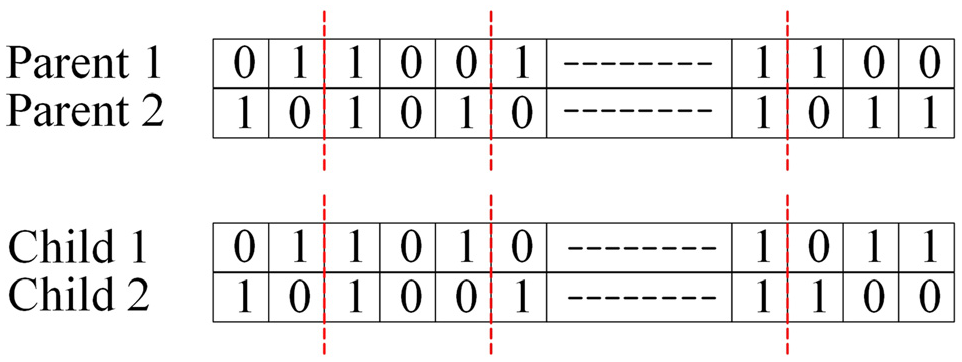
Multipoint crossover operation.
Mutation
The mutation operation indicates that some genes in an string change with a smaller mutation probability, Pm. As shown in Figure 7, a mutation of 1 to 0 occurs at the fifth byte of the string. Mutation increases the diversity of the population to prevent premature convergence. 33 To ensure the stability of population development, Pm should not be large. If Pm is too large, GA degenerates to a random search. In this study, Pm is set to 0.1.
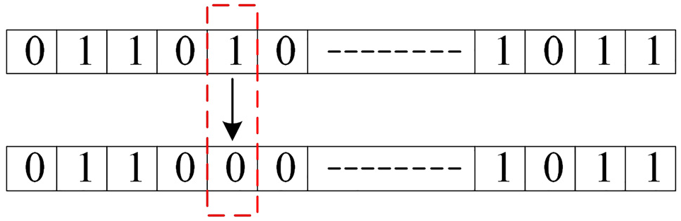
Mutation operation.
Optimization program
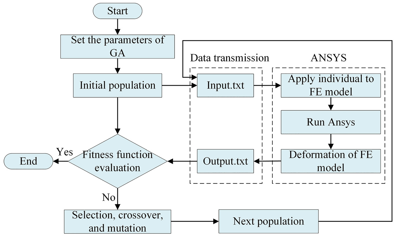
Fixture layout optimization is a multivariable optimization problem that aims to decrease the machining deformation of the car dashboard. The optimization method proposed in this study is a combination of GA and FEA, as shown in Figure 8. Firstly, GA stores the individuals (the positions of the supporting elements) generated in each generation in the Input.txt file. Secondly, ANSYS reads the Input.txt file and uses the values as design parameters of FEA. When FEA is completed, the deformation of the model is extracted and saved to the Output.txt file. Finally, MATLAB reads the Output.txt file and calculates the fitness of the values until the convergence condition is met. All the codes of GA are implemented in MATLAB, and the finite element parameter modeling is realized by using the ANSYS Parametric Design Language. The specific process of the fixture layout optimization program is as follows.
Step 1: Set the parameters of GA (population number, crossover rate, and mutation rate).
Step 2: Initialize the population: generate populations and individuals randomly.
Step 3: Save the individuals (the positions of the supporting elements) in the Input.txt file.
Step 4: ANSYS reads the Input.txt file and takes the values as the design parameters.
Step 5: Run ANSYS to calculate the machining deformation of the finite element model.
Step 6: Extract the relevant deformations and save them to the Output.txt file.
Step 7: MATLAB reads the Output.txt file and calculates the fitness.
Step 8: Determine whether the fitness function meets the convergence condition.
Step 9: If it does, switch to step 12 directly.
Step 10: Continue running the program of GA (selection, crossover, and mutation).
Step 11: Generate a new generation and return to step 3.
Step 12: Return the final result and stop the calculation.
Optimization program for supporting elements.
Case study and results
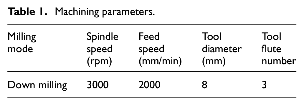
To validate the optimization method, a representative car dashboard model with the dimension of 1800 mm × 600 mm × 200 mm and thickness of 4 mm is studied in this section, as shown in Figure 9. There are two holes needed to be machined on the surface and the machining parameters are listed in Table 1. According to these parameters, the maximum values of milling forces applied to the machining path can be obtained as
Machining parameters.
Initial conditions of layout optimization for supporting elements.
Coordinates of the clamping elements.

Geometry of car dashboard.
Figure 10 shows the convergence results of the optimization algorithm, where the objective function reaches stability after nearly 100 iterations. The equivalent strain cloud diagram of the car dashboard after optimization is shown in Figure 11, and the maximum deformation is 1.2 mm. The average deformation is obtained to be 0.03 mm, which meets the requirements of machining quality, by extracting the deformation of each node in the model.
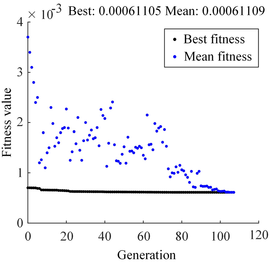
Convergence results of the optimization algorithm.

Deformation of the car dashboard under the optimal fixture layout.
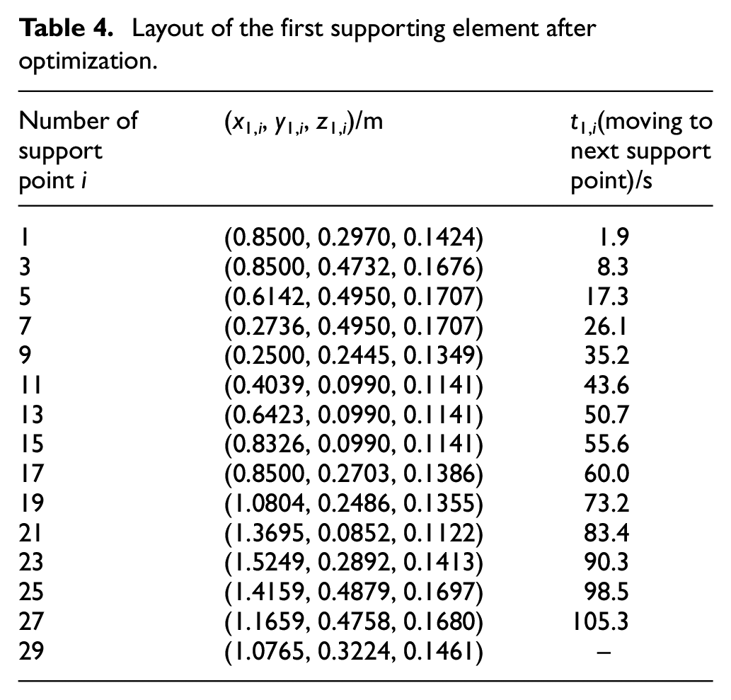
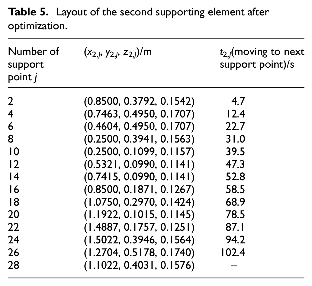
The optimal layout schemes of the two supporting elements are listed in Tables 4 and 5, and the numbers of support positions are 15 and 14, respectively. The layout results are shown in Figure 12. Figure 12(a) presents the distribution of the discrete support positions of the two supporting elements along the machining path. It can be observed that the closer the machining path is to the middle of the dashboard, the more intensive the support positions are. This is mainly attributes to the rigidity of the middle of the car dashboard is less than that of the outside. Figure 12(b) demonstrates the time distribution of the two supporting elements leaving their respective support positions, and the rectangular box represents the time required for the supporting element to move from the current support position to the next support position. The length of this time depends mainly on the distance between the two support positions.
Layout of the first supporting element after optimization.
Layout of the second supporting element after optimization.
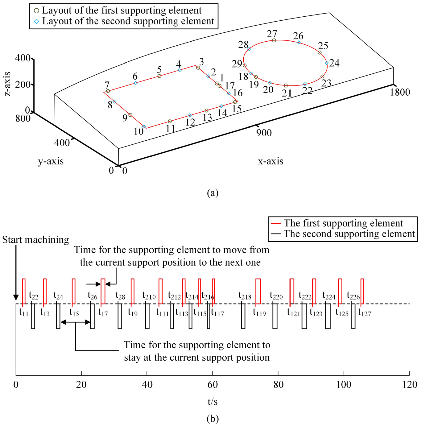
Layout of two supporting elements after optimization: (a) distribution of discrete support points of two supporting elements and (b) supporting elements moving time distribution.
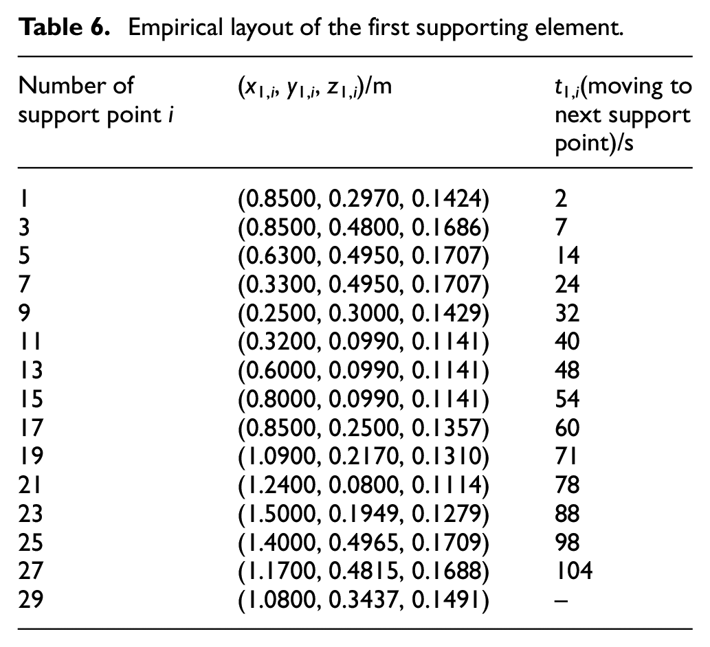
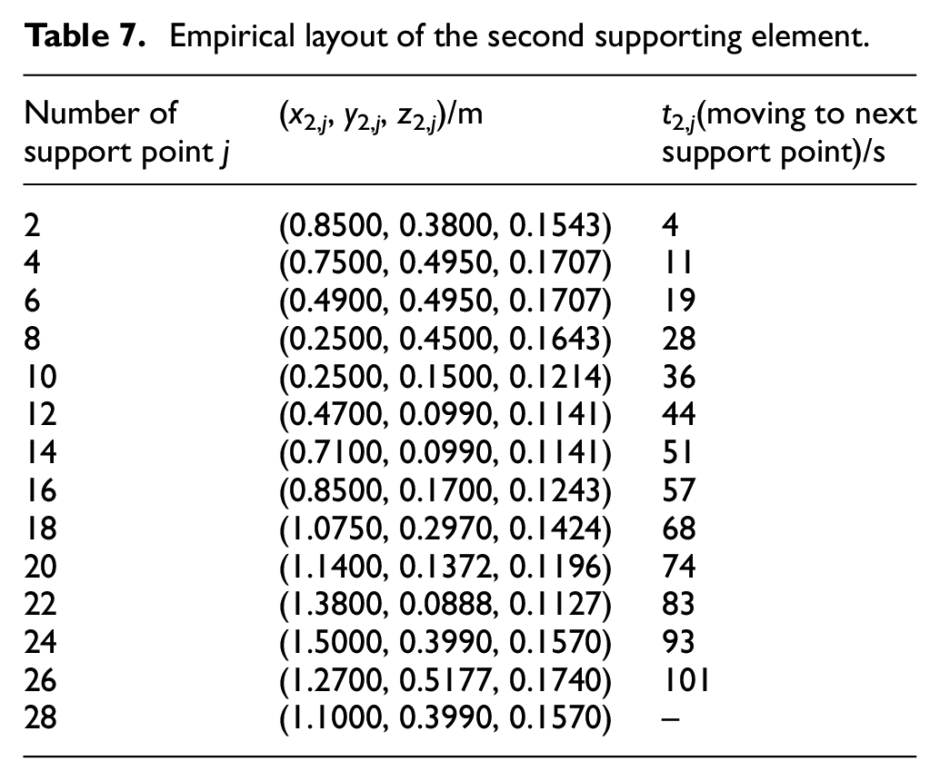
To further validate the superiority of the proposed method, an empirical method is also introduced in this section. The fixture layout schemes obtained by the empirical method are listed in Tables 6 and 7. Based on this layout schemes, the equivalent strain cloud diagram of the car dashboard can be obtained, as shown in Figure 13. The maximum deformation is 2.6 mm and the average deformation is 0.05 mm. What can be drawn from the comparison between the proposed method and the empirical method are that the maximum deformation and average deformation are reduced by 53.8% and 40%, respectively. Therefore, the proposed method is significantly better than the empirical method in terms of improving machining quality.
Empirical layout of the first supporting element.
Empirical layout of the second supporting element.
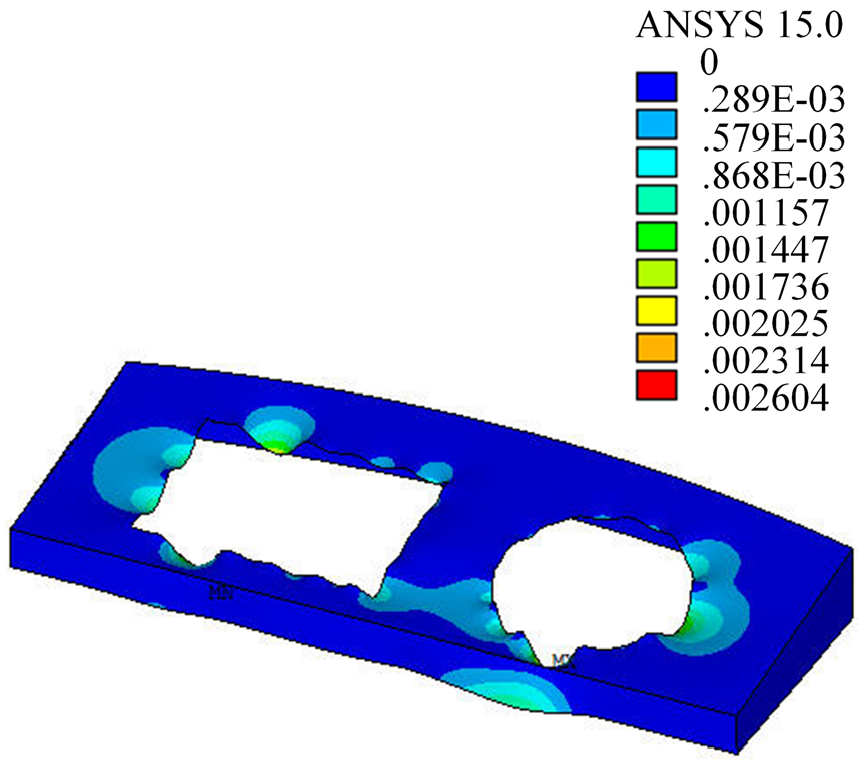
Deformation of the car dashboard under the empirical layout.
The flexible fixture is still in the preliminary design stage as some key technologies have not yet been resolved. In the future, this work will be further improved and perfected.
Conclusion
This paper proposes a new N-X locating principle to satisfy the positioning requirements of different types of car dashboards. Based on this principle, a fixture layout optimization algorithm for car dashboards is developed and realized. The major conclusions are as follows:
A fixture layout optimization algorithm is developed by combining GA and FEA to obtain the optimal positions of X supporting elements. In the optimization algorithm, a multi-objective optimization function is established to minimize the deformation of the car dashboard.
A new flexible fixture that can accommodate different types of dashboards is designed. The fixture has lower manufacturing cost and control difficulty due to its excellent adaptability and fewer supporting elements, which is of great significance to the development of small and medium-sized automobile enterprises.
The proposed method is verified with a case study and the results show that the maximum deformation and average deformation are reduced by 53.8% and 40%, respectively, compared with the empirical method.
Footnotes
Appendix
Declaration of conflicting interests
The author(s) declared no potential conflicts of interest with respect to the research, authorship, and/or publication of this article.
Funding
The author(s) disclosed receipt of the following financial support for the research, authorship, and/or publication of this article: This work was funded by National Science and Technology Major Project of China. The fund number is 2019ZX04029001.