
Abstract
This paper reports on reduction of noise and vibrations of cylindrical and conical gears through simultaneous reduction in their microgeometry errors, functional parameters, and surface roughness by finishing them with abrasive flow finishing (AFF) process. Previously identified optimum values of AFF medium viscosity and finishing time were used during AFF of the chosen gears. Noise and vibrations characteristics of the unfinished gears and the AFF finished gears were studied by varying motor speed and applied load at four levels each. An indigenously developed test rig was used for spur and straight bevel gears whereas drivetrain diagnostic simulator was used for helical gears. Indigenously developed dual flank roll tester was used to evaluate functional parameters of the unfinished and the best finished gears by AFF process. It was found that AFF process simultaneously reduced microgeometry errors, functional parameters, maximum and average values of surface roughness of spur, helical, and straight bevel gears. It reduced noise and vibration by 5.2 dBA and 5.3 m/s2 for spur gears, by 3.4 dBA and 7.5 m/s2 for helical gears, and by 4.6 dBA and 4 m/s2 for straight bevel gears. This study proves that AFF is an easy-to-operate and effective process for reducing noise and vibrations of cylindrical and conical gears through simultaneous reduction in their microgeometry errors, functional parameters, and surface roughness values. Outcome of this work will be helpful for various manufactures and users of different types of gears.
Keywords
Introduction
A gear is a modified form of a wheel having uniformly spaced teeth placed on its circumference. A gear pair is used for transmission of motion and/or power, to change speed ratio, to change direction of rotation of their mounting shafts (i.e. conical gears). Billions of gears are manufactured and consumed annually for various applications in automobiles, avionics, marine engines, industrial machineries, wind turbines, power plants, micro and nanodevices, agriculture and farm machineries, material handling equipment, construction machineries, office automation, etc. Figure 1 presents the desired design characteristics, and the requirements for better performance and enhanced service life of a gear which should be met by a gear manufacturer. 1 Increase in speed and load, microgeometry errors (i.e. errors in profile, lead, pitch, and runout), functional testing parameters (i.e. total composite error, tooth-to-tooth composite error, transmission error, radial runout, total pitch error), and higher values of flank surface roughness of a gear lead to its incorrect and uneven meshing with its mating gear resulting in increased gear noise and vibrations. These parameters contribute approximately 30% in generation of gear noise and vibrations. 2 There are three types of gear noise: (a) whining noise caused by the vibrations generated during meshing of gears. Errors in gear microgeometry are its primary cause, (b) rattle noise caused by repeated impacts on teeth of a driven gear which result due to torsional vibrations of its driving gear, and (c) hammering noise occurring due to sudden increase in dynamic load on a gear caused by an increase in the nominal torque. Continuous increase in gear noise and vibrations can eventually cause premature failure of a gear.
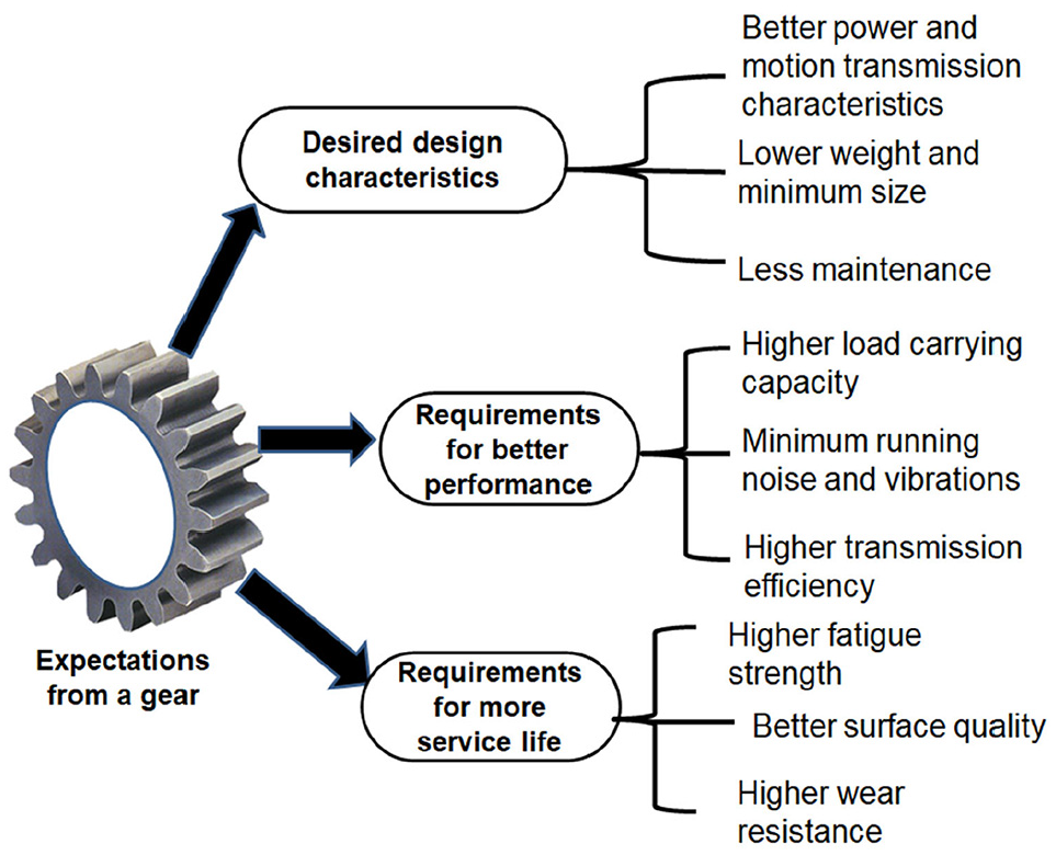
Desired characteristics from a gear.
Considerable reduction in noise and vibrations of a gear can be achieved by its finishing by an appropriate process which will (i) reduce microgeometry errors, functional testing parameters, surface roughness, and remove sharp burrs and corners, (ii) impart flank modifications such as end relief, tip relief, root relief, profile crowning, flank crowning, and (iii) improve its contact ratio. 3 It implies that gear finishing plays a very crucial role in improving quality of a gear and it contributes nearly 60%–70% to the overall production cost of a gear. 4
Deutsches Institut fur Normung (DIN) standard 3962 and DIN standard 3965 are the most frequently used standards for expressing quality of cylindrical gears and conical gears respectively. It has 12 categories ranging from 1 to 12 with DIN 12 indicating worst quality gear and DIN 1 indicating the best quality gear. 5 Grinding, honing, shaving, burnishing, and lapping are conventional finishing processes for gears. However, these processes suffer from some intrinsic drawbacks and associated undesirable effects as mentioned in the following paragraphs. Gear grinding can finish case-hardened spur, helical, and bevel gears in smaller duration. It can yield average surface roughness as 0.3–0.8 µm and DIN 6-7 gear quality normally and up to DIN 3 with extreme care. However, it generates transverse grind lines and grind burns on flank surfaces of a ground gear which damages its surface morphology and increases its running noise. Indexing error in teeth of a grinding wheel can also increase noise of a ground gear. Moreover, it is very costly process due to the required equipment and operator skills. Gear shaving is an economical and faster process for minor reduction of errors in profile and lead of spur, helical, and worm gears having hardness up to 40 HRC. It can achieve 0.4–0.6 µm as average surface roughness and gear quality of DIN 7 and up to DIN 3 with special care. However, this process removes more material from the pitch surface of a gear, which adversely affects its transmission efficiency. Also, cost and wear of shaving cutter are also higher. Gear lapping can correct minute errors in profile, lead angle, tooth spacing, and eccentricity of the hardened gears by finishing them in non-interchangeable pairs. It can achieve gear quality of DIN 6-7 and 0.08–0.25 µm value of average surface roughness. Gear honing can correct microgeometry errors, dimensional inaccuracy, surface roughness, lay pattern of case-hardened internal and external gears producing crosshatch lay pattern which is helpful in lubricant retention thereby lowering friction and improving wear characteristics of a honed gear. It gives gear quality of DIN 6-7 and average surface roughness value of 0.13–1.25 µm. Gear burnishing is used to reduce minor errors and improve fatigue strength of unhardened internal and external helical gears only and can achieve gear quality up to DIN 7. It generates localized surface stresses and non-uniform surface characteristics. Also, burnishing dies are very costly. 4
Research work has been done on reducing noise and vibrations of different types of gears by decreasing their surface roughness by conventional gear finishing processes. Masuda et al. 6 proposed a semi-empirical equation consisting of a dynamic term representing noise level of a gear. It can be used to compute noise levels of the gears finished by different conventional finishing processes by considering errors in the finished gears in their noise and vibration analysis. They used this equation to predict noise of spur and helical gears finished by gear grinding and reported that (i) noise reduced by 9.5 and 13.5 dB for Niles-type and Maag-type grinding processes respectively for both spur and helical gears, and (ii) vibrations was less in Maag-type grinding than Niles-type grinding for both spur and helical gears. Liu et al. 7 studied noise of the ground spur gears used in the headstock of a machine tool by conducting 242 experiments and reported that (i) gear finishing has a significant impact on reduction of gear noise and vibrations and that the finished gears give lesser noise than the unfinished gears, (ii) gears having smaller errors in microgeometry and functional testing parameters (i.e. pitch error, profile error, and transmission error) yield reduced noise level, (iii) maximum and minimum values of noise were 85 and 75.7 dB respectively, and (iv) noise reduced by 5–6 dB for internal honing process than gear grinding. Akerblom and Parssinen 8 used gear shaving and gear grinding to finish eleven gear pairs and concluded that (i) reduction of transmission error is an important excitation mechanism to reduce gear noise, (ii) improving surface finish reduces gear noise by1–2 dB approximately at lower torque level, (iii) increase in lead error increase gear noise level by 1–3 dB, (iv) shaved gears were less noisy than the ground gears, (v) gears ground with the threaded grinding wheel are less noisy than those gears ground by profile grinding wheel, (vi) increase in face width decreases noise and vibrations by approximately 5 dB, and (vii) increase in lead crowning decreases noise and vibrations levels by 1 and 3 dB respectively. Jolivet et al. 9 compared noise and vibrations of the gears finished by grinding and power honing process by studying gear teeth topography and vibrations using multiscale analysis based on continuous wavelet transform and reported that (i) surface roughness values produced by two processes are very close to each other, and (ii) ground gears produce lesser vibrations than the power honed gears with the difference being 0.2 dB at first harmonic and 0.3 dB at second and third harmonic. Bihr et al. 10 compared noise levels of two gearboxes whose gears had different values of errors in their microgeometry and concluded that the gearbox having smaller values of microgeometry errors generated lesser noise. Jolivet et al. 11 studied role of gear finishing process in reducing noise of helical gears under dry and wet lubrication conditions. They compared surface roughness of the unfinished helical gear with grinding finished worm meshing gears and honing finished internal meshing gears and reported that (i) gear finishing process has significant impact on reduction of noise and vibrations of a gear. Ground gears generate lesser vibrations than the honed gears, and (ii) dry lubricated gear finishing results in higher vibrations of a gear than the corresponding wet lubricated process. Jolivet et al. 12 studied effects of surface roughness on frictional noise (i.e. generated due to contact asperities) and found that an unfinished gear has higher frictional noise than the same gear finished by grinding and power honing. Tomeh 13 reported that grinding and superfinishing of gears significantly reduce noise and vibrations in a gearbox. Based on the review of the past work, it can be concluded that (i) very limited work has been reported on reduction of noise and vibrations of gears by finishing them properly, (ii) each conventional finishing process for gears has some major limitations and its applicability limited to particularly type of gears, and (iii) no work is available on reduction of functional parameters of a gear (namely tooth-to-tooth composite error, total composite error, and radial runout) by any gear finishing process.
It is evident from these conclusions that there is a requirement to develop an advanced finishing process for gears which can simultaneously reduce microgeometry errors, functional parameters, surface roughness parameters and consequently reduce gear noise and vibrations in minimum possible finishing time. Abrasive flow finishing (AFF) is an advanced nano-finishing process which has been used for deburring, radiusing, polishing complicated and intricate shapes and difficult-to-machine materials by flowing abrasive laden viscoelastic putty through or over the component. It can attain average surface roughness up to 50 nm; dimensional tolerance up to ±5 µm; and can finish products by removing material thickness in the range of 1–10 µm.14,15 It is frequently used to finish the components used in aerospace, automotive, medical implants, mold and dies, pump, and to remove recast layer from the products manufactured by wire electrical discharge machining (WEDM) process.16,17 Some researchers used AFF to finish different types of gears focusing on reduction of their surface roughness only. Xu et al. 18 used AFF for finishing helical gears and reported significant reduction in surface roughness of flank surfaces of gears with high processing efficiency. Venkatesh et al. 19 used AFF for finishing straight bevel gears made of EN-8 steel and found 50% reduction in surface roughness. Venkatesh et al. 20 hybridized AFF with ultrasonic vibrations to develop ultrasonic-assisted AFF (UA-AFF) to finish straight bevel gears made of EN-8 steel. They found that UA-AFF process gives more reduction in surface roughness than AFF process for same finishing time. Petare and Jain21,22 reported that AFF process can simultaneously reduce microgeometry errors and surface roughness along with improvement in microhardness and wear resistance of spur and straight bevel gears made of 20MnCr5 alloy steel. However, no work has been reported on reduction of noise and vibration and functional parameters of cylindrical and conical gears by AFF process. Therefore, present work aims to fulfill this gap by focusing on reduction of noise and vibrations and functional parameters of spur, helical, and straight bevel gears through their finishing by AFF process by comparing these parameters for the AFF finished gears with the corresponding unfinished gears. This will help to establish AFF as a flexible and economical finishing process for noise and vibrations reduction and improving functional parameters of different types of gears.
Materials and methods
Gear specifications
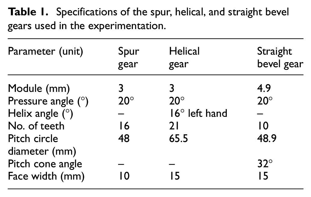
Gears used in the experiments were made of 20MnCr5 alloy steel. It is a case-hardened alloy steel having 1000–1300 N/mm2 as tensile strength and 50 Rockwell hardness at C-scale (HRC). It is used for commercial production of gears, shafts, camshafts, spindles, pistons, bolts, valve bodies, pumps, and fittings. Its chemical composition (by %wt.) is: 1.19% Mn; 1.1% Cr; 0.189% C; 0.019% P; 0.289 %; Si; 0.017% S and balance Fe. Table 1 presents specifications of spur, helical, and straight bevel gears used in the present work.
Specifications of the spur, helical, and straight bevel gears used in the experimentation.
Experimental apparatus and gear fixtures
A vertical configuration experimental apparatus for two-way AFF process was developed by Petare and Jain21,22 for finishing the gears. Its photograph is shown in Figure 2(a). It consists of a hydraulic power pack unit having capacity of 20 MPa extrusion pressure to power the two hydraulic cylinders which are connected to the vertical cylinders (containing the finishing medium) by means of threaded support bars. Limit switches and proximity sensors are mounted on a support bar in the space between hydraulic cylinder and the medium-containing cylinder. Limit switch controls piston stroke length of the hydraulic cylinder whereas the proximity sensor counts number of strokes of piston in a hydraulic cylinder that is, movement from top to bottom position or from bottom to top position is counted as one stroke and two such strokes constitute one cycle. A structure of steel plates and support bars has been used to support the entire assembly of hydraulic cylinders, medium-containing cylinders, limit switches and proximity sensors. Space between upper and lower cylinders is used to mount the fixture containing the workpiece. Prepared finishing medium is filled in one of medium-containing cylinders and their pistons extrude back and forth the finishing medium through the passage formed by the workpiece gear and its developed fixture. Three special fixtures were developed to hold and support spur gear, 21 helical, and straight bevel gear 22 to enable their finishing by AFF process and are depicted in Figure 2(b)–(d), respectively. Each fixture has two cylindrical discs made of metalon with both the discs having a concentric hub made on a cylindrical protrusion for mounting the workpiece gear. Fixtures for spur gear (Figure 2(b)) and helical gear (Figure 2(c)) have 16 and 21 circumferential holes of 5 mm diameter drilled in both lower and upper discs at a circumferential location determined by their respective pitch circle diameter. Fixture for straight bevel gear (Figure 2(d)) has 10 circumferential holes of 8 mm diameter in upper disc and 5 mm diameter holes in lower disc drilled as per outside and inside pitch circle diameters of straight bevel gear. These holes allow entry and exit of the finishing medium after finishing of flank surfaces of a workpiece gear. Four locating pins were provided to avoid any relative displacement between the lower disc and upper disc during finishing of a gear. A central hole was drilled in both the discs to lock them together. Workpiece gear is mounted in its respective fixture in such a way that it is held firmly against high extrusion pressure and guides the finishing medium between flanks of two consecutive teeth thus finishing them along their entire face width.
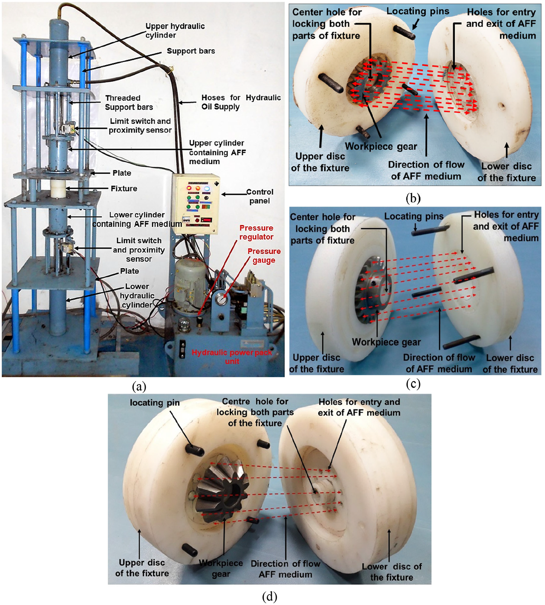
Photographs of (a) experimental apparatus for finishing cylindrical and conical gears by AFF process, and fixtures for(b) spur gear, (c) helical gear, and (d) straight bevel gear.
Details of experimentation
Finishing medium having 1156 cm 3 volume (determined by dimensions of the finishing medium-containing cylinder) comprising of 30% silicon carbide abrasive particle of mesh size 120 (i.e. avg. size as 127 μm diameter), 10% silicon oil and 60% putty was prepared by thorough hand mixing followed by pressing it in a deep drawing machine. Molding clay was selected as a putty material due to its excellent ability to hold the abrasive particles, low cost, and easy availability. Silicone oil was selected as the blending oil because it helps in easy control over the viscosity of the finishing medium. Rheometer (MCR-301 from Anton Paar, Germany) was used to measure viscosity of the prepared finishing medium which was found as 135 kPa s. Interaction of abrasive particles contained in the finishing medium with the workpiece gear teeth causes shearing off the surface peaks from their flank surfaces, reducing their microgeometry errors, surface roughness, and functional parameters. Extrusion pressure, finishing time, volumetric concentration of silicone oil, and volumetric concentration and size of the abrasive particles are significant parameters of the AFF process which affect microgeometry errors and surface roughness of AFF finished spur, helical, and straight bevel gears. Two identical spur gears and helical gears were manufactured on a gear hobbing machine whereas two identical straight bevel gears were manufactured on a conical gear shaper machine. Blanks for all these gears were manufactured on a lathe machine. Previously identified optimum values of finishing time (25 min for spur and helical gears and 30 min for straight bevel gear), extrusion pressure as 5 MPa were used.21,22 Microgeometry errors and surface roughness values of the finished gears were compared with the values of microgeometry errors and surface roughness of previously finished gears by Petare and Jain21,22 and Petare et al. 23 using same parametric combination and found close agreement in both the values. These gears have been referred as the best finished gears in the subsequent text. Functional parameters, microgeometry errors, and surface roughness values were measured for the unfinished and the best finished gears and percentage changes in these values were computed. Noise and vibrations of the unfinished and the best finished spur, helical, and straight bevel gears were measured by varying speed and the applied load at four levels each (i. e. conducting 16 experiments for each type of gear) as mentioned in Table 2 along with the fixed parameters. Change in noise level “ΔN” and vibration level “ΔV” were computed using the following equations
Details of parameters used in the measurement of noise and vibration of the gears.
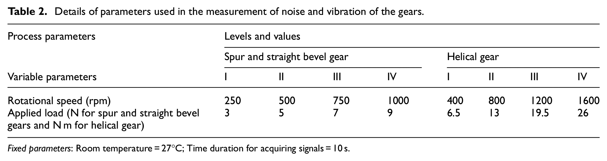
Fixed parameters: Room temperature = 27°C; Time duration for acquiring signals = 10 s.
Measurement of the responses
Measurement of noise and vibrations
An in-house developed experimental test rig (depicted in Figure 3(a)) was used to measure noise and vibration of the unfinished and the best finished spur and straight bevel gears. It has following two independent gearboxes each driven by a dedicated motor: (i) gearbox developed by Kumar et al. 24 for testing spur gear with its master gear mounted on parallel shaft (Figure 3(a1)), and (ii) gearbox developed by Kashyap et al. 25 for testing straight bevel gear with its master gear mounted on two perpendicular shafts (Figure 3(a2)). The test rig has a variable frequency drive (VFD) to control speed of the motor of a driver gear in any gearbox. Noise and vibrations of the unfinished and the best finished helical gears were measured using the drivetrain diagnostics simulator (DDS) whose photograph is depicted in Figure 3(b). The workpiece helical gear and its master gear were mounted on parallel shafts of the DDS gearbox as depicted in Figure 3(b1) and the motor of the gearbox was run at the desired speed. Desired value of the load was applied manually in case of driven spur or straight bevel gear. Torsional load (in the range from 2.03 to 43.38 Nm) was applied by programmable magnetic brake of the DDS for driven helical gear. Microphone (placed at 1 m distance from the concerned gearbox) and a tri-axial accelerometer (mounted over the concerned gearbox) were used to record signals of noise and vibrations respectively for the unfinished spur, helical, and straight bevel gears and the corresponding best finished gears. The aquired signals were transferred to four-channel noise and vibrations data acquisition system OR 35 (from OROS, France) and its associated software (NV Gate 9.0, 3-series) was used for analyzing them.
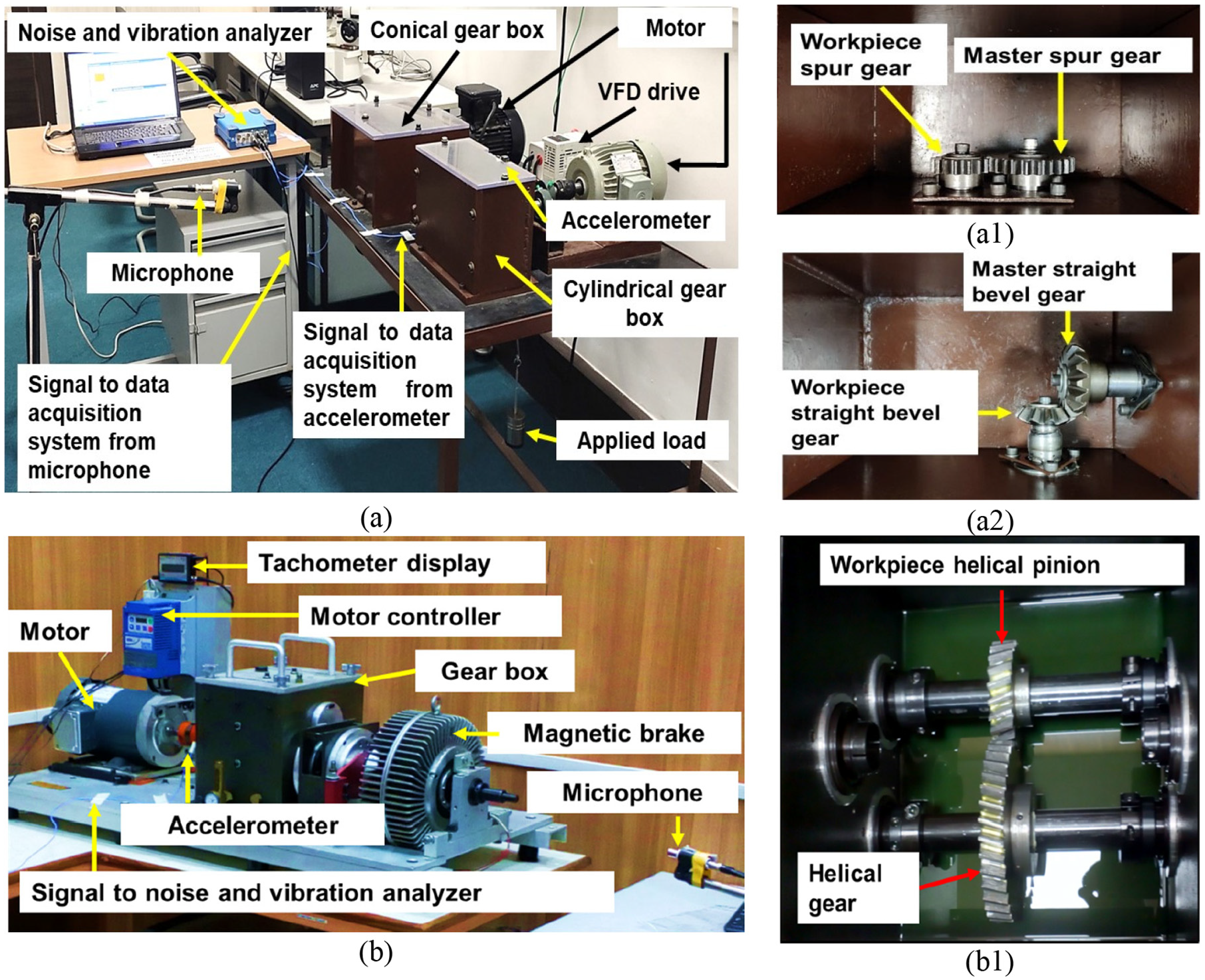
Photographs of equipment used for measurement of noise and vibrations of gears: (a) test rig for spur and straight bevel gears and arrangement of workpiece and its master gear for (a1) spur gear and (a2) straight bevel gear and (b) drivetrain diagnostics simulator (DDS) for helical gears and (b1) arrangement of workpiece gear and its master gear in it.
Evaluation of functional parameters of gears
Functional testing of a gear simulates its actual working conditions by meshing it with a master gear and recording variations in their center-to-center distance as they mesh together and rotate. Tooth-to-tooth composite error “fi,” total composite error “Fi,” and radial runout “Frf” are the functional parameters determined by the dual flank roll testing. Tooth-to-tooth composite error“fi” is a variation in the center-to-center distance per tooth per revolution (i.e. 360°/number of teeth). It includes the effects of errors in profile, pitch, tooth thickness, and tooth alignment in a workpiece gear. Total composite error“Fi” is the total change in the center-to-center distance in one complete revolution of the gear being inspected. It is the combination of runout with tooth-to-tooth composite error. Radial runout (determined from functional testing) “Frf” of a workpiece gear is the difference between the maximum and the minimum radial distance from the gear axis as observed by removing the short-term or undulation pitch deviations and analyzing the long-term sinusoidal waveform. 26 Functional parameters for the unfinished and the best finished spur and helical gears were measured on the dual flank roll tester developed in-house by Kasliwal et al. 27 whose photograph is depicted in Figure 4. It has provision to mount the workpiece gear and its master gear whose theoretical center distance can be adjusted by a lead screw. They are made to mesh with each other maintaining dual flank contact and are rotated by a stepper motor whose speed is controlled by an Arduino-based microcontroller. A laser displacement sensor records variation in center-to-center distance between the workpiece and the master gears by observing the movement of the plate on which the master gear is mounted. Computer numerically controlled (CNC) dual flank roll tester (DO-125 KPC from Gearspect, Pune, India) was used to measure the functional parameters for the unfinished and the best finished straight bevel gears. Speed of the rotation of workpiece gear is controlled by its associated software which also records the variations in the center-to-center distance between the workpiece and master gears and gives its variation in the form a plot and computed values of functional parameters of the workpiece bevel gear.
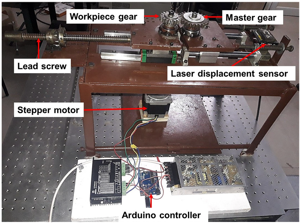
Photograph of dual flank roll tester used for functional testing of spur and helical gears.
Evaluation of surface roughness
Roughness of flank surfaces of a gear influence its contact with its mating gear and its load-carrying capacity. Therefore, values of maximum surface roughness “Rmax” and average surface roughness “Ra” on left hand (LH) and right hand (RH) flank surfaces of two randomly chosen teeth of a workpiece gear were measured at two equidistant locations from their end as shown schematically by red color lines in Figure 5 that is, total eight values of Rmax and eight values of Ra were measured for one gear. It involved tracing 10 µm diameter probe on 3D surface roughness measuring equipment MarSurf LD-130 (from Mahr Metrology, Germany) using 0.8 mm as cut-off length, 4 mm as evaluation length, and gaussian filter to distinguish between roughness and waviness parameters. Arithmetic mean of the eight measured values of Rmax (or Ra) was used for further analysis. Three-dimensional surface profiles of the tooth flank surfaces of an unfinished and the corresponding finished gears were also measured.
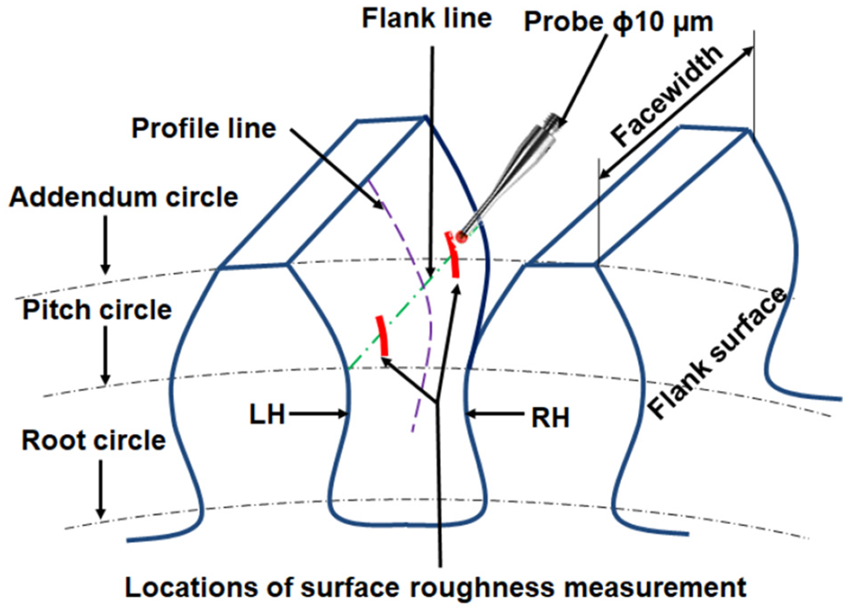
Details of measurement of flank surface roughness of a workpiece gear.
Evaluation of microgeometry errors
Gear microgeometry errors have two components: form error (i.e. errors in profile and lead) and location error (i.e. errors in pitch and runout). Total profile error“Fa” is a combination of deviations or errors in form and slope of the involute profile. It is evaluated perpendicular to the involute profile by tracing the probe from root to tip at middle of the face width. It significantly affects the noise generation characteristics of a gear. Total lead error“Fβ” is a combination of errors in the form and slope of the lead of the tooth flank. It is evaluated by tracing the probe along the pitch line along the face width of a gear. It affects load carrying capacity of a gear. Pitch and runout errors influence motion transfer characteristics and transmission accuracy of gear and are evaluated by touching the probe on both the flanks of all the teeth at the middle of the tooth height along the pitch circle. Pitch error describes the middle location of all right and left flanks with respect to each other. It has four components namely single pitch error, adjacent or successive pitch error, individual cumulative pitch error (or individual index error), and total cumulative pitch error (or total index error). Total cumulative pitch error or total index error“Fp” is the difference between the summation of the theoretical values of pitches and summation of the actual values of the pitches taken over all the teeth of a gear. Radial runout (determined from microgeometry measurement) “Frm” describes radial location of all teeth with respect to the pitch circle. It is the maximum difference between the actual radial positions of all teeth measured with respect to their nominal radial position.
Microgeometry errors of the unfinished and best finished spur, helical and straight bevel gears were measured on the SmartGear 500 a CNC gear metrology machine (from Wenzel GearTec, Germany) by using a probe of 3 mm diameter. Values of total profile error “Fa” and total lead error “Fβ” were measured on left-hand (LH) and right-hand (RH) flank surfaces of four randomly chosen teeth of a considered gear (i.e. unfinished or the best finished gear) thus total eight values were measured, and their average was taken for further analysis. Total pitch error “Fp” and radial runout “Fr” of the unfinished and the best finished spur, helical, and straight bevel gears were measured on LH and RH flank surfaces of all the teeth that is, measurement of total 32 values for a spur gear, 42 values for a helical gear, and 20 values for a straight bevel gear. Average percentage reduction in a response parameter can be used to assess effectiveness of any gear finishing process that is, following equation can be used to compute average percentage reduction in total profile error (PRFa):
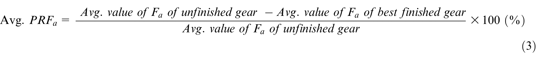
Similar equations can be used to compute avg percentage reduction in total lead error (Avg. PRFβ), in total pitch error (Avg. PRFp), in maximum surface roughness (Avg. PRRmax), in average surface roughness (Avg. PRRa), in tooth-to-tooth composite error (Avg. PRfi), in total composite error (Avg. PRFi), and % reduction in radial runout (PRFrm and PRFrf). All these responses are smaller-the-better type therefore their higher values are desirable. Their limiting value is 100% that is, zero value of that response after finishing by AFF.
Results and discussion
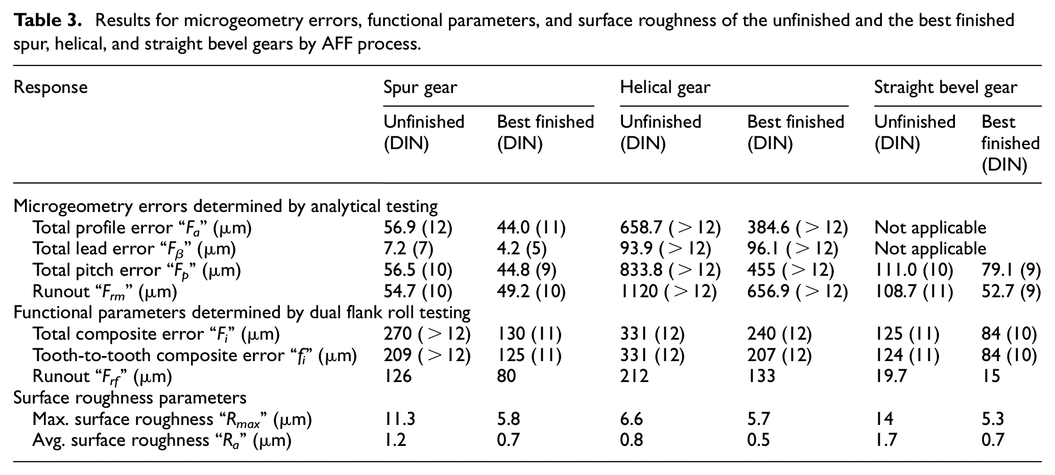
Table 3 presents surface roughness values, microgeometry errors, and functional parameters for the unfinished and the best finished spur, helical, and straight bevel gears by AFF process. Figure 6 shows 3D surface roughness profiles of the unfinished and AFF finished spur gear (Figure 6(a) and (b)), unfinished and AFF finished helical gear (Figure 6(c) and (d)), and unfinished and AFF finished straight bevel gear (Figure 6(e) and (f)). Figure 7 depicts the photographs of spur, helical and straight bevel gears before and after their finishing by AFF. Figure 8 depicts variation in the center-to-center distance (marked as displacement in μm) with rotation angle for the unfinished spur gear (Figure 8(a)), helical gear (Figure 8(c)), and straight bevel gear (Figure 8(e)) and the corresponding best finished spur gear (Figure 8(b)), helical gear (Figure 8(d)), and straight bevel gear (Figure 8(f)). Values of total composite error, tooth-to-tooth composite error, and radial runout are computed from these graphs. Appendix Table A1 presents values of noise and vibrations of the unfinished and the best finished spur and straight bevel gears for different combinations of rotational speed and applied load. Appendix Table A2 presents the same for helical gears. Figures 9 and 10 graphically depict the change in sound pressure level (SPL) and vibrations respectively with the applied load for different rotational speeds for the unfinished and best finished spur gear (Figures 9(a) and 10(a)), for the unfinished helical and best finished helical gear (Figures 9(b) and 10(b)), and for unfinished straight bevel gear and best finished straight bevel gear (Figures 9(c) and 10(c)).
Results for microgeometry errors, functional parameters, and surface roughness of the unfinished and the best finished spur, helical, and straight bevel gears by AFF process.
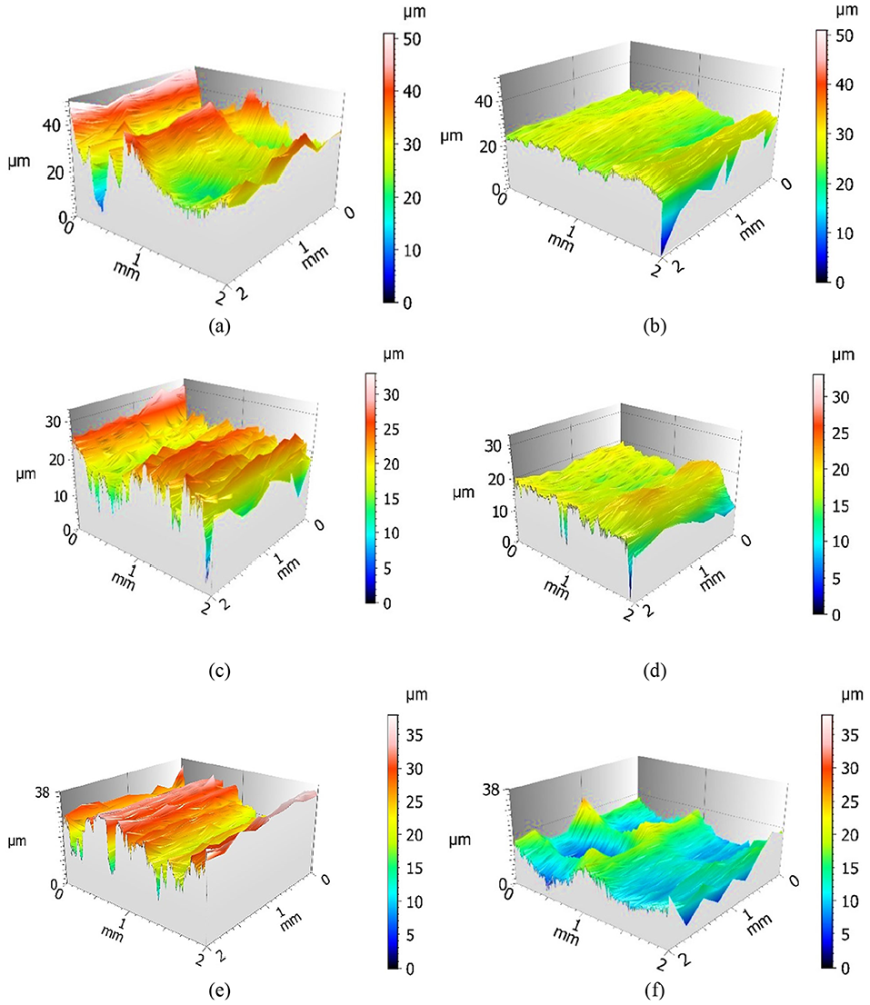
Three-dimensional surface roughness profiles of the tooth flank surface of (a) unfinished spur gear, (b) AFF finished spur gear, (c) unfinished helical gear, (d) AFF finished helical gear, (e) unfinished straight bevel gear, and (f) AFF finished straight bevel gear.
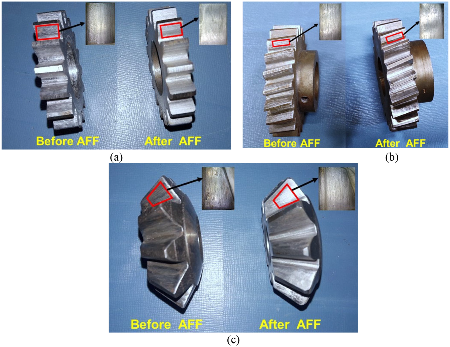
Photograph of (a) spur gear, (b) helical gear, and (c) straight bevel gear, before and after their finishing by AFF.
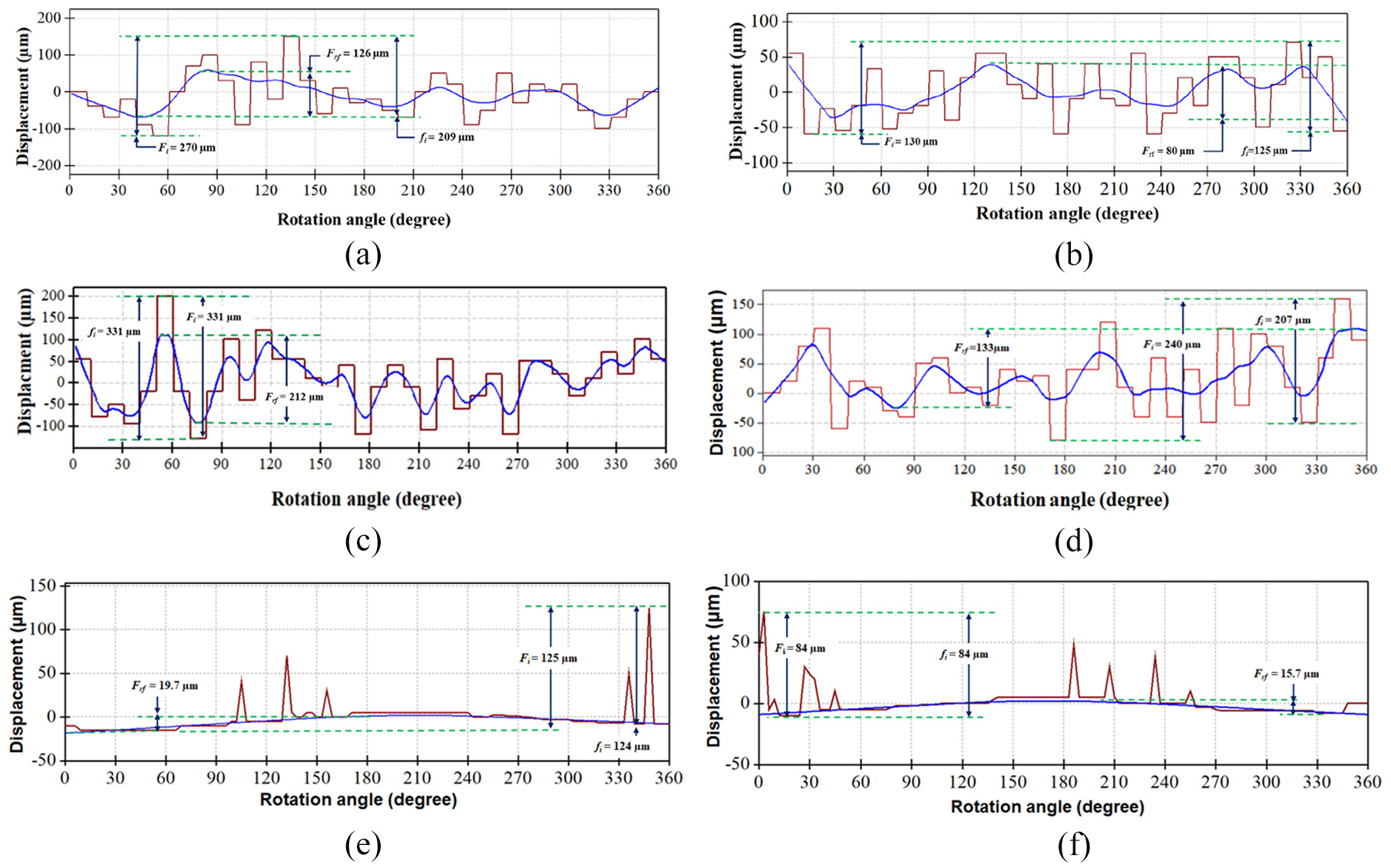
Total composite error “Fi,” tooth-to-tooth composite error “fi,” radial runout “Frf” for the (a) unfinished spur gear,(b) best finished spur gear, (c) unfinished helical gear, (d) best finished helical gear, (e) unfinished straight bevel gear, and (f) best finished straight bevel gear.
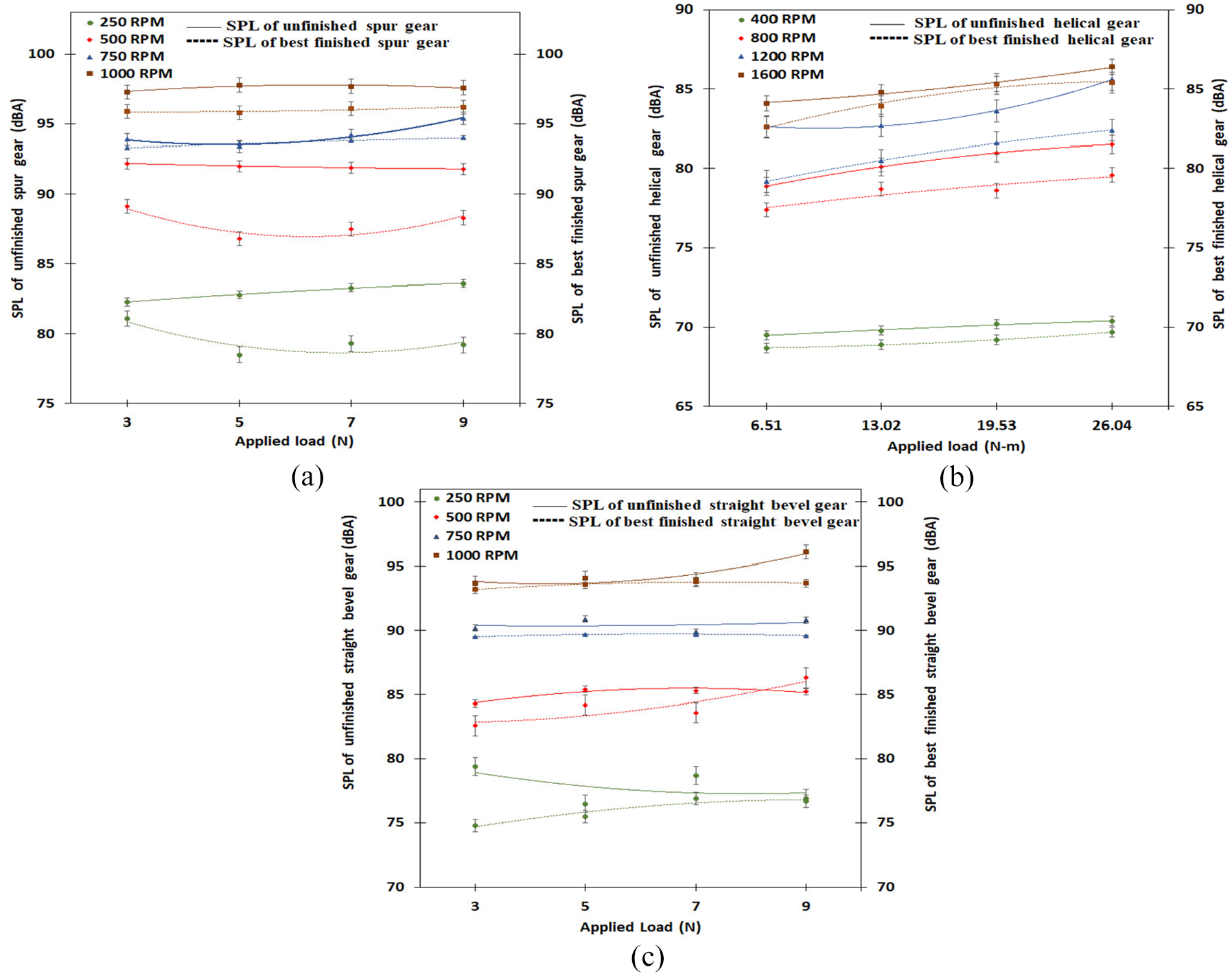
Effect of applied load and rotational speed on sound pressure level (SPL) for the unfinished and the best finished (a) spur gear, (b) helical gear, and (c) straight bevel gear.
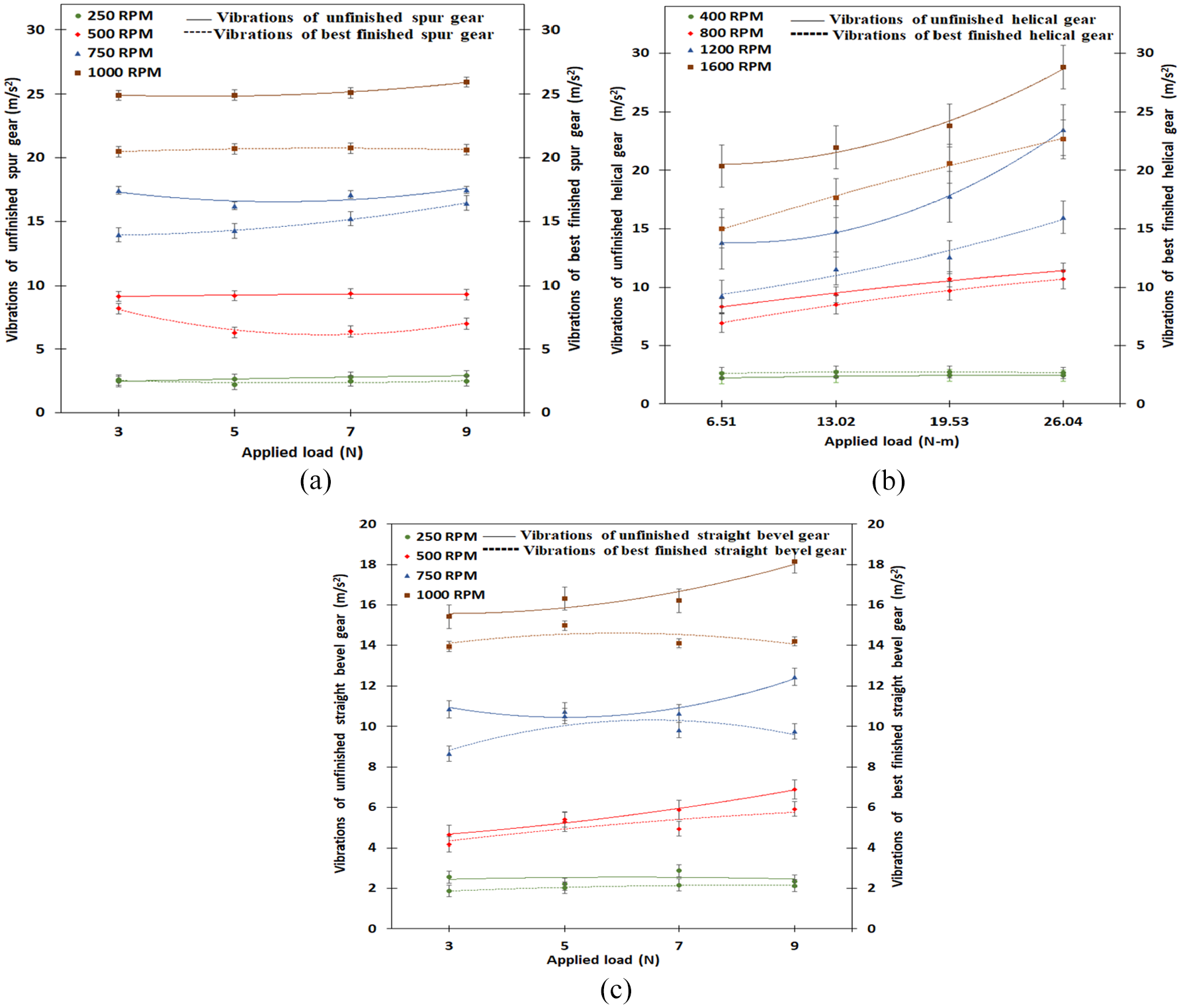
Effect of applied load and rotational speed on vibrations of the unfinished and the best finished (a) spur gear, (b) helical gear, and (c) straight bevel gear.
Following are observations and their explanations after analyzing the result of reduction in microgeometry errors, functional parameters, and surface roughness (Table 3), and reduction in noise and vibrations of the AFF finished spur, helical, and straight bevel gears as compared to corresponding unfinished gears (Figures 9 and 10):
It is evident from Figure 6 that flank surfaces of the unfinished (i.e. before AFF) spur (Figure 6(a)), helical (Figure 6(c)), and straight bevel gears (Figure 6(e)) have high surface roughness peaks. Finishing by AFF process significantly reduces these surface roughness peaks for spur gears (Figure 6(b)), helical gears (Figure 6(d)), and straight bevel gears (Figure 6(f)) thus imparting them smooth surface. Comparison of photographs of flank surfaces of unfinished gears with the AFF finished gears (Figure 7) reveals that flank surface of all three types of gears were very rough but AFF significantly improved quality of their flank surfaces. Reduction in surface roughness peaks gives smooth and uniform meshing of the gears. It increases their contact area enabling the finished gear to offer more resistance to the applied load resulting in smoother power transmission. It also results in less accumulation of the worn debris in the gear drive thus reducing friction-induced vibration and the noise under dry lubrication condition.
AFF reduced total profile error and total lead error for spur and helical gears, total pitch error, and radial runout for spur, helical, and straight bevel gears. This is due to continuous back and forth movement of the finishing medium used in the putty form in AFF process under high extrusion pressure between the intricate tooth spaces, which causes removal of extra materials from gear flank surfaces making profile and lead more accurate in shape and size. It improves tooth spacing and runout and reduces center distance variation. All these factors result in smooth and accurate meshing of the workpiece gear with its master gear during dual flank roll testing and reduce variations in the center-to-center distance. This results in reduction in total composite error, tooth-to-tooth composite error. It can be observed from Table 3 that the radial runout values determined by dual flank roll testing for helical and straight bevel gears are significantly smaller than those determined by analytical testing on the CNC gear metrology machine. This is very significant because roll testing simulates the actual working conditions for a gear by meshing it with the master gear unlike the analytical testing.
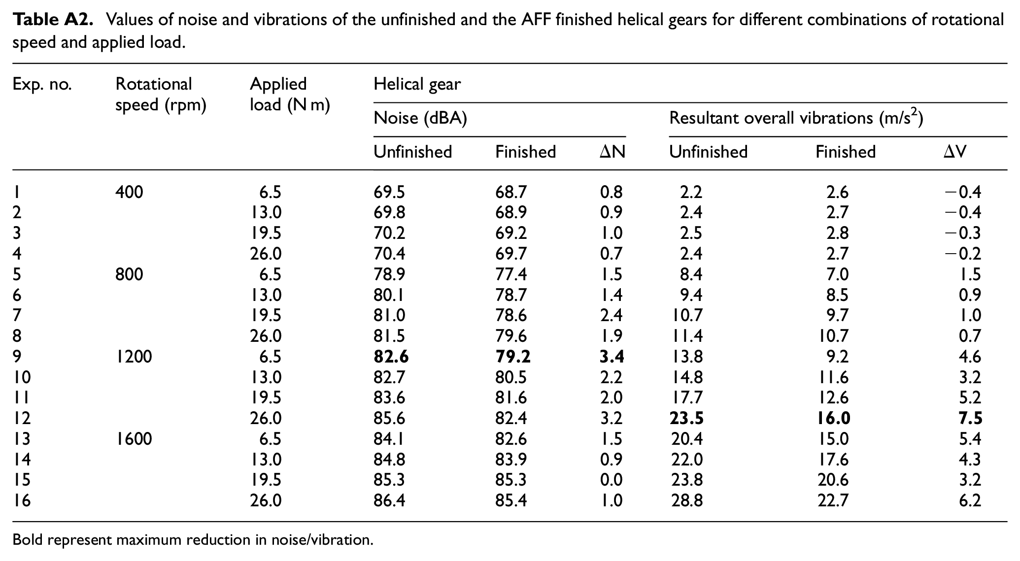
AFF finished gears generated lower noise than their corresponding unfinished gears for all the considered values of load and speed. AFF finished spur, helical, and straight gears showed more reduction in noise at a speed of 500, 1200, and 250 rpm respectively than that at other speed values. Maximum noise reductions obtained for AFF finished gears are: 5.2 dBA occurring at 5 N load (Exp. No. 6 in Appendix Table A1) for spur gear, 3.4 dBA at 6.5 Nm torque (Exp. No. 9 in Appendix Table A2) for helical gear, and 4.6 dBA at 3 N load (Exp. No. 1 in Appendix Table A1) for straight bevel gears that is, maximum noise reduction is more for spur gear than the helical gear due to higher values of the total profile error of helical gear than spur gear for both the unfinished and AFF finished conditions. Reduction in profile error improves conjugate action in both the workpiece and master gear by reducing the deviation during the meshing cycle at high speed and load which contribute to reduce dynamic forces and noise.
Vibration levels of AFF finished spur, helical, and straight bevel gears are lower than their corresponding unfinished gears at all the considered load and speed values (Figure 10(a)–(c)) except for helical gear at 400 rpm (Figure 10(b)). It is evident that amount of reduction in vibration for the AFF finished gears increases with speed. Vibrations of unfinished and AFF finished helical, and spur and straight bevel gears were much higher at 1600 and 1000 rpm respectively for all the values of load than corresponding values at lower speed (Figure 10(a) and (b)). Obtained maximum values of vibration reductions are: 5.3and 4.0 m/s2 for AFF finished spur and straight bevel gears respectively occurring at 1000 rpm speed and 9 N load (Exp. No. 16 in Appendix Table A1), and 7.5 m/s2 at 1200 rpm and26.0 Nm torque (Exp. No. 12 in Appendix Table A2) for AFF finished helical gear. These reductions in the vibrations are due to reduction in functional parameters, total pitch error, and radial runout after finishing all three types of gears by AFF. Reduction of total pitch error, and radial runout decreased non-uniform motion of workpiece gear during its meshing with the master gear which reduces gear vibrations.
Conclusions
This paper reported on reduction of noise and vibrations of cylindrical and conical gears by finishing them by abrasive flow finishing process. Following conclusions can be drawn from this study:
Abrasive flow finishing of cylindrical (i.e. spur and helical) gears decreased their form errors by reducing total profile error and total lead error which reduced their noise and increased their load carrying capacity.
Abrasive flow finishing of cylindrical and conical gears reduced their location errors by decreasing total pitch error and radial runout which enhanced their motion transfer characteristics and transmission accuracy.
Abrasive flow finishing of cylindrical and conical gears considerably reduced maximum and average roughness values of their flank surfaces. This improved contact area of the finished gear with its meshing gear resulting in uniform distribution of forces and in less gear vibrations.
Abrasive flow finishing of cylindrical and conical gears reduced their functional parameters (i.e. total composite error, tooth-to-tooth composite error, and radial runout) which resulted in uniform transmission of motion with low excitation force during their meshing. It leads to lesser whining noise and vibrations.
Reductions in microgeometry errors of abrasive flow finished helical gears were smaller than the abrasive flow finished spur and straight bevel gears due to larger values of microgeometry errors in the unfinished helical gear.
This study proves that abrasive flow finishing is an easy-to-operate and effective process to reduce noise and vibrations of cylindrical and conical gears by simultaneous reduction in their microgeometry errors, functional parameters, and surface roughness parameters.
Footnotes
Appendix
Values of noise and vibrations of the unfinished and the AFF finished helical gears for different combinations of rotational speed and applied load.
| Exp. no. | Rotational speed (rpm) | Appliedload (N m) | Helical gear | |||||
|---|---|---|---|---|---|---|---|---|
| Noise (dBA) | Resultant overall vibrations (m/s2) | |||||||
| Unfinished | Finished | ΔN | Unfinished | Finished | ΔV | |||
| 1 | 400 | 6.5 | 69.5 | 68.7 | 0.8 | 2.2 | 2.6 | −0.4 |
| 2 | 13.0 | 69.8 | 68.9 | 0.9 | 2.4 | 2.7 | −0.4 | |
| 3 | 19.5 | 70.2 | 69.2 | 1.0 | 2.5 | 2.8 | −0.3 | |
| 4 | 26.0 | 70.4 | 69.7 | 0.7 | 2.4 | 2.7 | −0.2 | |
| 5 | 800 | 6.5 | 78.9 | 77.4 | 1.5 | 8.4 | 7.0 | 1.5 |
| 6 | 13.0 | 80.1 | 78.7 | 1.4 | 9.4 | 8.5 | 0.9 | |
| 7 | 19.5 | 81.0 | 78.6 | 2.4 | 10.7 | 9.7 | 1.0 | |
| 8 | 26.0 | 81.5 | 79.6 | 1.9 | 11.4 | 10.7 | 0.7 | |
| 9 | 1200 | 6.5 |
|
|
|
13.8 | 9.2 | 4.6 |
| 10 | 13.0 | 82.7 | 80.5 | 2.2 | 14.8 | 11.6 | 3.2 | |
| 11 | 19.5 | 83.6 | 81.6 | 2.0 | 17.7 | 12.6 | 5.2 | |
| 12 | 26.0 | 85.6 | 82.4 | 3.2 |
|
|
|
|
| 13 | 1600 | 6.5 | 84.1 | 82.6 | 1.5 | 20.4 | 15.0 | 5.4 |
| 14 | 13.0 | 84.8 | 83.9 | 0.9 | 22.0 | 17.6 | 4.3 | |
| 15 | 19.5 | 85.3 | 85.3 | 0.0 | 23.8 | 20.6 | 3.2 | |
| 16 | 26.0 | 86.4 | 85.4 | 1.0 | 28.8 | 22.7 | 6.2 | |
Bold represent maximum reduction in noise/vibration.
Acknowledgements
The authors acknowledge thanks to the DST-FIST New Delhi, India, for providing supports to gear testing and manufacturing facility under the Center of Excellence in Gear Engineering, IIT Indore. The first author acknowledges the generous support of the DST-INSPIRE Fellowship program.
Declaration of conflicting interests
The author(s) declared no potential conflicts of interest with respect to the research, authorship, and/or publication of this article.
Funding
The author(s) received no financial support for the research, authorship, and/or publication of this article.