
Abstract
Compared with the conventional servo press, the direct drive press even has no transmission mechanism, so it has advantages in controllability, precision and energy management. But, the forging capacity of the direct drive press is limited by the power of the linear motor. In this paper, a novel press driven by a tubular permanent magnet linear motor (TPMLM) is presented, and a symmetrical toggle booster mechanism is specially proposed to enhance the forging capacity. The mathematical model of the toggle booster mechanism is established, The TPMLM is designed, and the experimental prototype of the novel press is manufactured. The forging capacity and dynamic characteristics of the press are studied theoretically and experimentally. The results show that the introduction of the symmetrical toggle booster mechanism enriches the dynamic characteristic curve of the press and enhances the forging capacity. Therefore, the structural parameters of the toggle mechanism and the working position of the slider can be adjusted to meet different technological requirements. In addition, based on the research work, three directions are proposed to improve the forging capacity of the novel press. The research contributes to the performance optimization and development of direct drive press.
Keywords
Introduction
With the rapid development of industry, the demand forging is increasing, and the quality requirements of forging are getting higher and higher. China’s forging output reached about 12.08 million tons, and has been the world’s largest producer and consumer of forgings for many years. According to the research institute’s forecast, China’s forging output will reach about 13.56 million tons in 2020. 1 As the most basic equipment in the field of forgings, the press directly determines the performance of forgings.
Servo press offers the flexibility of a hydraulic press (infinite slide speed and position control, availability of press force at any slide position) with the speed, accuracy and reliability of a mechanical press. In addition, servo press has capabilities to improve process conditions and productivity in metal forming. Many scholars have made great contributions to the development of servo press. Osakada et al., 2 Kawamoto et al., 3 and Halicioglu et al. 4 summarized the development of servo press and enumerated the application of servo press in production. In addition, the advantages of various forms of servo press are summarized and the future development is prospected. Halicioglu et al.5,6 designed a servo crank press respectively. Yang et al. 7 has carried on the kinematic and dynamic characteristics design for slider-crank and screw mechanisms. Xie et al. 8 has carried on the optimization research on double toggle mechanical press. Yu et al. 9 and Lu 10 analyzed the kinematics of the servo press of linkage servo press. Halicioglu et al. 11 made a study on the process curve of servo press. Qu 12 designed a non-uniform velocity motion curves for a slider-crank servo press. Kitayama et al. 13 optimized the process curve. Zhang et al. 14 optimized the transfer mechanism of the process curve and connecting rod mechanism. These research provide an important support for the improvement and optimization of servo press.
However, these researches mainly focused on the conventional servo press. The conventional servo press driven by a rotary motor needs a complicated transmission mechanism to convert rotary motion into linear motion, and its structure is complex. Compared with the conventional servo press, the linear motor driven press has many characteristics, such as simple structure, quick response, high positioning accuracy, less mechanical wear, longer tool life, and less vibration. In addition, the accumulated know-hows with the existing presses can be inherited because of the motions. And some research of the conventional servo press can also be applied to the novel press driven by the linear motor. Therefore, it is necessary to study the linear motor driven press and improve its performance effectively.
Nakagava et al. 15 put forward the linear motor press for the first time and summarized the characteristics of the linear motor press, as well as the existing development defects. Beherns et al. 16 summarized the metal forming equipment driven by linear motor and elaborated various forms equipment. Chao et al. 17 and Shengdun et al. 18 pointed out the development key of linear motor driven press. Liang19–21 put forward the idea of a servo press driven by linear motor, and pointed out three topological structures of linear motor. Liang also pointed out that the turbulent linear motor can better balance the normal force than flat plate linear motor, but he manufactured a press driven by four symmetrical flat plate linear motors.
Based on the previous work on conventional servo press, and the work of the press driven by linear motor, it can be seen that the servo press driven by linear motor has certain advantages in controllability with simple structure and produce the maximum load at any stroke position. As shown in Figure 1, the linear motor drives the slider directly. In this mechanism, the slider moves in a straight line, without gear, synchronous belt wheel and other deceleration mechanism; without crank connecting rod, spiral pair and other motion form conversion mechanism; without elbow bar, multi-connecting rod and other force increasing mechanism. However, due to the limitation of linear motor power, the tonnage of the press is very small.
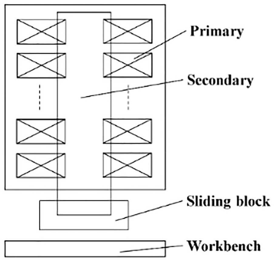
Direct drive mechanism.
In this paper, on the basis of the direct drive mechanism and considering the limitation of the linear motor, a toggle booster mechanism is adopted for the novel press, and the novel press driven by a tubular permanent magnet linear motor (TPMLM) is manufactured. The theoretical analysis and experimental investigation are used to study the toggle booster mechanism structure, TPMLM and the novel press. The mathematical model of the toggle booster mechanism is constructed and its dynamic characteristics are analyzed theoretically. The forging capacity and dynamic characteristics of the novel press are investigated experimentally. Based on the research results, the large forging capacity can be obtained by adjusting the length of the toggle and selecting appropriate workbench position to match the position of the maximum pressure of slider. In addition, based on the research work, there are three directions that are proposed to improve the forging capacity of direct driven press.
The mathematical model and theoretical calculation
The structure of the novel press
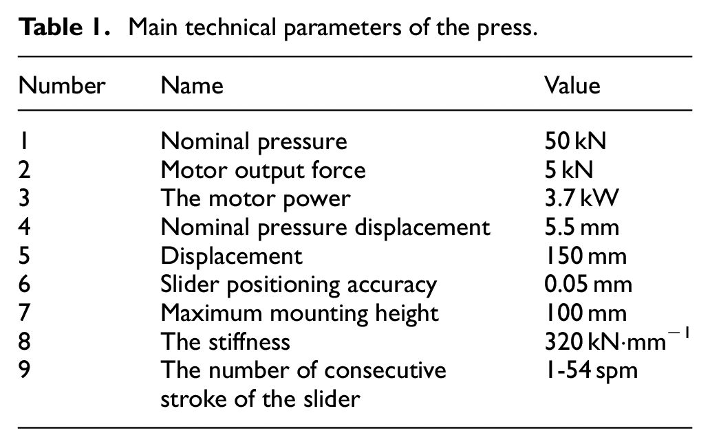
As shown in Figure 2, the novel press is mainly composed of a combination body, a tubular linear motor, a toggle booster mechanism and a sliding block. The combination body consists of three main structural parts (base, stand column, and beam), which are connected to form a closed frame by four tensioning bolts. The combination body adopts box plate welding structure to enhance the rigidity and reduce the weight. The motor is mounted in the combination body. The actuator track is on the stand column to connect the combination body and the sliding block. So, the motor can connect with the slider through a two-steps toggle booster mechanism. In addition, a nitrogen balance system and a counterweight block (not in the picture) are used to balance the weight of slider and shaft to reduce the load on the motor and ensure the smooth operation of the press. The main technical parameters of the novel press are shown in the Table 1.
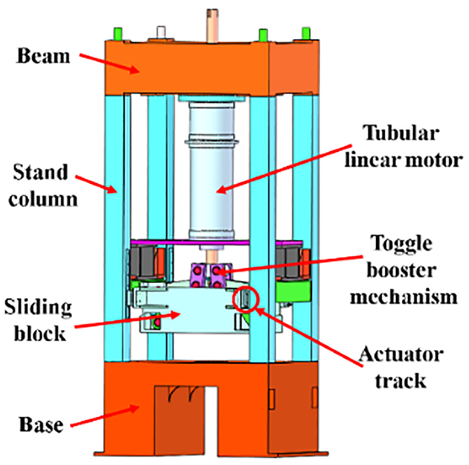
3D model of the direct drive press (not including balanced system).
Main technical parameters of the press.
The symmetrical toggle booster mechanism
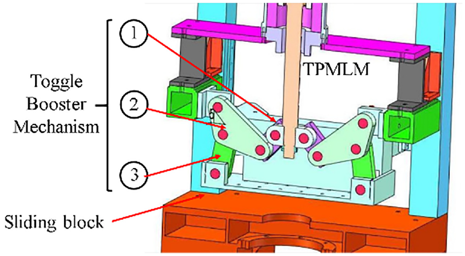
The introduction of the symmetrical toggle booster mechanism can not only amplify the force of the motor, but also effectively stabilize the motion. Figure 3 shows the sectional view of the symmetrical toggle booster mechanism. This consists of three parts and is hinged by shafts fitted with self-lubricating graphite bearings. The force is input from the motor and output from the slider.
Sectional view of the symmetrical toggle booster mechanism.
In addition, as shown in Figure 4, half of the structure is obtained to establish a mathematical model due to the symmetry. The mechanism is simplified to rod-a, rod-b, rod-c, rod-e, and rod-f, and also contains angle-α, angle-γ, angle-
Structural dimension diagram of the half structure of the symmetrical toggle booster mechanism.
In general, the mathematical expressions between the rods are obtained as follow.


Make:
Make:
Thus, the equation (4) can be simplified as follows:

So, the angle-
In addition, in the triangle composed of rods-a, rod-b, and length-(a + b − s), the cosine formula is used to obtain the relationship between the rod-a and rod-b:

Expand and simplify equation (7), get equation (8) as follow:
Make:
Thus, equation (8) can be simplified as equation (9).

So, the mathematical model of the slider is obtained.
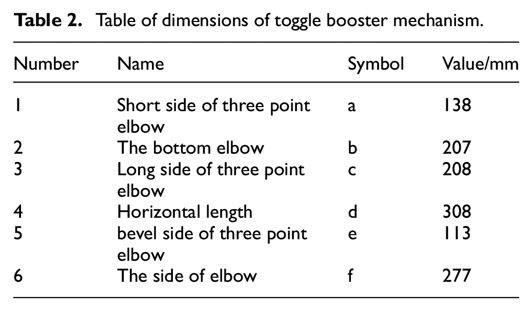
In the above calculation, the unknowns are s, l, α, β, and γ. The βand γ are eliminated in the calculation. α can be represented by the equation (6). So, the relation between the slider displacement-s and the motor displacement-l can be obtained indirectly, and the velocity relation can be established by differentiating the displacement relation in time. According to the actual situation of the project and the demand for increasing force multiple, the optimal size of each elbow bar can be obtained as shown in Table 2.
Table of dimensions of toggle booster mechanism.
As shown in Figure 5, these are the theoretical dynamic characteristics between the slider and the motor. From Figure 5(a), when the position of the slider is after 40 mm, the position of the slider is linearly related to the position of the shaft. From Figure 5(b), when the position of the shaft is between 100 mm and 220 mm, the speed of the slider is linearly related to the position of the slider. From Figure 5(c), when the positon of the slider is after 40 mm, the magnification of the force tends to be constant. Theoretically, the reasonable range of the position of the slider can ensure that the press has a stable forging capacity and dynamic characteristics, which has a very effective advantage for forging process.
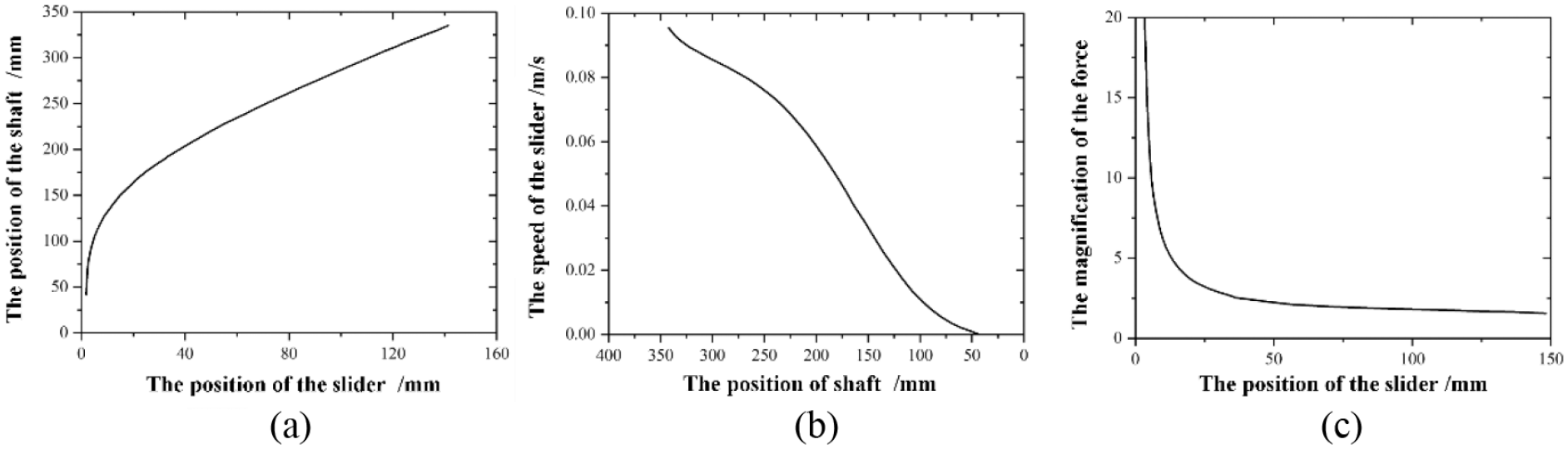
The theoretical motion calculation between the slider and the motor: (a) the position diagram of the slider and the shaft, (b) the diagram of position of the shaft and the speed of the slider, and (c) the diagram of the position of the slider and the magnification of force).
The tubular permanent magnet linear motor (TPMLM)
The TPMLM is the only power source. Its structure model is shown in Figure 6. The tubular structure can overcome the unilateral magnetic attraction and keep the balance on the radial plane.24–26 The stator is arranged by magnetic steel and coil, and it carries on the magnetic field transmission through the magnetic steel. The shaft is arranged by permanent magnet and iron core to complete the output of the force, and the permanent magnet is mounted on the shaft and moves with the motor.
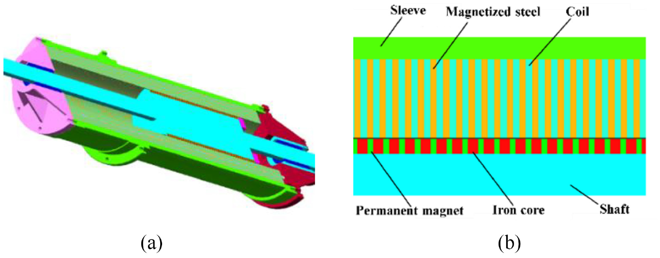
Schematic diagram of the TPMLM: (a) sketch diagram of section structure of TPMLM and (b) schematic diagram of actor, stator and permanent magnet in the TPMLM.
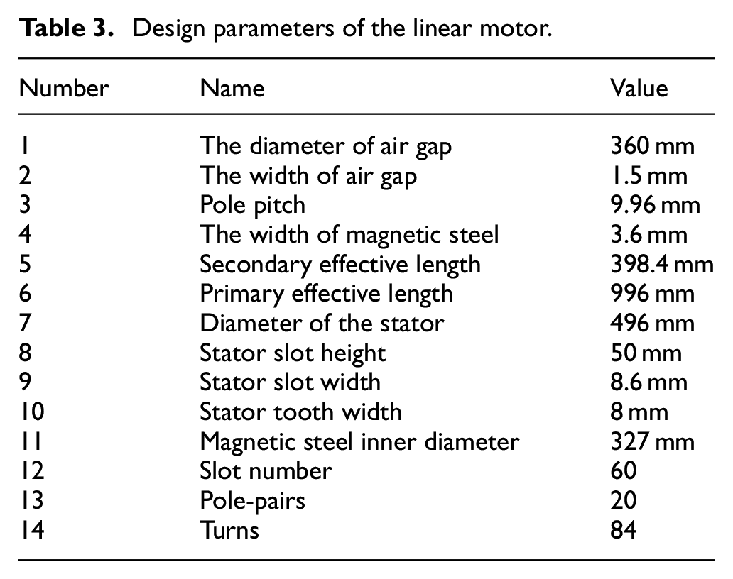
The basic theories of ac servo permanent magnet linear motor and rotary permanent magnet motor are similar. They both transfer energy through the air gap between the stator and rotor, so as to convert electrical energy into mechanical energy.22,23 In addition, the main technical parameters of the linear motor calculated are shown in Table 3.
Design parameters of the linear motor.
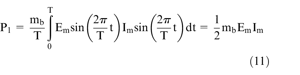
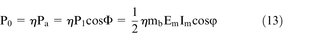
The output power P1 can be expressed as Formula (11); Since there is a phase difference between the input current of the motor and the back electromotive force, it can be seen that the active power Pa of the motor is equation (12). Considering the efficiency of the motor, the output power of the motor is formula (13).

Where,
The back electromotive force is calculated by the following formula.


Where, f is the input current frequency, Hz; N is the number of turns of winding; kw is the armature base wave winding coefficient; Φi is the flux of the armature reaction, Wb; Bm is the average field density of motor air gap, T; Dm is the diameter of the air gap, mm; τ is the pole pitch, mm.
The output force of the linear motor can be expressed as:
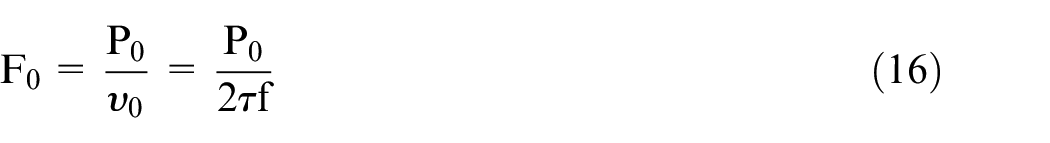
Where,
This simplifies to the following equation
Where,
Experiments and results
The experimental test platform is shown in Figure 7. In the novel press, the main structure, toggle booster mechanism and TPMLM are manufactured. In addition to the novel press, the whole platform also includes sensors, frequency conversion controller (Yaskawa inverter), PC and oscilloscope.
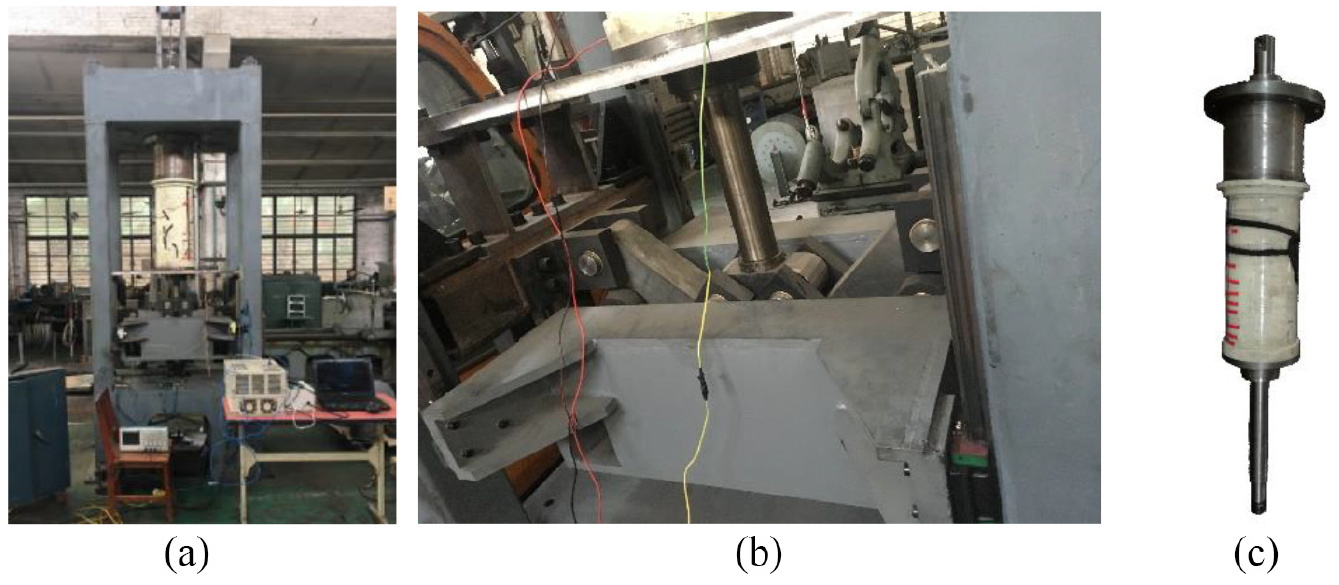
Experiment platform for press machine: (a) novel press, (b) toggle booster mechanism, and (c) TPMLM.
The press is installed with four sensors, as shown in Figure 8, including three displacement sensors and one force sensor. Sensors 1, 2, and 3 are all displacement sensors. The displacement sensor 1 only measures the displacement of the motor. The displacement sensors 2 and 3 measure the displacement of the slider. Sensor 4 is a force sensor and tests the output force. The top of the force sensor is connected is the slider, and the bottom is connected with the mold. The deformation of the force sensor represents the characteristics and magnitude of the force of the slider.
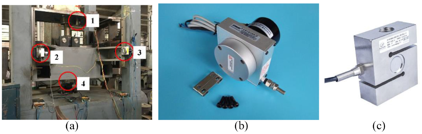
Experimental testing apparatus: (a) sensor position, (b) displacement sensor, and (c) force sensor.
Movement experiment
The displacement of the slider is measured in the different stamping. As shown in Figure 9. When the stamping is 60 spm (stamping per minute), the max displacement is about 15 mm; When the stamping is 30 spm, the max displacement is about 27 mm; When the stamping is 15 spm, the max displacement is about 55 mm; When stamping is single, the max displacement is about 80 mm. This suggests that the max displacement is sacrificed to achieve high frequency stamping when the power of the linear motor is constant.
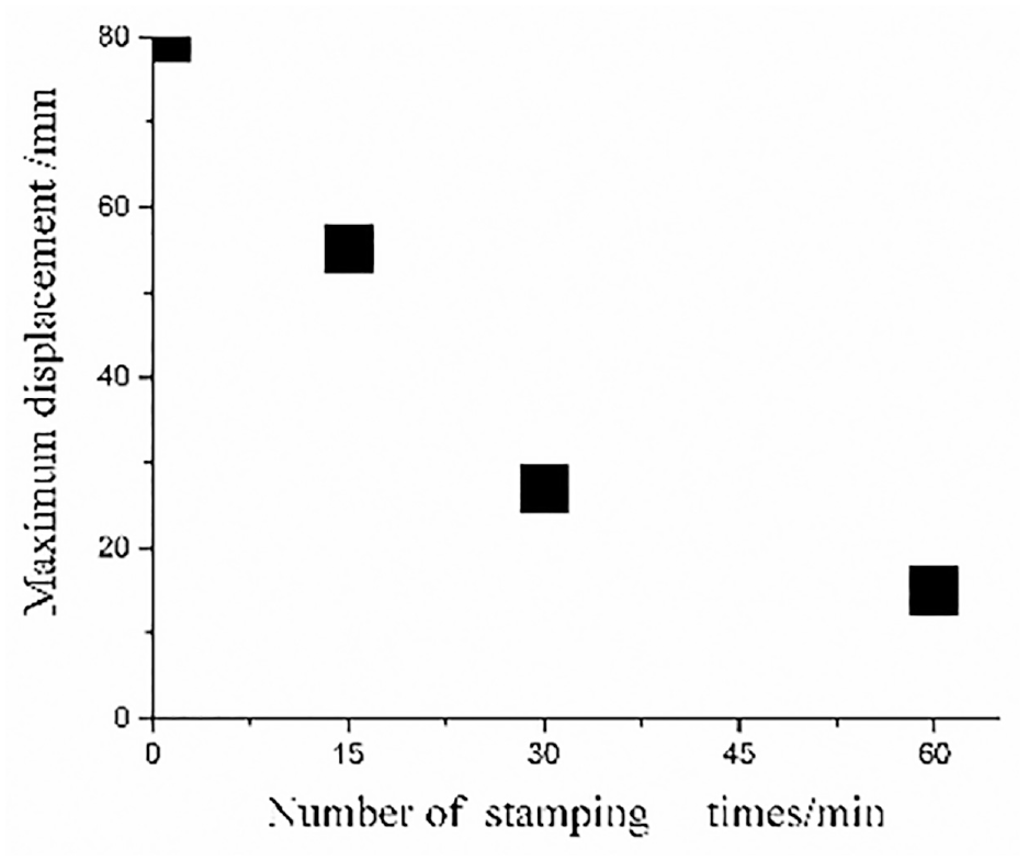
The max displacement of the slider in different stamping.
Figures 10 and 11 are combined to explore the motion relationship between the slider and the motor. Figures 10 and 11 respectively show the displacement of the slider and the motor when single stamping. The displacement variation of the slider is about 80 mm, and the displacement variation of the motor is about 345 mm. The displacement variation time of the slider is about 5 s, while the time of the motor is about 9 s. It can be seen that at the moment of 11 s, the slider has basically reached the max displacement and the displacement variation of the motor is 180 mm. After that, the motor continues to move, but the slider barely moved (probably in the lower limit position). This indicates that influence of motor on slider is suddenly drops (theoretically approaching zero) and the force of slider is likely to increase dramatically (theoretically infinite).
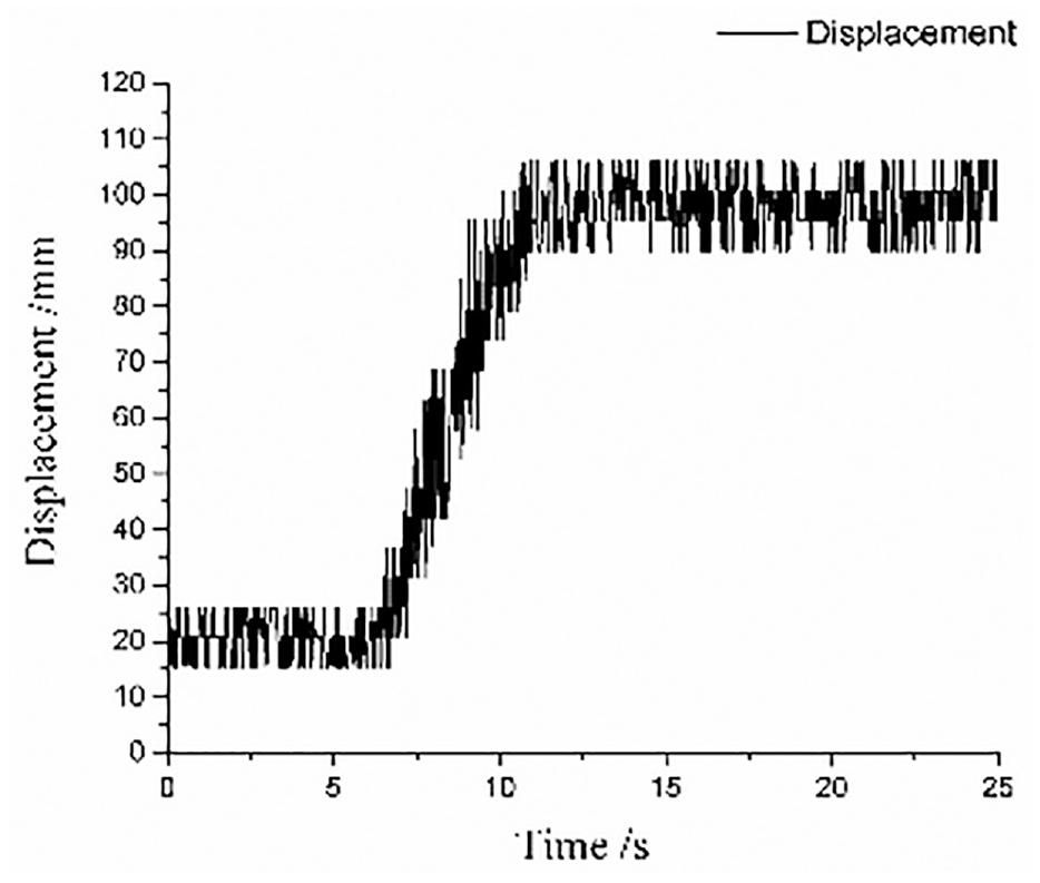
The displacement variation of the slider in single stamping.
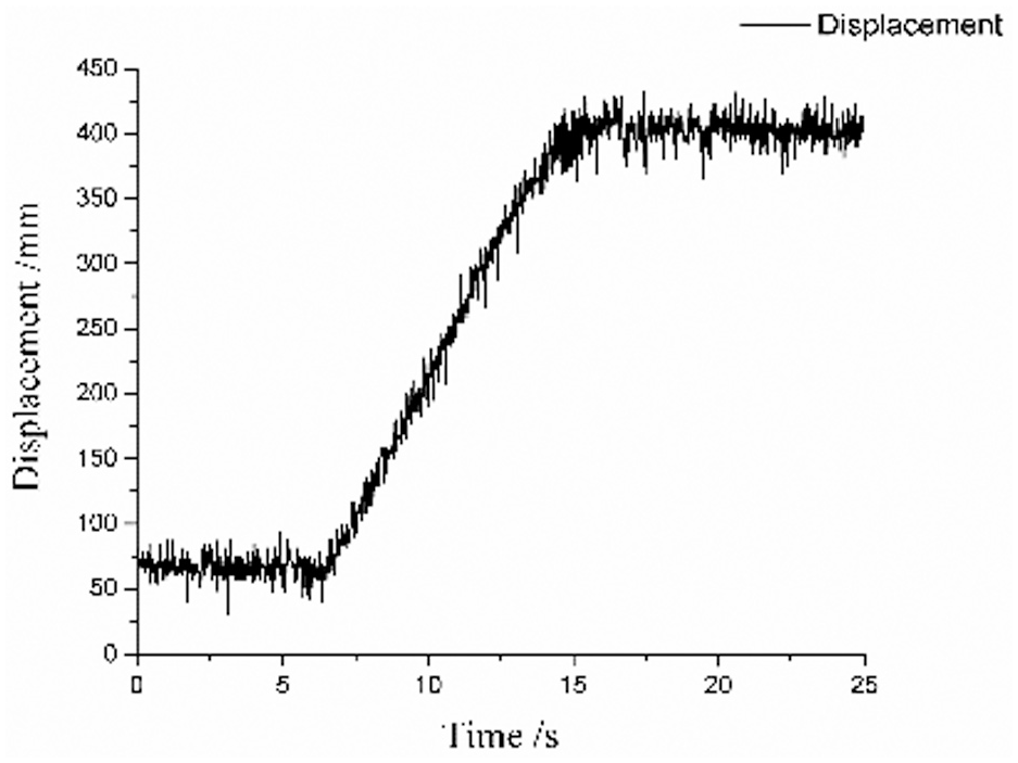
The displacement variation of the motor in single stamping.
Therefore, during the time from 6 s to 11 s (about 5 s), the motion of the slider is obvious. The ratio of the displacement variation of motor to the displacement variation of slider can be calculated, I = 2.25, calculated by equation 8.
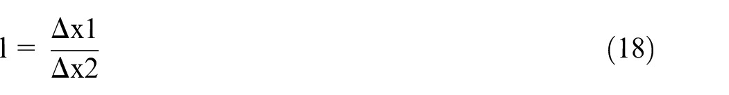
where: I, the ratio of the displacement variation of motor to the displacement variation of slider; △x1, the displacement variation of motor, mm; △x2, the displacement variation of slider, mm.
In addition, from Figure 12, this diagram explains the velocity of the slider at different position, and the theoretical calculation and the experimental results are basically consistent. As the slider moves downward, the speed of the slider gradually decreases, and when it approaches the lower limit position, the speed tends to 0. This also means that the slider is barely moving. Therefore, the appropriate slider position can be selected according the speed requirements of different processes.
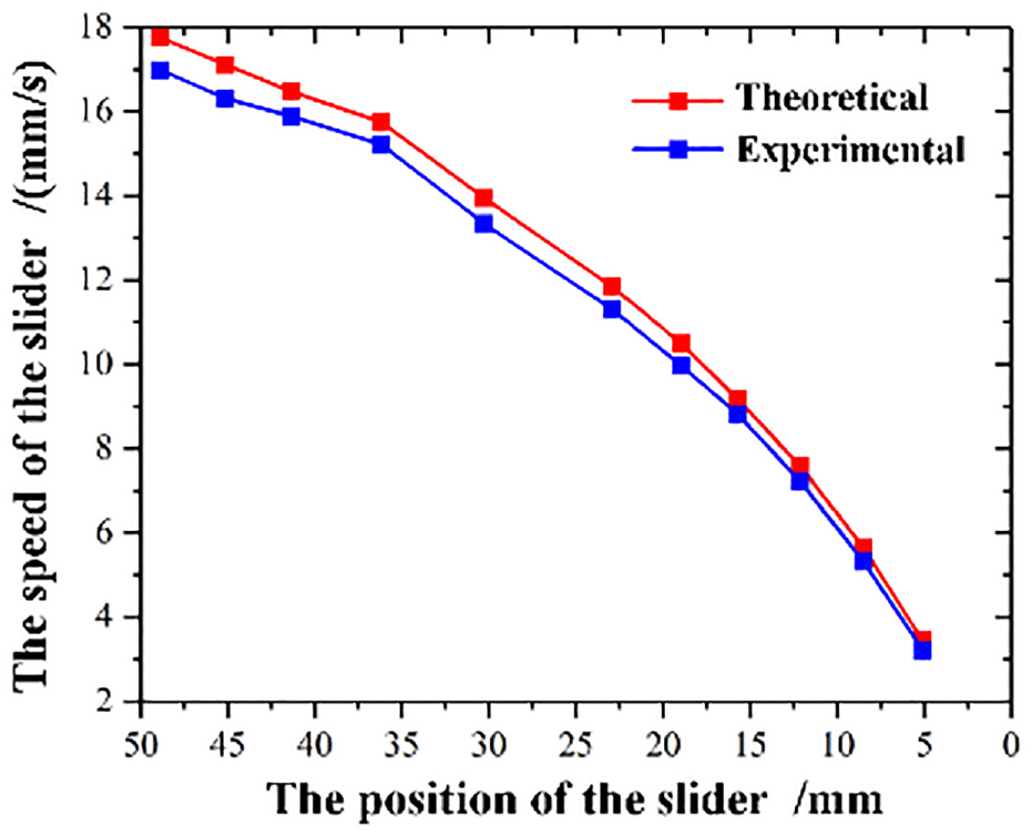
The speed of the slider at different position (at same excitation current).
As shown in Figure 13, this diagram illustrates the speed of the slider at different excitation current frequency, and the theoretical calcuation and practical results are basically consistent. The velocity increases gradually with firequency and It’s a proportional relationship. So, the exictation current frequency can be selected reasonable according to the actual process requirements.
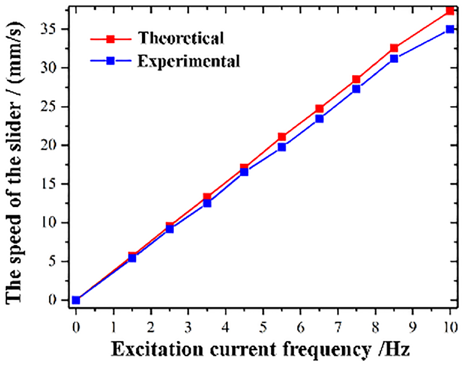
The speed of the slider at different excitation current frequeny.
Dynamic test
As shown in Figure 14(a), this is a test device for force experiment. The top of the sensor is connected to the slider, and the bottom is connected to the mold. The test is to complete the sample processing to obtain the value of the force in the processing, and the stamping result of the plate is shown in Figure 14(b). After that, the current continues to increase, which forces the force to increase to obtain a relatively large force in order to test the forging capacity of the press.
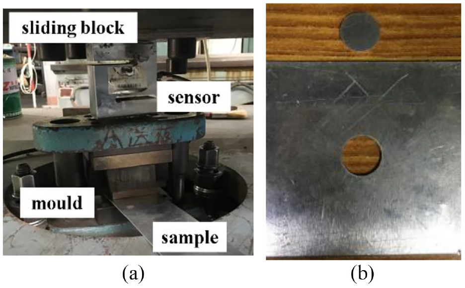
Mechanical testing device and sample: (a) mechanical testing device and (b) sample.
As shown in Figure 15, the curve represents the magnitude of the force in the test. When the time is between 0 s and 1 s, the slider is not yet moving, the force is initial mechanical resistance (about 0.8 kN). When the time is between 1 s and 2 s, the slider is moving but does not touch the sample, the force is the total frictional resistance (about 3 kN). When it comes into contact with the sample at the moment of 2 s, the force starts to increase, and the sample starts to deform. At the moment of 4 s, the processing is completed, the max force of processing is obtained (about 8 kN, the growth rate of force in processing is 2.5 kN/s). After processing, the supply current of the motor goes upfour4 times, and the average force increases to 11.8 kN, 14 kN, 16 kN, and 17 kN respectively. In addition, a relatively large force is about 19 kN. Then, the force decreases as the current decreases. At the moment of 9 s, the slider activates a quick return and the force decreases sharply.
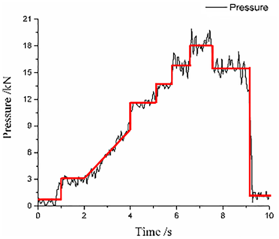
Force curve.
As shown in Figure 16, the theoretical calculation and the experimental result are basically consistent. It can be found that the force is almost proportional to the current (less than 4 A). After the current 4 A, the trend of force growth gradually decreases (especially after 8 A). It can be inferred that as the current reaches a certain level, the force will hardly increase. In addition, in the case of meeting the requirements of the process, the use of lower current to complete can save energy.
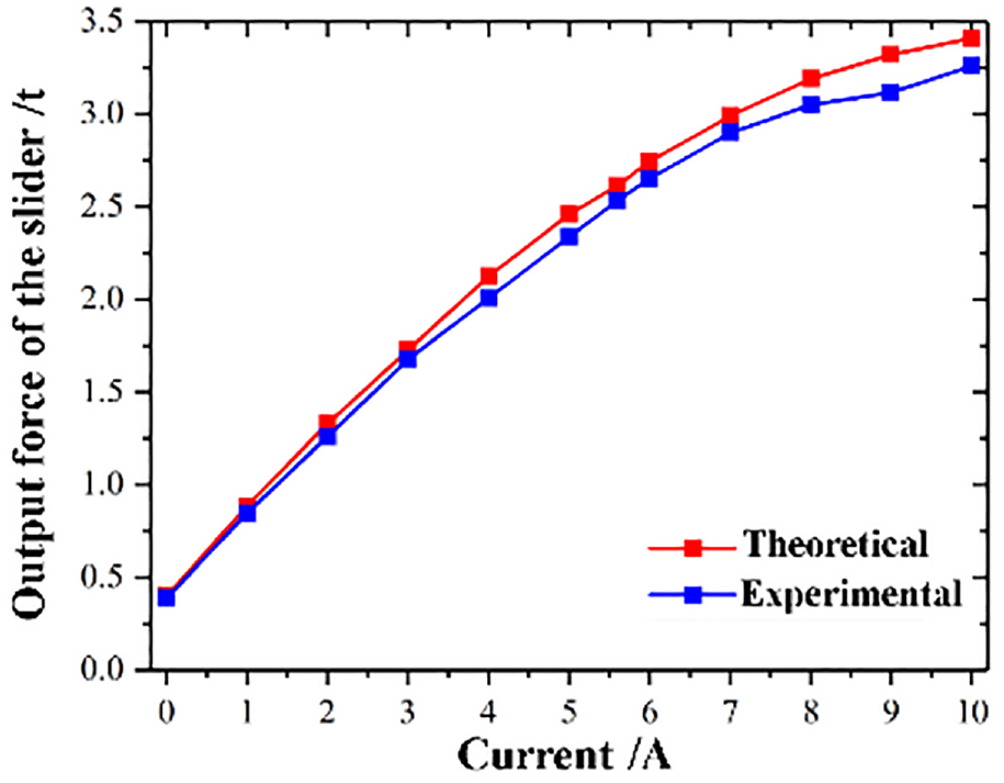
The output force of slider at different excitation current (at same position).
As shown in Figure 17, this is a diagram that clarifies the relationship between the position and the force of the slide. The smaller the position value indicates that the slider is closer to the lower limit position. From the picture, it can be seen that the curve of the force changes sharply. When a relatively smooth force is required, the slider can be adjusted to operate between 30 mm and 55 mm. When a relatively large change of the force is required, the slider can be adjusted to operate between 10 mm and 30 mm. When a sharply large change of the force is required, the slider can be adjusted to operate between near 0 mm and 10 mm. Therefore, the working position of the slider can be adjusted for different process requirements, which can effectively improve efficiency and the forging quality.
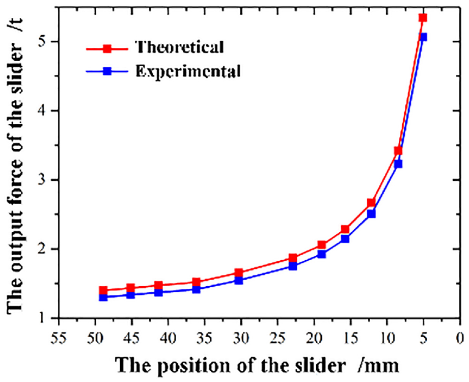
The output force of slider at different position (at same excitation current).
Conclusion
In the novel press, the magnification can be changed by the toggle booster mechanism, and select an appropriate workbench position to match the position of maximum pressure to obtain a large forging capacity. In addition, based on the research work, the following suggestions are put forward to improve the forging capacity of the novel press.
1. Adopt high power drive motor.
Under the existing design and manufacturing conditions, the more powerful TPMLM can be developed, which can directly and effectively improve the forging capacity.
2. Adopt high multiple toggle booster mechanism.
Adjusting the size of the rods and adopting multi-steps toggle booster mechanism can change the magnification, which can indirectly and effectively improve the forging capacity.
3. Take advantage of the idea of decentralized multi-dynamics.
By developing a reasonable synchronous control system, the structure can be extended (Figure 18), which can greatly improve the forging capacity.
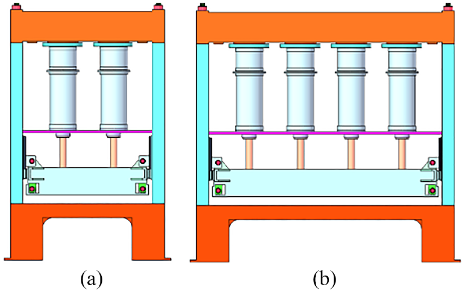
The expanded form: (a) press with double TPMLM structure and (b) Press with multiple TPMLM structure.
Footnotes
Declaration of conflicting interests
The author(s) declared no potential conflicts of interest with respect to the research, authorship, and/or publication of this article.
Funding
The author(s) disclosed receipt of the following financial support for the research, authorship, and/or publication of this article: The present work is financially supported by the National Natural Science Foundation of China (51335009) and State Key Laboratory for Mechanical Behavior of Materials (1991DA105206).