
Abstract
Previous studies of the shearing process demonstrated that clearance and shear rate are the most influential parameters on the geometry of sheared billets. This paper illustrates a parametric numerical study of the impact of these parameters on the quality of the shear surface using the finite element simulation of shearing. In order to account for interactions between stress state evolution and the associated heating during shearing, a fully coupled thermo-mechanical simulation method was adopted. The influence of stress state, strain rate, and temperature on the material behavior were taken into account by using Johnson-Cook plasticity and ductile failure models. Many simulations were carried out involving diverse shear rates and shear clearances. The relationship between the parameters of shear surface geometry and the temperature was illustrated and proven. Contrary to the expectation of high-speed shearing performance, a burr free smooth shear surface was found using a low shear rate. This study illustrates a numerical strategy to determine the best shear clearance-rate set for aluminum alloy Al7075-T6 bars that minimizes the shear surface defects.
Introduction
The rupture of materials can be classified into brittle and ductile. Glass and ceramic are usually modeled with brittle rupture models1–3 while steel and aluminum are modeled by ductile rupture models.4,5 This study investigates the ductile rupture of aluminum bars by shearing process. It is possible to compute rupture with damage models as long as the damage considered is concentrated on a small area, keeping in mind that the choice of the damage model should be appropriate to the studied process and material in order to obtain accurate results.
Damage modeling approaches are generally classified as uncoupled or coupled. The first method, the uncoupled approach, aims to calculate the damage distribution without taking into account its effect on hardening behavior. One example of this model is the Oyane et al. 6 damage model which has been proven accurate in predicting ductile damage in bulk metal processes. It relates the volume of pores during deformation to an integral function of stress triaxiality.
The second method, the coupled approach, assumes interaction between plasticity and damage behavior. Models using this approach, such as the Lemaitre model, 7 have shown their ability to predict damage in the simulation of metal forming and cutting processes.
Flow stress and failure mechanisms, on the other hand, depend on temperature parameter. This fact is taken into account in the Johnson-Cook material model.8,9 This model is commonly used in the simulation of machining and metal forming processes. It calculates damage strains as a function of triaxiality, strain rate, and temperature.
Johnson-Cook material modeling was found to be appropriate in the simulation of shearing, 10 machining,11,12 and ballistic perforation.13,14 Its formulation is relatively simple to implement because of the independency between plastic and damage descriptive equations. Many authors have demonstrated the suitability of the Johnson-Cook model to simulate the forming and cutting processes of aluminum, copper, and titanium alloys.15–17 The common method to identify the parameters of Johnson-Cook models is the split Hopkinson pressure bar (SHPB) test. 18
Numerous numerical researches investigated aluminum sheet shearing using damage models. 19 They studied the effect of shear parameters such us shear clearance, edge radius, and damage factor. 20 The influence of shear speed on the quality of shape and edge-face of sheared pure aluminum disk and ring shearing was proven. 21 The conclusion the authors came up with is that smaller clearance and higher shear rate are needed to produce a better edge-face quality. Others have examined the effect of notch shear cutting on the sheared edge-face. 22 Also the effect of the cutting angle on the microstructural changes of the material during sheet shearing was investigated. 23 In comparison to the vast experimental and numerical researches on improving sheet shearing, only a scarce number of studies were found on bar shearing. Among this, Maiti 24 has established a numerical study and deduced the influence of a number of process parameters on the sheared edge-profile and crack extension behavior by double bar shearing. These parameters are aspect ratio, punch width, tool clearance, load distribution, and axial force. An experimental study on aluminum bar shearing was also performed by Behrens et al. 25 to investigate the influence of microstructural condition, clearance, and shear rate on the shear plane quality of various aluminum alloys. A small clearance was found to have a positive effect on the inclination angle. On the other hand, shear rate effect is dependent on the microstructure of the sheared alloy.
An adequate material behavior modeling that considers the influence of stress state and temperature on plasticity and fracture mechanisms was necessary for a valuable numerical modeling of shearing. 26 Moakhar et al. 26 used Hooputra et al.’s 27 ductile damage model and calibrated it using temperature and a triaxiality dependent experimental procedure.
The geometry of sheared billets can exhibit some imperfections that have a negative impact on the result of forging processes. To ensure the quality of these parts, a rework process is often required after bar shearing. The occurrence of these defects is related to the microstructural characteristics of the bar material and to the shear parameters, in particular clearance and shear rate. 25 Automation of bar shearing is dependent on the understanding of the influence of these parameters on the damage mechanisms of the bar metal.
In the bar shearing process, plastic work in the shear zone induces temperature growth which influences material mechanical characteristics. Thus, interactions between mechanical and thermal fields have to be considered in the simulation of bar shearing.
In this work, numerical shearing models were developed based on the thermo-mechanical coupling in order to investigate the effect of the most influential shear parameters on bar shear quality. The material studied is the aluminum alloy Al7075-T6 since aluminum is the most nonferrous metal used in metallic production. The material behavior was modeled using Johnson-Cook plasticity and failure models. A parametric study was conducted to analyze the shear quality and temperature evolution over a range of shear-clearance combinations.
Principle of coupled thermo-mechanical finite elements for shearing
The finite element method (FEM) was applied to study shearing and to predict billet geometry. 28 Most of the previous studies did not consider the coupling between mechanical and thermal phenomena, despite the fact that elevated shear velocity induces adiabatic heating in the shear zone and consequently modifies the mechanical properties of the bar material. Thus, a strong coupling between mechanical and thermal domains must be considered in shearing simulations. In addition, many other sources of nonlinearity exist: geometric nonlinearity because of large deformations, material nonlinearity because of the transfer from elastic to plastic and from undamaged to damaged behavior, and boundary conditions nonlinearity due to friction between tool and bar and between sectioned bar surfaces.
Below, the main governing equations of the coupled thermo-mechanical system are presented.
Mechanical governing equations
The mechanical dynamic equilibrium is defined with the following motion equation:

Where σ is the stress tensor obtained from the constitutive law, Fv is the body force density, ρ is the density, ü is the acceleration and

Where ε is the strain, εel is the elastic strain, εpl is the plastic strain, and εth is the thermal strain.
To account for the strain rate ε and the temperature T dependence of the deformation behavior of the metal, the flow stress constitutive equation was formulated as follows:

The contact conditions were modeled with the Coulomb-Tresca friction model:
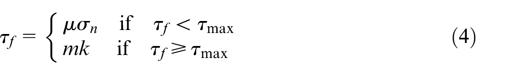
Where τ f is the shear friction stress, μ is the Coulomb friction coefficient, σ n is the contact normal stress, m is the constant shear friction factor, k is the shear flow stress and τmax is the maximal shear stress. The commonly used method to determine the friction coefficients is the ring compression test. 29
The variational equation for the mechanical problem is formulated using the virtual work principle, such that for an arbitrary displacement Δδ the sum of internal and external work vanishes:
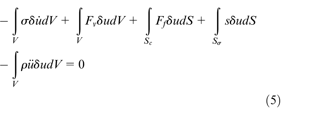
Where Ff is friction force vector on the surface Sc and s is the stress vector on the surface Sσ. The considered solid has the volume V and the surface
Thermal governing equations
The thermal energy balance is resumed with the following equation:

Where Cp is the specific heat, Ṫ is temperature time derivative, div is the divergence operator, k is the isotropic temperature dependent thermal conductivity and Q is the internal heat generation rate per unit-deformed volume. The main internal sources of thermal energy are friction and plastic deformations.

Where Qp is the heat flux generated from plastic work and Qf is the heat flux generated from friction work.
The heat flux generated from plastic work is expressed as follows:

Where
The energy balance can be rewritten in the weak variational form as following:
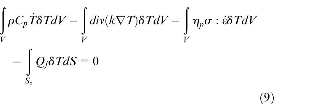
Where δT is an arbitrary function of temperature.
Finite element formulation
The mechanical semi-discrete equilibrium equation can be rewritten as a summation over all finite elements of the model as follows:

Where M is the mass matrix, and [Fext] and [Fint] are the external and internal force vectors, respectively.
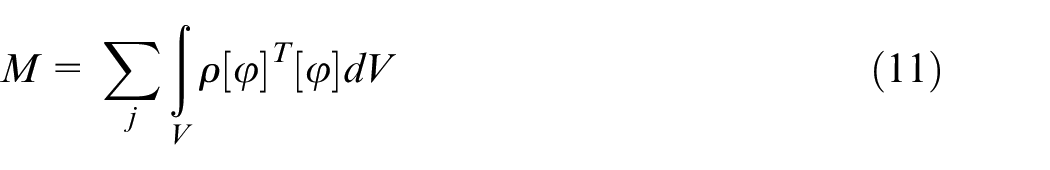
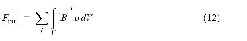
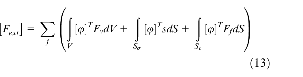
Where [ϕ] is the shape matrix of a brick element and
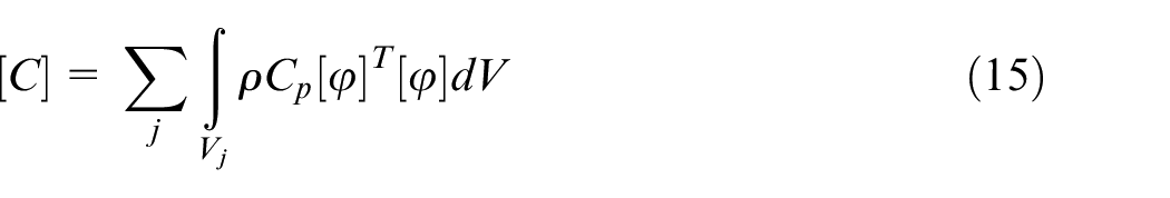
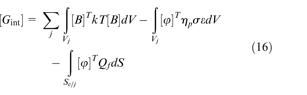
The thermal semi-discrete equilibrium equation can be rewritten in the form as a summation over all finite elements of the model as follows:

Where [C] is the heat capacitance matrix, and [Gint] and [Gext] are the internal and the external heat flux matrices, respectively. In this study, there is no external heat source.

Shear parameters
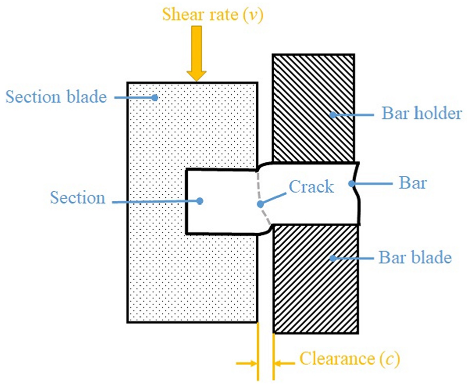
Shearing methods are distinguished through five criterions 30 : kinematic of the die movement, stress state in the shear zone, tool arrangement, shear rate, and shear temperature. The general principle of shearing and its tooling are shown in Figure 1.
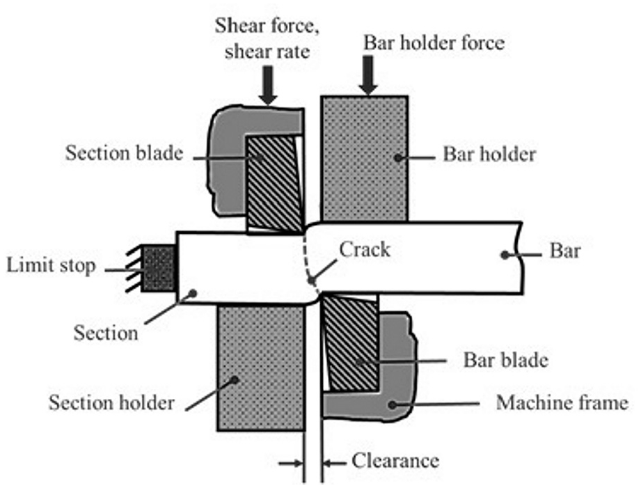
Shearing tool setup.
The pressure exerted by the moving blade causes a plastic deformation of the metal in the shear zone, which is located between the blades. The rupture occurs when the mechanical stress and the deformation reach the breaking point. The crack propagates between the cutting edges of the section blade and the bar blade. The shearing result depends on the setting of three basic elements: work piece, tool, and machine. In Table 1, the most relevant parameters of each element for shear quality are presented. 31
Most relevant shear parameters for shear quality.
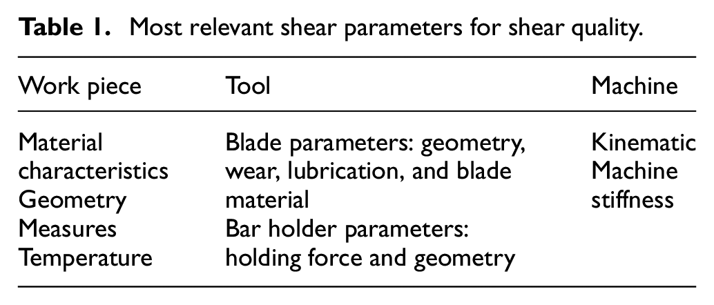
According to Behrens et al., 25 shear quality is mostly influenced by the shear clearance, the shear rate, and the microstructural condition of the bar material. Altan et al. 32 have indicated that blade edge radius, clearance angle, and billet temperature are also important factors that affect sheared billet quality. In the following, some of these parameters are detailed.
Shear clearance
Shear clearance (c) is the distance between the blades on the perpendicular plane to the direction of the blade movement. The wideness of the shear zone depends on the wideness of the clearance. When the clearance is small, the zone of the plastic deformation is also small and the metal is highly stressed in this area. Thus, shear clearance is the most influential parameter on the shear surface appearance and it has to be determined according to the bar material properties.
In the case of aluminum bar shearing, small clearance is required. 30 Clearance form in round bar shearing depends on the blade geometry. Blades can be straight, round, and sharp edged or round with grinding relief (Figure 2).
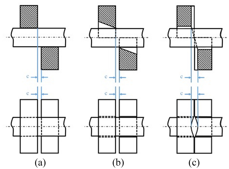
Shear clearance forms in round bar shearing process: (a) straight and parallel edged blades, (b) round and sharp edged blades, and (c) round blades with grinding relief. 30
The choice of blades’ geometry depends on the geometry of the sheared bar. In the case of round bars, sharp edged blades allow a better sheared surface quality and reduce the needed shear force.
Shear force
The applied mechanical force consists of shear force to cut the metal and friction force between the tool and remaining bar section. The shear force Fs can be calculated as following:

Where As is the surface of the sheared section. ks is the shear resistance of the bar material and can be calculated as 70%–80% of the tensile strength of the material (Rm). 32 It should be mentioned that the form of the force-displacement curve is related to the shape of the sheared surface. 33
Observations of the loading curve of shearing were carried out in several studies (Figure 3). In this figure, the different shearing steps and the respective blade/billet positions are shown. Four stages can be highlighted when friction forces are neglected: elastic deformation (AB), plastic deformation with hardening (BC), plastic deformation with cross section reduction (CD), fracture initiation, and crack propagation (DE).
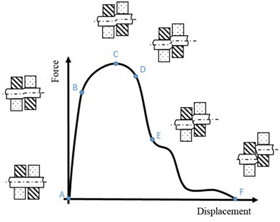
Phases of the force-displacement curve of shearing.
The fifth stage of the loading curve is where induced friction between the moving blade and the remaining fixed bar section does not allow the shear force to fall. 33
Shear rate
Shear rate (v) is defined as the speed of the press ram that pushes the moving blade. It has a direct influence on the quality of the shear surface. Many authors have tested the impact of the increase of shear rate 34 and in our studies, we obtain a better quality of the shear surface until a rate of 3–4 m/s. 30 For higher shear rates up to 10 m/s, the phenomenon of adiabatic shearing is observable. The high plastic deformation rate in the shear zone induces local heating and consequently material softening or resolution in this region. This technique of adiabatic shearing allows a high production rate, a better precision of the weight and geometry of sheared billets as well as a flat shear surface with homogenous hardness. 34 Using a small shear rate causes plastic deformation propagation to a greater extent of material (Figure 4).
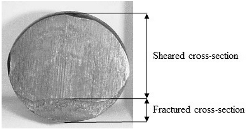
Zones of the shear surface. 32
Bar holder force
Applying a perpendicular force on the bar holder increases the formability of the material in the shear zone. 30 This fact has more importance for the shearing of non-ferrous metals and ductile steel. It was demonstrated that the increase of both the length to diameter ratio and the bar holder force have a positive effect on the precision of the billet diameter.
Blade geometry
Cutting blades can be open or closed. The geometry of open blade is defined through three angles (Figure 5).
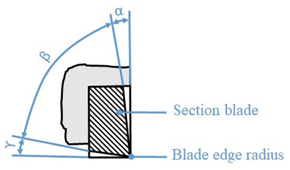
Geometry of the shear blade.
- α is the clearance angle, it reduces friction between blades and sectioned bar. The increase of this angle allows the reduction of the needed shear force but induces an increase in the burr length.
- β is the wedge angle, that must be great to ensure the stability of the blades during shearing.
- γ is the rake angle, it allows reduced heating during shearing and preserves blade life, but it should be kept low for a better shear quality.
These angles are related with the following equation:

The closed blade type allows a better shear quality, does not need a section holder, but is more expensive. The sharpness of the blades is also a geometrical measure that has a direct influence on the quality of the shear surface. This parameter is measured with the edge radius of the blade. It is known that dull blades induce ragged edges.
Shear quality
The quality of sheared billets is generally related to the geometry of the billets and in some special cases to the microstructural changes in the bar material. To use sheared billets in precision forming processes, such as precision forging and flashless forging, the weight variation should not exceed 0.5%. Inclination angle and shear surface quality are dependent on stress state in the shear zone. Depending on bar material, stress state in the shear zone has to be adjusted with the bar fixture, tool geometry and clearance in order to have a good shear quality.
Behrens et al. 25 have summarized eight geometrical defects that occur during round bar shearing, and ordered them in decreasing order of appearance. These are: unevenness of the shear plane, angle of inclination, distortion, pressure zone deformation, cut/crack ratio, earing, tongue, and fracture. Lange and Liewald 30 have cited a more exhaustive list of 17 shearing defects including burr formation.
This study focuses on four geometrical defects that are presented in Table 2 and the respective influential shear parameters.
Shearing defects and causes.
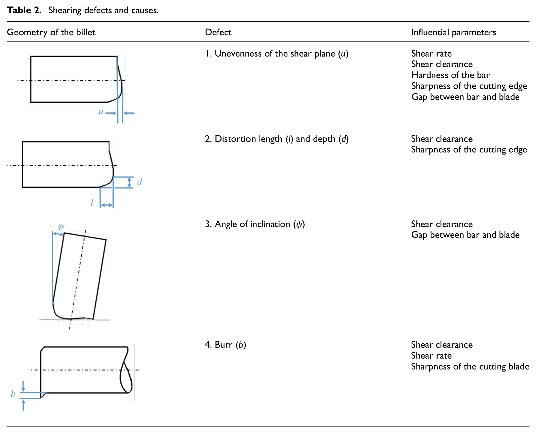
According to Table 2, the most influential parameters are shear rate and shear clearance. Besides geometrical defects, adiabatic heating can engender microstructural change on the shear surface inducing an inhomogeneous hardness distribution along the surface. When there are defects in the shear surface, a reworking process like end-face grinding is necessary and additional costs would be inevitable. In order to minimize redundant production costs, the FE analysis of the influence of the different shear parameters on the shear quality is fundamental.
Numerical study
Material behavior
Material behavior consists of elastic, plastic and fractural behavior, as summarized in Figure 6.
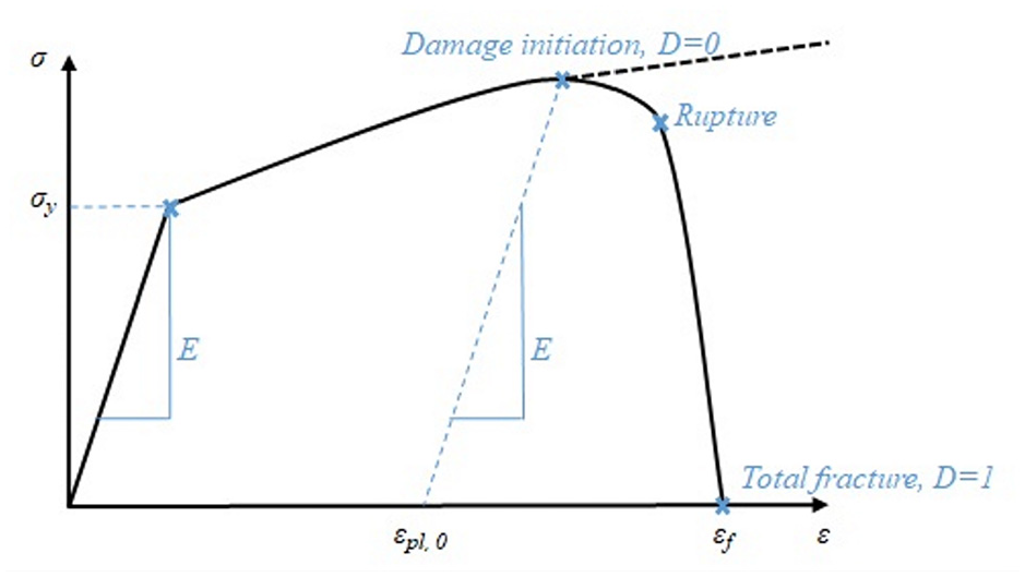
Metals plasticity and damage modeling illustration.
Accurate simulation of metal working processes requires an appropriate plasticity and failure model. Johnson-Cook models are suitable for processes with high deformation, elevated deformation speed, and high temperature variation.
The Johnson-Cook plasticity model gives the shape of the flow curve until damage initiation and its extrapolation drawn with dotted line in Figure 6. This model is based on the “J2 plasticity,” that means flow surface is independent from pressure and the third stress invariant. The equivalent plastic flow stress (σeq) is decomposed into three parts (equation (20)): strain hardening, kinematic hardening and thermal softening at elevated temperature.

Where
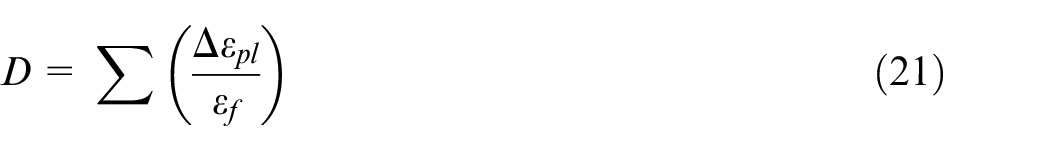
The idea of the Johnson-Cook fracture model is to express the fracture equivalent plastic strain (
According to Moakhar et al., 26 the triaxiality is an important stress state indicator that has to be considered in material modeling in shearing simulation. The authors have proven the existence of a large range of triaxiality values in the shear zone during deformation, indicating various stress states from compressive to shear and tensile states.
The first term of equation (22) describes the impact of the stress state, which is represented by the triaxiality, on the failure strain. The origin of this formulation is the work of Hancock and Mackenzie. 35 The second term takes the influence of strain rate on the deformation into consideration and the third term represents the impact of heating on the strain at fracture.
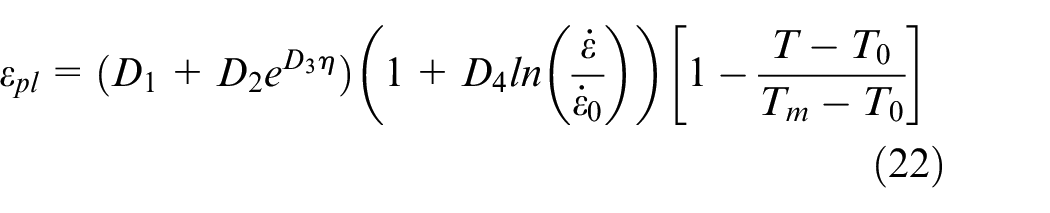
The aluminum alloy Al7075-T6 was studied. The material had undergone heat-treatment and was artificially aged. It has a high strength to weight ratio and is thus often utilized in aircraft manufacturing. 36 Some mechanical and thermal properties of the Al7075-T6 alloy are listed in Table 3.
Properties of the Al7075-T6 alloy.
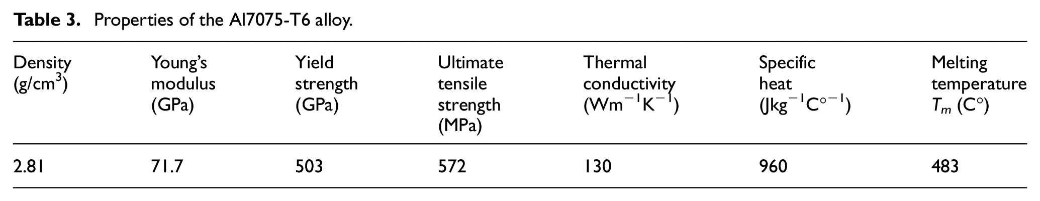
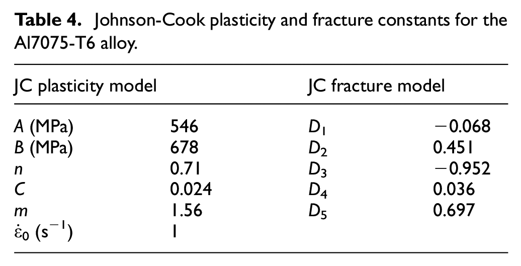
Material constants of the Johnson-Cook equations were already calibrated by Brar et al. 37 These are presented in Table 4. Plasticity constants (A, B, n, C, and m) were determined from high strain rate tension tests. Fracture constants (D1–D5) were calculated from quasi-static and medium strain rate tension tests on smooth and notched bars. The tests were conducted at room and high temperatures of up to 250°C and at strain rates in the range from 10−3 to approximately 103.
Johnson-Cook plasticity and fracture constants for the Al7075-T6 alloy.
The plasticity and ductile fracture models described above were implemented in ABAQUS/Explicit via the material description tab.
Shearing simulation
Shearing model
Figure 7 shows the shearing model as well as the studied parameters: shear rate (varied from 10−1 to 10,000−1 mm/s) and shear clearance (0.05, 0.5, 1, and 2 mm). Three rigid tools were modeled: section blade, bar holder, and bar blade. The section blade is closed and straight edged.
Shearing model.
Meshing
Thermo-mechanical modeling was conducted using thermally coupled hexahedral elements with trilinear displacement and temperature (C3D8T). Fine meshing was applied in the shear zone with a mesh size of 0.2 mm. Element deletion option was activated to permit the suppression of elements having critical damage variable values and consequently to permit the fracture. While element number is relatively elevated (more than 55,000), the mass scaling option was utilized to speed up the calculations.
Numerical results
Effect of varying clearance and shear rate on sheared billet temperature
The different geometries of the resultant shear surface as well as the temperature distribution profiles provided by FEA for different shear rates and clearances were plotted in Figures 8 to 11.
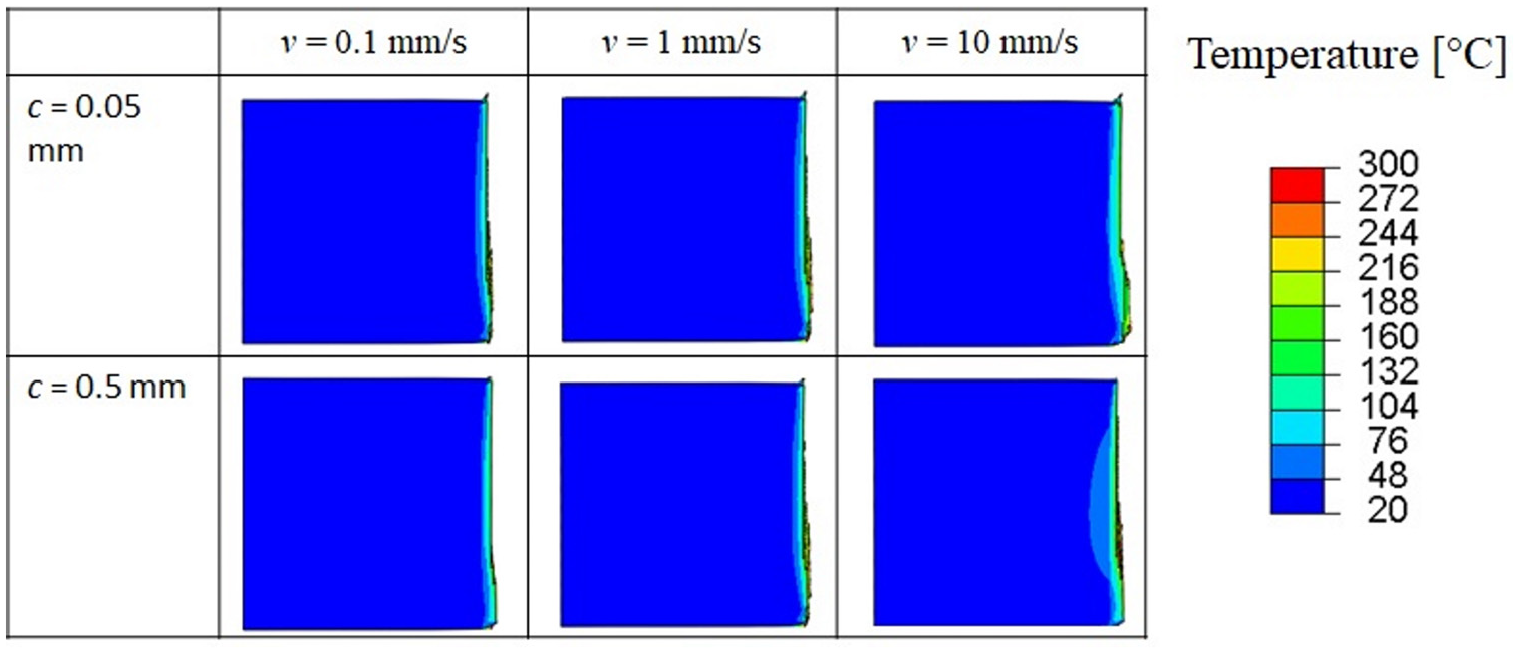
Geometry and temperature profile of sheared billets by low clearance and low shear rate.
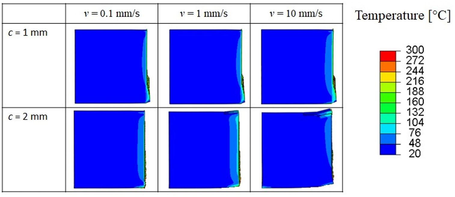
Geometry and temperature profile of sheared billets by high clearance and low shear rate.
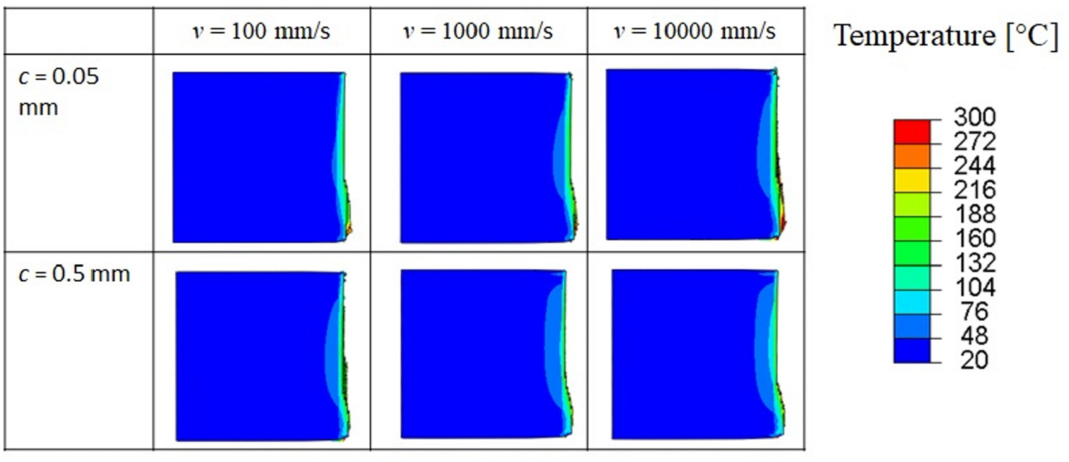
Geometry and temperature profile of sheared billets by low clearance and high shear rate.
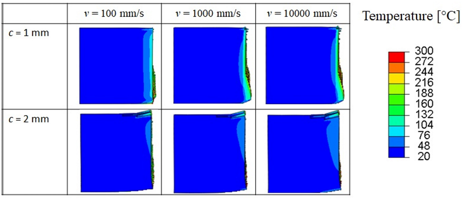
Geometry and temperature profile of sheared billets by high clearance and high shear rate.
The shear surface can clearly be divided into sheared and fractured zones. However, the height of each zone varies with the chosen shear parameters. We can easily see that the combination of high clearance and high shear rate induces a larger fractured zone on the sheared surface. With increasing shear rate, the temperature rise affects a larger material volume.
In order to clearly perceive the adiabatic effect, the maximal temperatures of all of the simulations were drawn in Figure 12. Elevated clearance induces more friction energy and elevated shear rate induces more kinetic energy. Both of these energies are transformed into heat energy. Consequently, the curve of Figure 12 shows its maximum for high clearance and shear rate. When the shear rate exceeds 10 mm/s, some elements are heated above the melting temperature (483°C). This effect is generally undesirable in real shearing.
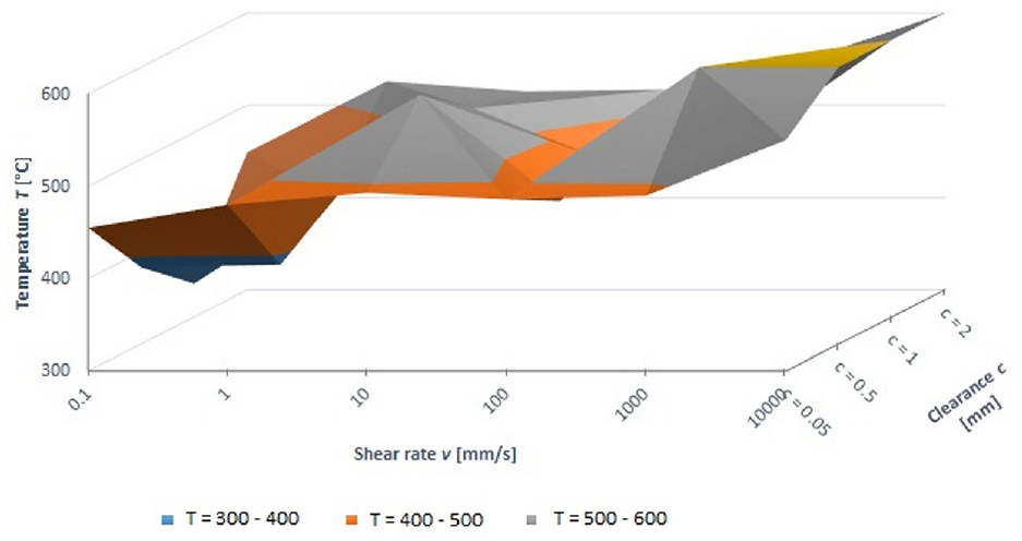
Maximal calculated temperature as function of clearance and shear rate.
Effect of varying clearance and shear rate on sheared surface geometry
The effect of varying shear clearance and shear rate on the geometry of both shear surfaces was investigated. The considered measures of the quality of sheared surface on the side of the billet are related with defects 1 and 2 in Table 2 (Figure 13). Defects 1 and 2 are the main causes of defect 3. The latter is unwanted, especially when the billet is vertically positioned in a forging process.
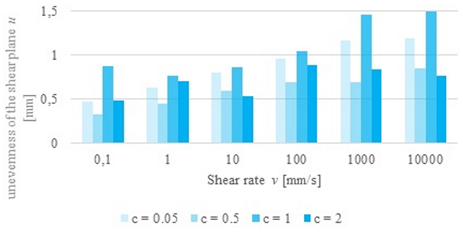
Effect of clearance and shear rate on the unevenness of the shear plane.
The unevenness of shear plane u increases with increasing shear rate. However, there is no significant difference between the results of shear rates 1000 and 10,000 mm/s. The minimal values of u were obtained when clearance c = 0.5 mm (Figure 14).
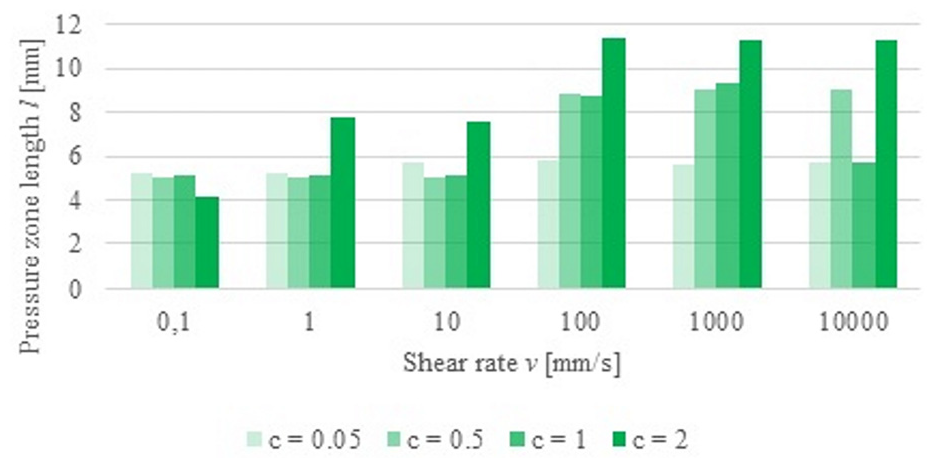
Effect of clearance and shear rate on the pressure zone length.
The pressure zone length l tends to increase with increasing shear rate until v = 100 mm/s. When the clearance is too small (c = 0.05 mm), the shear rate has no influence on the pressure zone length l (Figure 15).
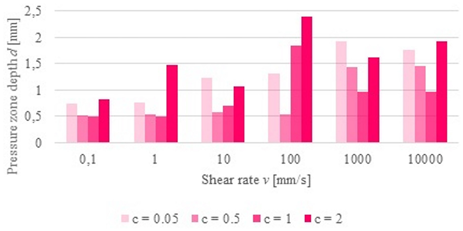
Effect of clearance and shear rate on the pressure zone depth.
The effect of the shear rate on the pressure depth d is very dependent on the clearance. For clearance c = 0.05 mm, d increases with increasing v. For clearance c = 0.5 mm, d increases from v = 1000 mm/s. For clearance c = 1 mm, d increases from v = 100 mm/s. For clearance c = 2 mm, the influence of v on d is irregular.
The most obvious defect on the side of the bar rest is burr formation (defect 4, Table 2). The influence of c and v on b is obvious (Figure 16). The burr width b increases when c and v increase.
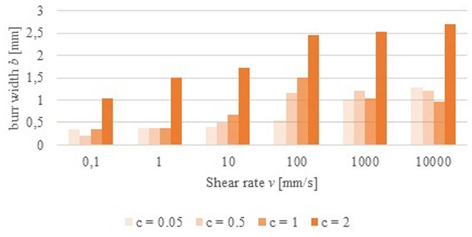
Effect of clearance and shear rate on the burr formation.
The minimal values of b were obtained by small shear rate and small clearance. The minimal values of u, l, and d were obtained with the clearances 0.5, 0.05, and 1, respectively. We conclude that the influence of the shear rate on the geometry of the shear surface depends on the clearance.
Effect of clearance and shear rate on shear force
As explained in section 3.2 there is a correlation between the phases of the force-displacement curve and the form of the sheared surface. Figure 17 shows the effect of clearance on the shape of the force-displacement curve. The elastic deformation is larger for high shear rates because of the thermal softening due to adiabatic phenomena. In the case of high clearance and high shear rate, the plastic deformation phase is larger. In this case two cracks are built in the shear zone and do not run toward each other. For the small clearances 0.05 and 0.5 mm, the shear force decreases rapidly. For large clearances, the formed burr induces notable friction so that the needed shear force remains high even after fracture initiation and crack propagation.
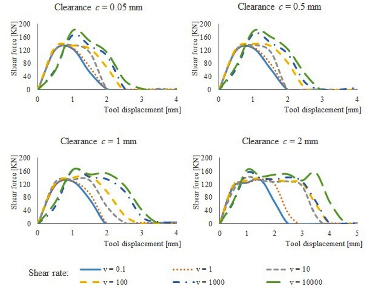
Influence of clearance and shear rate on the force-displacement curve.
Discussion
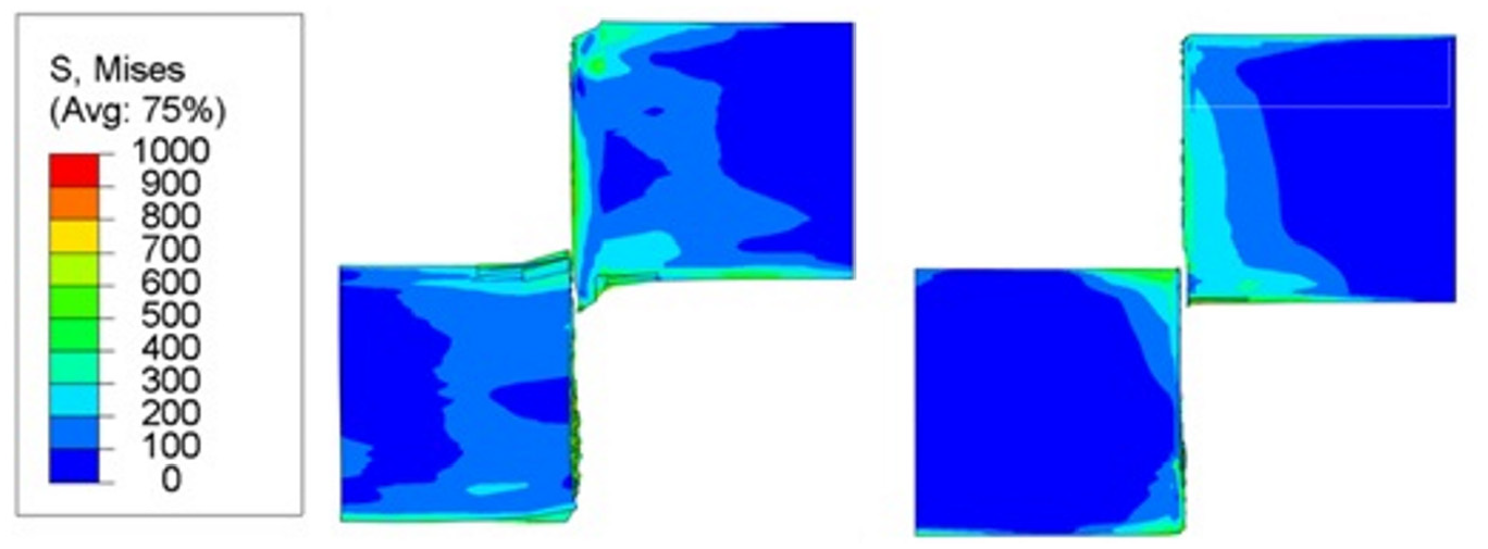
In this section, extreme cases are illustrated. Figure 16 shows the cases of maximal and minimal shear surface unevenness (u). The tool movement is in the y-direction (Figure 18).
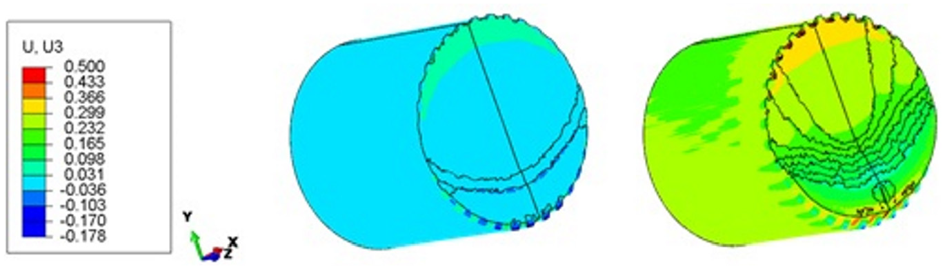
Displacement in the z-direction on the shear surface in the cases of c = 0.5 mm, v = 0.1 mm/s (left) and c = 1 mm, v = 10,000 mm/s (right).
Figure 19 shows the cases with maximal and minimal burr. We notice that even if u, l, and d were reduced to a shear rate of 10,000 mm/s, a larger burr is formed in the rest bar. Moreover, the results suggest that smaller clearance causes smaller fractured zone height. Contrary to the expectations about the quality of high-speed adiabatic shearing, we conclude that in the case of the AL7075-T6 bars, high shear rates increase the unevenness und burr on the sheared surface and cause material heating over melting temperature in critical points. For this reason, it is necessary to conduct a numerical parametric study to search the best parameter combination for each sheared material, depending on the precision requirements of the subsequent billet employment. The shear parameters may also include material heating, sharpness of the cutting edge and gap between bar and blade.
Burr formation in the cases of maximal burr (left: c = 2 mm and v = 10,000 mm/s) and minimal burr (right: c = 0.5 mm and v = 0.1 mm/s).
Conclusion
This study applied the finite element method (FEM) to determine the influence of the most relevant shear parameters on the quality of shearing of aluminum bars. A strong thermo-mechanical coupling was necessary to account for the interactions between the mechanical material properties and the temperature evolution. This was realized through the use of plasticity and fracture models of Johnson-Cook as well as C3D8T elements in the FEM model of the bar. A series of three-dimensional numerical simulations have been carried out with shear rates from 10−1 to 104 mm/s and shear clearances from 0.5 to 2 mm. As a result, we can conclude that the best shear surface quality for the aluminum alloy AL7075-T6 was observed in the case of clearance 0.5 mm and shear rate 0.1 mm/s. High shear rates induce the spread of the adiabatic effect on a larger material volume and increase the unevenness of the shear plane and the burr width. The described method can be useful to parametrize shearing process depending on material properties of the sheared bar.
Footnotes
Declaration of conflicting interests
The author(s) declared no potential conflicts of interest with respect to the research, authorship, and/or publication of this article.
Funding
The author(s) received no financial support for the research, authorship, and/or publication of this article.