
Abstract
Additive manufacturing has been proven to be a promising technology for fabricating high-performance dies, molds, and conformal cooling channels. As one of the manufacturing methods, wire and arc additive manufacturing displays unique advantages of low cost and high deposition rate that are better than other high energy beam-based ones. This paper presents a preliminary study of fabricating integrated cooling channels by CMT-based wire and arc additive manufacturing process. The deposition strategies for fabricating circular cross-sectional cooling channels both in conformal and straight-line patterns have been investigated. It included optimizing the welding torch angle, fabricating the enclosed semicircle structure and predicting the collision between the torch and constructed part. The cooling effect test was also conducted on both the conformal cooling channel and straight-line cooling channel. The results affirmed a higher cooling efficiency and better uniform cooling effect of the conformal cooling channel than straight-line cooling channel.
Keywords
Introduction
Injection molding is a commonly applied process for manufacturing varieties of plastic parts by melting thermoplastic and thermosetting materials. 1 Filling and packing stage, cooling stage, and ejection stage are the three main stages during the injection molding process. 2 Among them, cooling stage takes more than two thirds of the total processing time and highly affects the final molding quality. Thermal energy must be taken away from the molds rapidly and efficiently by continuously flowing coolant to achieve high production efficiency and short exposure time at high temperature for the molds.3,4 A suitable design of the cooling system is crucial to obtain quality parts. 5
Usually, the cooling channels are manufactured by traditional machining methods such as drilling. This method can only produce straight line cooling channels (SLCC) which often cause uneven cooling, long cycle time, warpage, and other issues. 6 Compared to SLCC, conformal cooling channels (CCC) have the same distance between the channels and components, leading to a rapid and uniform cooling effect on the molds. 7 However, their manufacturing can be challenged for traditional processing techniques. 8 The appearance of additive manufacturing (AM) methods allow CCC’s overall design for dies and molds. So far, most attention focus on high energy beam-based AM, for example, selective laser sinter (SLS) and direct metal laser sintering (DMLS). 9 Even though many kinds of literatures about additive manufactured products can be found, they are mainly focusing on materials, microstructure, and mechanical properties, reviews about additive manufactured molds or dies with internal fluid channels are still very rare.10,11 Cortina et al. 12 manufactured bimetallic hot stamping tools by laser-based directed energy deposition (DED). An AISI 1045 core with 1 mm thickness of H13 coating was obtained and tested for mechanical and metallographic analysis. The results showed that the laser deposited H13 presented similar characteristics to those of cast H13 steel. For their studied geometry, the additive manufactured part can reduce the cycle time by 44.5% compared to the cast one. However, their thermal results were only evaluated by thermal simulation instead of experimental tests. Tan et al. 13 designed and manufactured a new injection mold with conformal cooling channels by laser powder bed fusion. The diameters of the cooling channels manufactured by supportless and self-supporting methods can reach 10 mm and 20 mm, respectively. The mold flow results demonstrated that the injection mold with self-supported channels of 13 mm in diameter could reduce the cooling time by more than 20% compared to 8 mm normal-sized channel.
The significant advantages of high energy beam-based AM can offer are the cleaner and environmentally friendlier operation and the ability to manufacture complex structured products. 14 Nevertheless, they are much more expensive than traditional machining methods due to their high initial investment, specialized maintenance, and substantial amount of materials cost, which highly limited their practical applications. 15 The relatively low deposition rate is also a serious shortcoming for manufacturing large-scale components.
Arc discharge is another well-known heat resource for additive manufacturing, which can build geometrical features through metal welds deposition. 16 Compared with other high energy beam-based AM, this technique owns the virtues of high deposition efficiency, low manufacturing cost, and ample materials supplies. 17 On the other hand, the disadvantages of low forming accuracy, high residual stress, and deformation are more intractable and made this technology farther away from practical applications. 18 Fortunately, the rough surface of the cooling channels made by WAAM can be benefit for increasing the total contact area with the coolant and obtaining a better cooling efficiency.
Up to now, a state-of-the-art review of injection molds or stamping dies manufactured by WAAM process is still absent, not to mention the ones with self-supported cooling channels. 19 Most studies are mainly about establishing the relationship between processing parameters and dimension of as-built objects, investigating the microstructures and mechanical properties, and the deposition ability of different materials. H13 steel is one of the most popular die materials for casting metal parts and widely studied both by high energy beam-based AM and WAAM. Wang et al. 20 have fabricated a thin-walled part by H13 wires using MIG-based WAAM process. The microstructures and mechanical properties before and after heat treatment have been characterized. Ge et al. 21 has developed some preliminary studies about the probability of producing near-net-shape H13 die by CMT-based WAAM process. The internal 3D pore distribution, microstructures, and mechanical properties of deposited H13 blocks have been investigated. Suarez et al. 22 deposited simple and multi-pass structures of P20 steel using TIG based WAAM process. Bead geometry, hardness distribution, microstructure, and quality features after grinding, polishing, and texturing have all been studied. The mutual heat effect of multi-pass welding has also been studied. Tanvir et al. 23 investigated the microstructure, tensile properties, and microhardness of wire and arc additive manufactured H13 tool steel. Although pores and voids were present in the as-built objects, the tensile strength is still comparable to other AM methods. Ali et al. 24 studied the influence of arc energy and thermal field on the mechanical properties and microstructure of the manufactured hot work steel X37CrMoV 5-1 by CMT-based WAAM process, which is commonly used material for manufacturing of plastic molds, hot extrusion dies and forging dies. So far, no research about fabricating cooling channels by wire and arc-based additive manufacturing processes has been found.
This research attempted to manufacture the integrated circular cooling channels by CMT-based WAAM process. Considering a situation that the turntable is absent, or the substrate need to be manufactured with cooling channels is hard to be manipulate by a turntable, in this case, a good control of the welding torch posture is the only solution to finish the work. So the study present here is mainly focus on manufacturing cooling channels by means of varied welding torch position.
Experimental details
Experimental setup
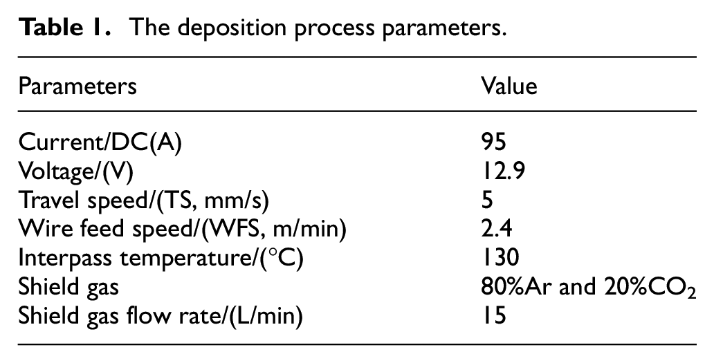
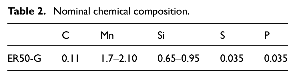
The schematic diagram of CMT-based WAAM system has been shown in Figure 1. This configuration consists of a Cold Metal Transfer welding facility and a six-axis ABB robot. Low-carbon steel (Q235) plates, with dimension of 200 mm × 200 mm × 5 mm, were used as single use substrates and were screwed to a water-cooled aluminum cooling substrate. This setup was intended to achieve a faster cooling rate than using the Q235 plate as the substrate only. The welding parameters are listed in Table 1. ER50-G filler wire of 1.2 mm in diameter was used as deposition material. The nominal chemical composition was listed in Table 2.
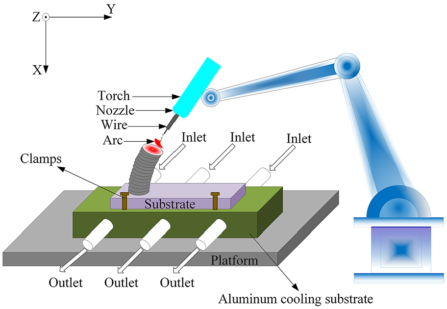
Schematic drawing of depositing setup.
The deposition process parameters.
Nominal chemical composition.
For fabricating structures by robot-controlled WAAM process, a three-dimensional model file containing the geometrical features and layer dimensional information of the preprocessing structure was used as an input data and put into a CAD/CAM software called MasterCAM. The welding torch location and tool path were then generated and output directly into an industrial robot programming software (Robotmaster) to control the welding torch posture. The flowchart for the robot control program is shown in Figure 2.
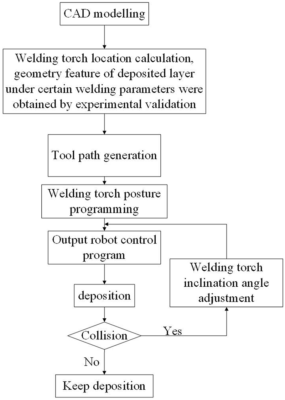
The management and controlling of the CMT-based WAAM process.
Design and build of cooling channels
As a preliminary study, only part of a core mold has been fabricated rather than making the whole mold. The plastic component is produced between the cavity and the core mold. Two kinds of cooling channel patterns (CCC and SLCC) have been suggested, as shown in Figure 3, and their geometry features can be seen in Figures 4 and 5.
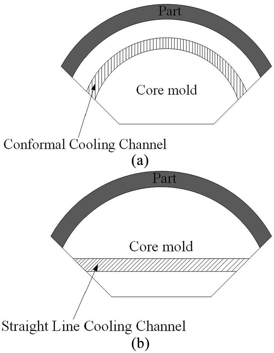
Two kinds of cooling channel designs: (a) CCC and (b) SLCC.
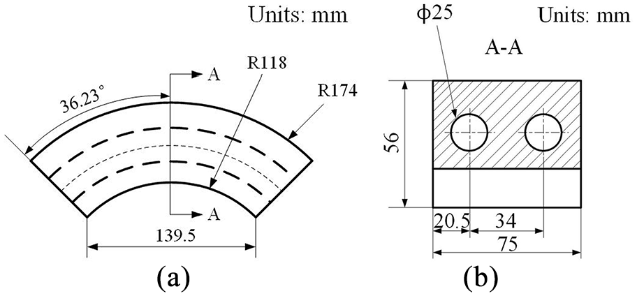
The geometry of CCC defined in the CAD model: (a) front view and (b) section view.
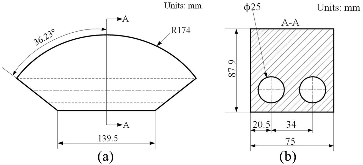
The geometry of SLCC defined in the CAD model: (a) front view and (b) section view.
The core mold and its cooling channels were fabricated without using any turntable, and this process was illustrated in Figure 6. The building of core mold by WAAM process can be partitioned into three steps: first, the bottom concave part was deposited directly on the substrate, then the enclosed semicircle arch structure on top of the concave part to form the passage of coolant. The enclosed circular shape was constructed by depositing two quartered arch structures alternately layer by layer; at last, fill up the areas outside the cooling channels by a stack of welding layers. In order to improve the production efficiency, the deposition of conformal cooling channels was conducted on a curved substrate. The full cooling channel path planning was demonstrated in Figure 7. The green lines, blue lines, and red lines depict the path planning for the concave part, semicircle arch part and the part outside the cooling channel, respectively.
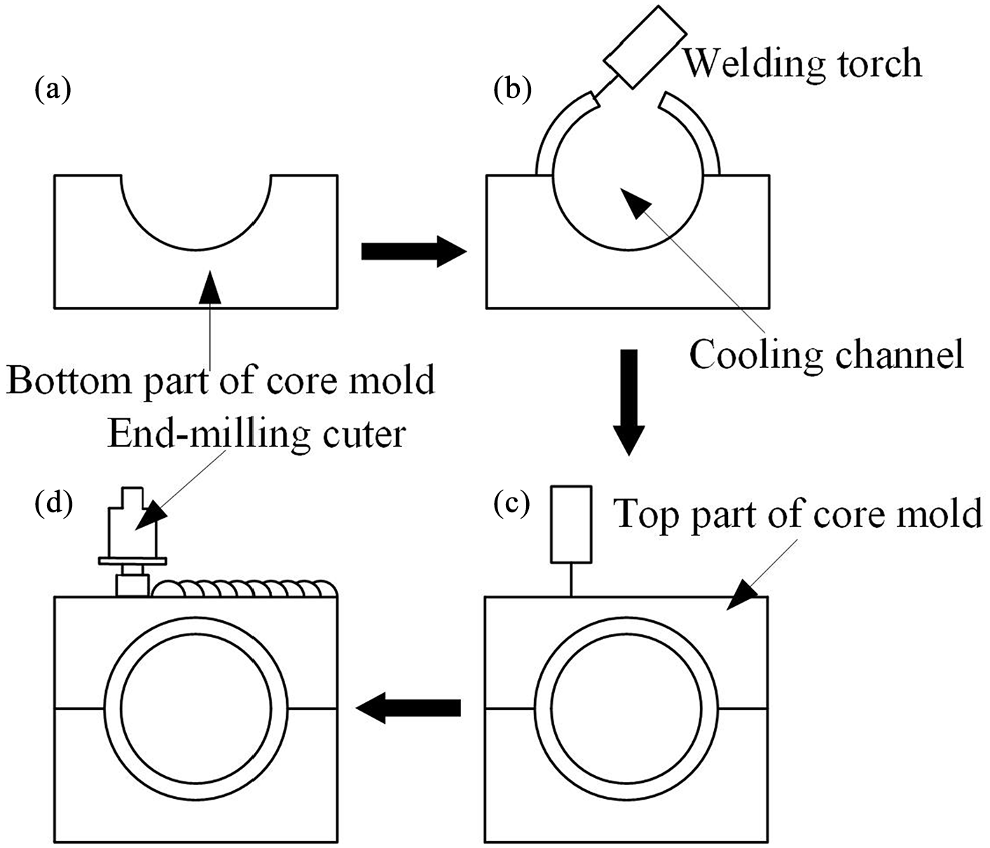
Schematic representation of building cooling channels on a curved substrate without any turntable: (a) deposition of the bottom part of the core mold, (b) deposition of the cooling channel, (c) deposition of the top part of the core mold, and (d) surface finishing of the top surface.
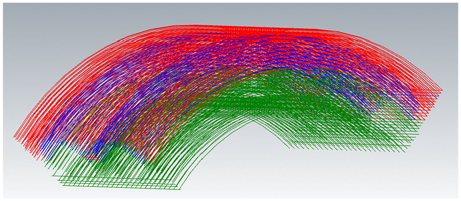
Tool path planning for building CCC on a curved substrate.
Definition of the circular cross-sectional cooling channel
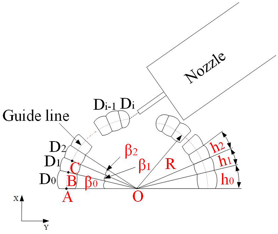
As mentioned in section 2.2, the cooling channel is a hollow circular structure formed by a concave in the bottom and two quartered arch structures at the top. This section is focused on fabricating the two quartered arch structures. Before discussing the building process, some critical parameters were introduced here. For an inclined or overhanging structure, as shown in Figure 8, the first layer is deposited directly on the substrate, and its molten pool is horizontal without any inclination. But from the second layer, the pending molten pool may overflow due to the gravity and result in a lower layer height than the first one. For simplifying the expression, we defined the height of the first layer as h0 and the height from the second layer to the last as h1 (assumed that the layer height difference from the second layer and above are minimal), as illustrated in Figure 8.
Schematic view of defined layer height and included angle.
The angle between line AO and line BO is β0. Point A is the intersection point between the bottom surface of the first layer and the guideline. Point O is the center of the guide line. Point B is the intersection point between the upper surface of the first layer and the guideline and point C is the intersection point between the upper surface of the second layer and the guideline. The angle between line BO and line CO is β1. Since we assumed that the layer heights keep stable from the second layer and above, then the included angles from the second layer are considered constant, then β0 and β1 can be formulated as:


Where R is the radius of the cooling channel.
The deposition layer number n for a quartered arch structure with a specific radius R can be roughly calculated by the arc length of the quartered arch structure and layer heights, namely, use the sum of the layer height to approximate the arc length s, then the layer number n can be calculated as the following equation:

For example, for depositing a quartered arch structure with radius R of 20 mm, a quarter of the circumference, that is, the arc length s is 2πR/4 = 31.4 mm. The weld bead obtained by the welding parameters listed in Table 2 has an average bead width of 4.6 mm, the height of the first layer h0 = 2.04 mm, and the height of the second layer h1 = 1.51 mm. Then according to equation (3), the deposition layer number n is about 20. From Figure 8, it can be known that, for a cooling channel with a radius R of 20 mm, a weld bead width of 4.6 mm, then the inner and outer radius of the cooling channel are around 17 mm and 22 mm, respectively.
Cooling experiment
Two core molds with different circular cooling channels patterns were built and performed for the cooling experiment: one mold was made with CCC, and another one is with SLCC. Their geometries were shown in Figures 4 and 5. A dozen K-type thermocouples were placed in three lines (vertical to the cooling channels) on the upper surface of the core mold, each line has four thermocouples, and their relative position was revealed in Figure 9. Since this is a symmetry structure, we only set the thermocouples in the left part of the structure. Thermocouples set in line A have the same distance from the core surface to CCC and SLCC. Line C is situated on the top of the upper surface, and the thermocouples have a much smaller distance to CCC than to SLCC. Line B is located just between lines A and C, and the thermocouples placed in it have a shorter distance to CCC than to SLCC. Thermocouples set in Line 2 and Line 4 (along the cooling channel’s longitudinal direction) are directly on top of the cooling channels; on the other hand, the ones set in Line 1 and Line 3 are not. The two sides of each cooling channel were tapped and screwed to the water pipes, as shown in Figure 10. The whole structure was heated to 100°C and then cooled by flowing water with flow rates of 4 L/min, 6 L/min, 8 L/min, 10 L/min, and 12 L/min, respectively. The inlet water temperature was 25°C. The temperature was monitored by a paperless recorder system.
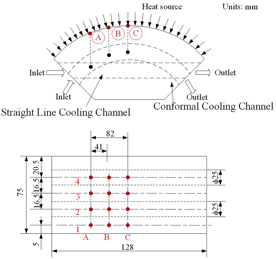
Schematic of thermal flow test apparatus.
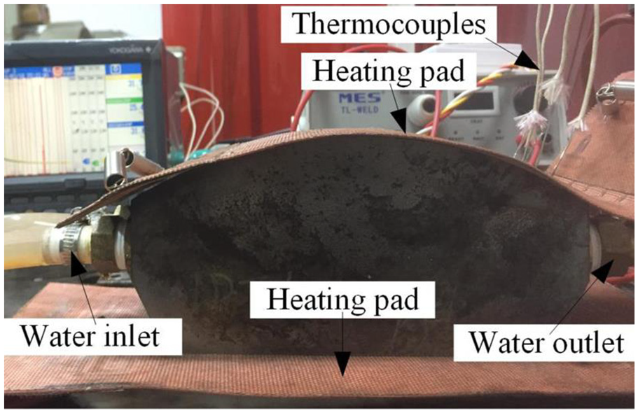
Demonstration of cooling experiment.
Results and discussion
Fabrication strategy for building quartered arch structures
Effect of the torch inclination angle
When WAAM metallic parts, if a turntable is absent, or substrate is hard to be fixed on a rotational table, inclined welding torch posture is the only solution to deposit parts with complex feature. The torch can be stayed at a constant angle or changed its angle gradually according to the shape of the structure during the building process. This section will discuss the effect of torch inclination angles on the dimensional accuracy of the as-built structures. A Creaform’s Handyscan 3D scanner is used to scan the profiles and obtained a massive bunch of cloud data. The data will be processed and translated into a 3D entity model, at last the profile data will be compared to the theoretical model. In this section, only one-quarter of the circular cooling channel with a radius R of 20 mm was experimented in order to improve the efficiency and decrease cost.
In the first case, the torch was stationary and the inclination angle was set to 35°, 40°, and 45°, respectively. Figure 11 shows the cross-sectional outlines of deposited quartered arch structures under different torch inclination angles. The yellow backgrounds represent the theoretical outline of the substrate and the quartered arch structures, and the black line is the measured outline of the deposited quartered arch structures by 3D scanner. It can be seen that all three quartered arch structures deviated from the theoretical outline.
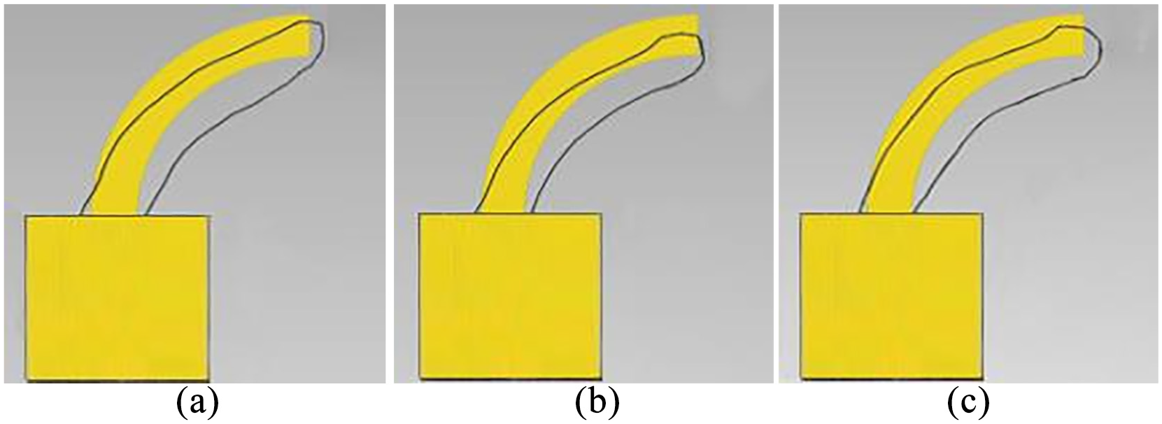
Cross-section of quartered arches fabricated by the constant torch inclination angle: (a) 35°, (b) 40°, and (c) 45°.
In the second case, keeps other parameters constant, and alters the torch inclination angle during the fabrication process. The torch was vertical to the substrate when depositing the first layer and then changed its inclination angle as the number of deposition layers increases. When deposited the second layer, the torch deflected an angle of β0, then the inclination angle

Figure 12 shows the cross-section of the quartered arch structure deposited by changing torch inclination angles. It can be seen that this outline has a good agreement with the theoretical one. The dimensional comparison is shown in Figure 13. Due to the considerable deviation between the curves built by constant torch angles and the theoretical curve, only one-eighth of their point cloud data have been processed and plotted. It can be seen that a large dimensional gap is present between the curve built by constant torch angle and the theoretical one. The maximum absolute error is as high as 3 mm. It is evident that this deposition strategy of constant torch angle cannot obtain a favorable structural appearance. On the other hand, a good agreement can be found between the curve built by varied torch angle and the theoretical one.
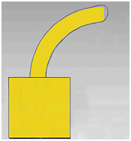
Cross-section of a quartered arch structure fabricated by the varied torch inclination angle.
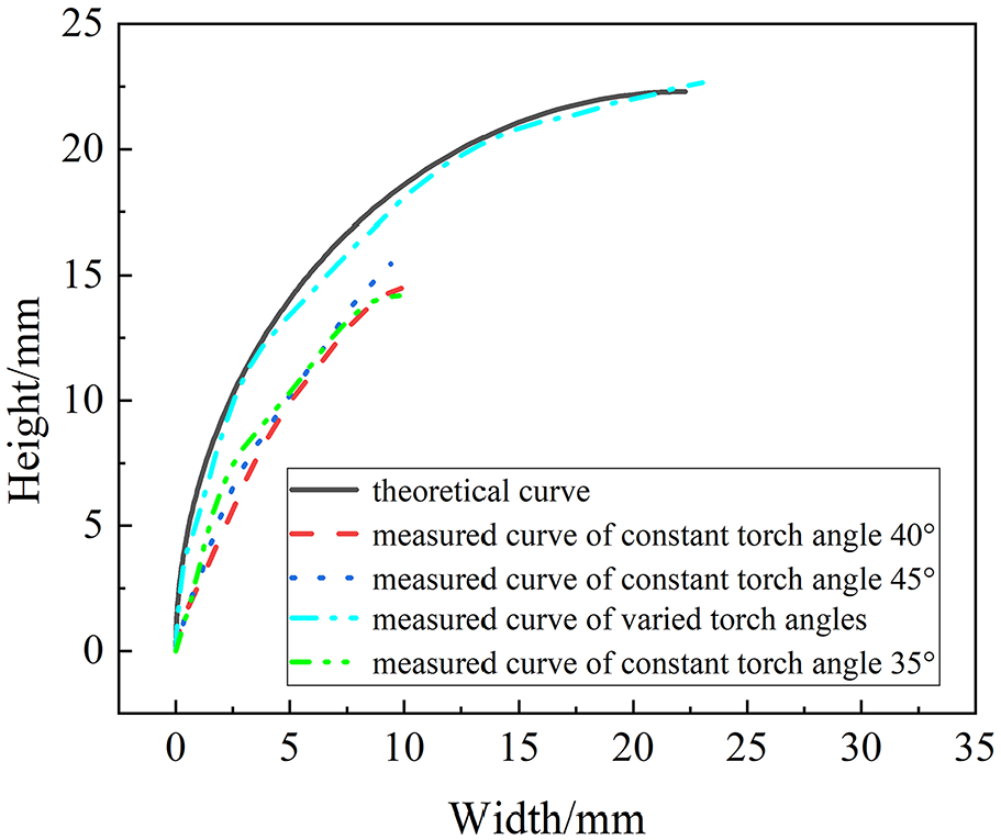
Comparison of theoretical and measured quartered arch structure outlines.
Regression analysis was used to quantify the difference between the theoretical and measured curves. The fitting degree can be expressed by the coefficient of R2, which was determined by
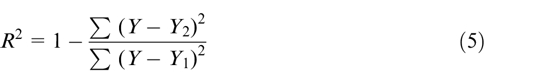
Where Y1 is the curve value measured by a 3D laser scanner, and Y2 is the value calculated from the theoretical curve of x2 + y2 = r2. The calculated R2 between curves of theoretical and varied torch angles, constant angle of 35°, 40°, and 45° are 0.9873, 0.7233, 0.6360, and 0.7707. The larger R2, the higher fitting degree to the theoretical curve.
Collision between the torch and constructed part
The enclosed semicircle structure was fabricated by connecting two quartered arch structures by one weld. The two quartered arch structures were deposited alternately by moving the welding torch from one arch to another (Figure 8). It is essential to locate the torch’s exact location after each position shift. An offline robot program (Robotmaster) was used to control the torch position.
As the deposition height increases, two quartered arch structures close to each other, the torch inclination angle
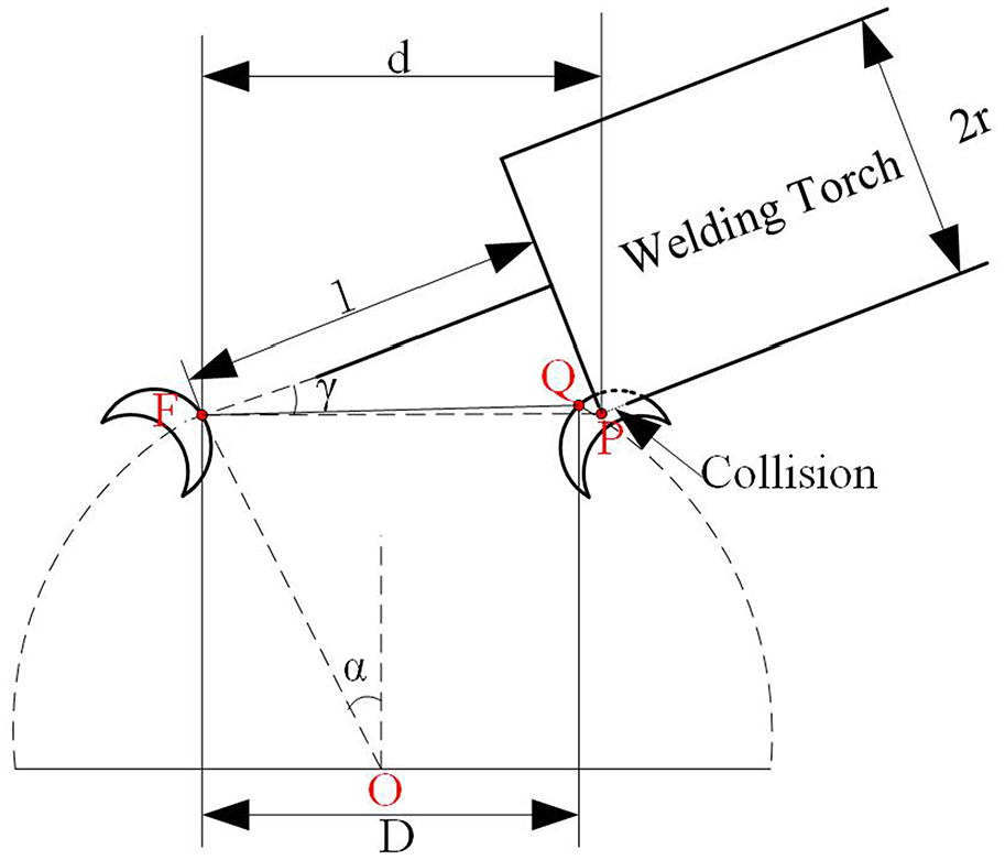
A possible collision between the torch and the fabricated structure.
The occurrence of a collision or not can be simply judged by the condition given below. Supposed that the collision happens when deposited the nth layer, then from Figure 14, we can have that:

Where D is the distance between the two quartered arches, it can be formulated as:

d is the distance between point F (the intersection between the torch center axis and the upper surface of the depositing layer) to the point P (outer rim point of the torch nozzle), and it can be expressed as:
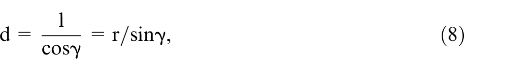
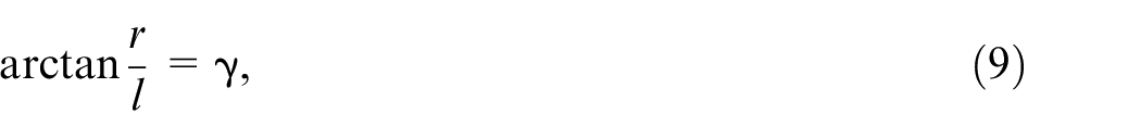
where l is the extended distance from the nozzle tip to point F; r is the torch nozzle radius; γ is the included angle between the extension of the torch center axis and line FP.
For example, when deposits the 15th layer, n = 15, β0 =
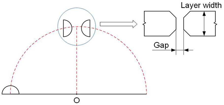
Fabrication of enclosed semicircle structure
After 20-layer deposition, two quartered arch structures were finished but with a small gap between them. That’s because the deposition layer number was just approximately calculated. Under this condition, considered the upper part of the two quartered arch structures as an X-type joint, the work of making an enclosed semicircle structure can be simplified as applying a penetration weld bead, as shown in Figure 15. An optimum gap of the X-type joint is crucial for obtaining one-side welding with back-formation. The layer width was considered as the joint thickness. The optimum gap can be acquired by a table referring to the X-type joint. If the present gap is smaller than the optimum gap, mechanical milling will be applied to increase the gap. If the gap is larger, an additional one or more layer/layers will be deposited on one or both quartered arch structures depending on the specific situation and again adjust the gap close to the optimum value by milling. In our case, the layer width is 4.6 mm, and the optimum gap is about 0.5 mm. Figure 16(a) shows the macrograph of two quartered arch structures with an optimum gap of 0.5 mm, and the enclosed circular structure after connecting them were shown in Figure 16(b) and (c).
Bridge the gap between the two quartered arch structures: (a) the gap between two quartered arch structures after 20 layers deposition, (b) top view after connecting, and(c) front view after connecting.
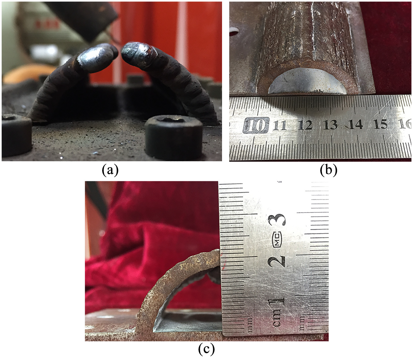
Enclosed circular structure by connecting two quartered arches with an interval distance of 0.5 mm: (a) the gap between two quartered arch structures after 20 layers deposition, (b) top view after connecting, and (c) front view after connecting.
Cooling channels formation
Figures 17 and 18 show the forming process and final appearance of WAAM manufactured core mold with CCC and SLCC, respectively. To improve the deposition efficiency, we used a curved plate as the substrate and built the cooling channels by following its curvature to obtain the so-called CCC. The SLCC was deposited on a flat substrate. During the deposition process, the welding torch angle was changed according to the layer height, and the torch inclination angle
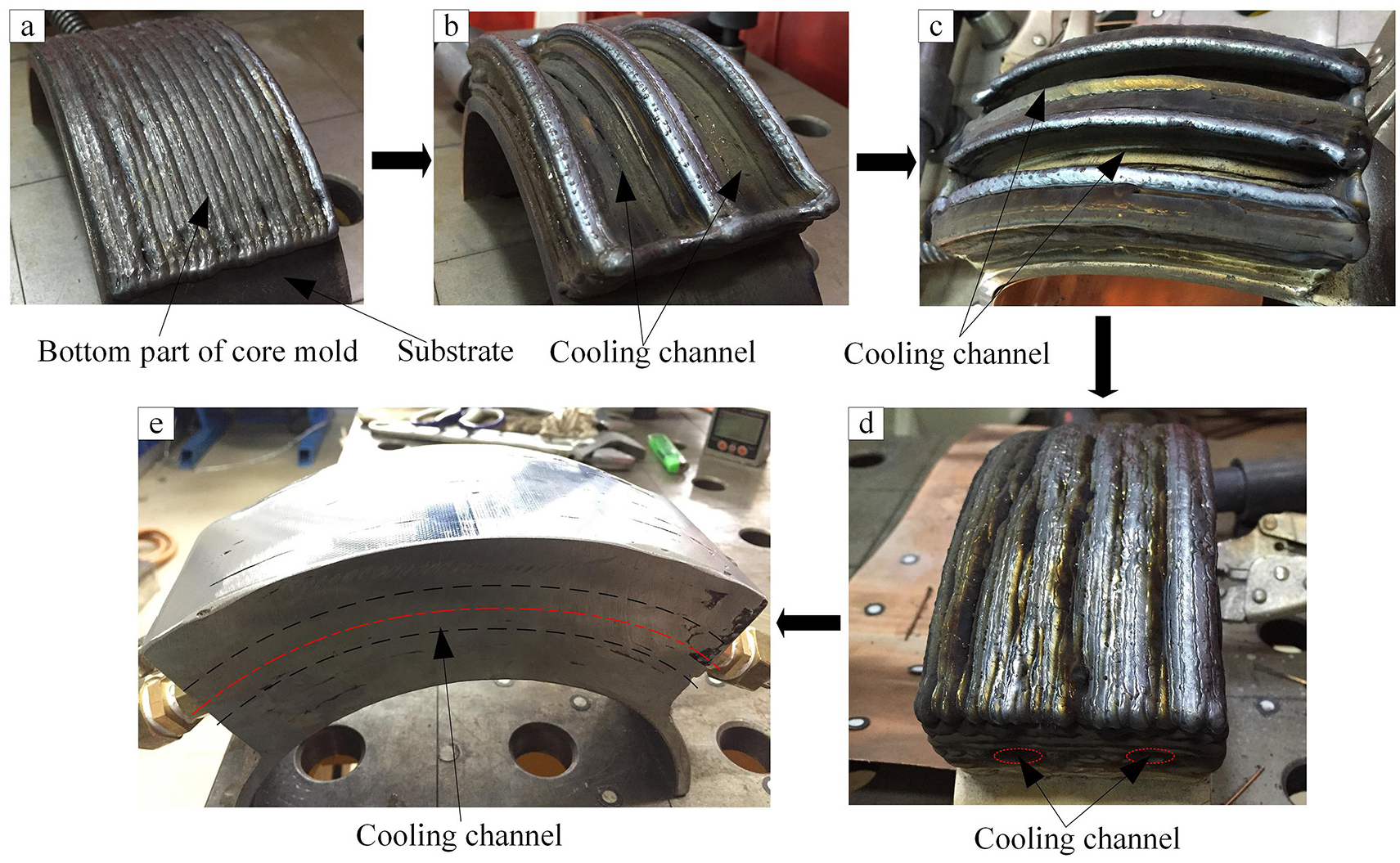
Core mold with CCC fabricated on the curved substrate by WAAM: (a) building the bottom part of the core mold, (b) building the cooling channels, (c) almost finished cooling channels, (d) finished cooling channels, and (e) finished core mold with CCC.
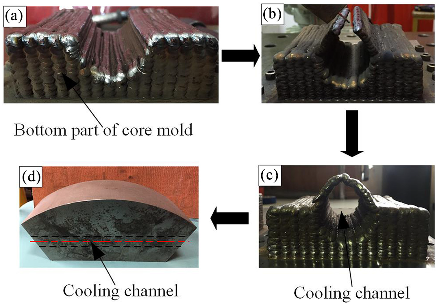
Core mold with SLCC fabricated by WAAM: (a) building of bottom part of the core mold, (b) building cooling channel, (c) finished cooling channel, and (d) finished core mold with SLCC.
Cooling effects
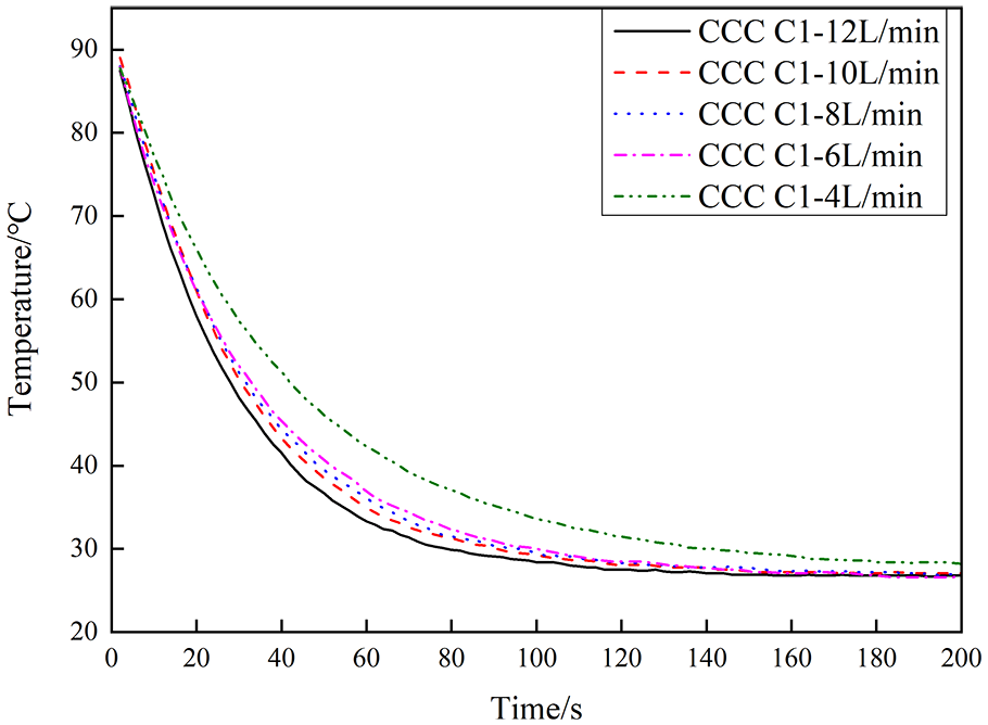
Figures 19 to 21 indicate the cooling effect of the CCC and SLCC fabricated by WAAM. Figure 19 compares the cooling curves at point C1 of the CCC under five different flowing rates. C1 means the intersection point between line C and line 1, and the position is already demonstrated in Figure 9. C2 represents the intersection point between line C and line 2, and so forth, and so on.
Cooling curves of C1 at different cooling rates.
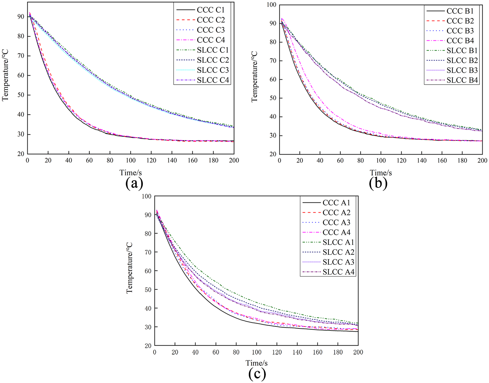
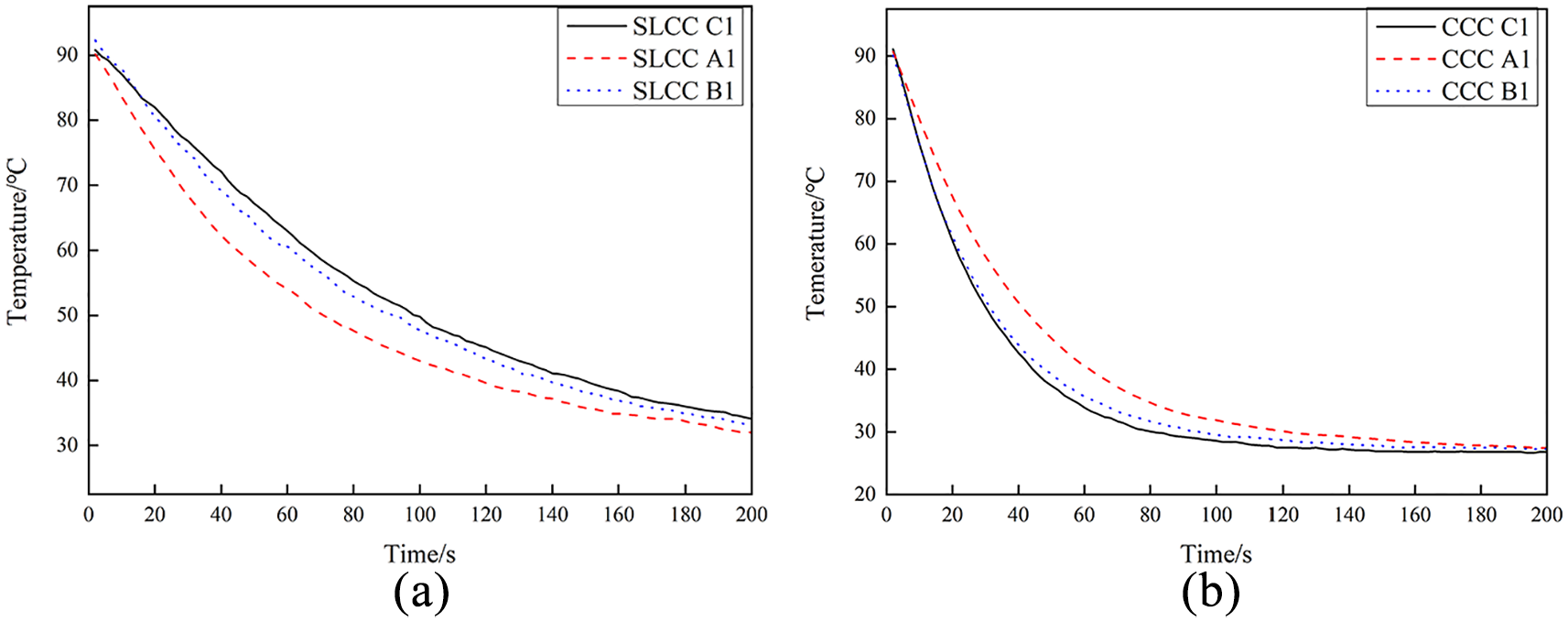
Comparison of cooling curves of SLCC and CCC at a flowing rate of 12 L/min: (a) line C, (b) line B, and (c) line A.
Cooling effects comparison between SLCC and CCC at a flowing rate of 12 L/min: (a) SLCC and (b) CCC.
According to Figure 19, as the flowing rate increases, the cooling rate increases. For example, for CCC, the cooling times from 90°C to 30°C were the 80 s and 120 s at the coolant flowing rate of 12 L/min and 4 L/min, respectively.
In Figure 20(a), the top four curves represented the Time-Temperature curves obtained by the thermocouples from C1 to C4 of CCC; the bottom four curves represented the Time-Temperature curves obtained by the thermocouples from C1 to C4 of SLCC. There is a minor difference between the four thermocouples on line C, no matter for CCC or SLCC. Their cooling times for CCC and SLCC from temperature 90°C to 30°C at a coolant flowing rate of 12 L/min were 80 s and more than 200 s, respectively. It means a substantial cooling time reduction of CCC.
But this cooling time reduction was not so evident as exhibited by the Time-Temperature curve obtained by thermocouples situated in line A (Figure 20(c)). It can be explained as the same distance between the upper surface to SLCC and to CCC. For curves shown in Figure 20(b), since thermocouples in line B had a smaller range to CCC than to SLCC, CCC’s cooling rate was still faster than that of SLCC, but not as quickly as line C.
In Figure 21(a), line A1 of SLCC showed the rapidest cooling rate which had the nearest distance to the cooling channel. Line C had the farthest distance to cooling channels, so it exhibited the slowest cooling rate compared to A1 and B1. This result testified the uneven cooling of SLCC. For CCC, as shown in Figure 21(b), the Time-Temperature curves obtained by thermocouples in different positions should present a similar cooling rate due to the uniform distance between the thermocouples to the cooling channels. However, the curve obtained by thermocouple A1 showed a slightly slower cooling rate than that of B1 and C1. The sectional micrograph of Figure 22 demonstrated that the distance between the upper surface and the cooling channels was not as uniform as designed, so did the cooling rate at different positions.
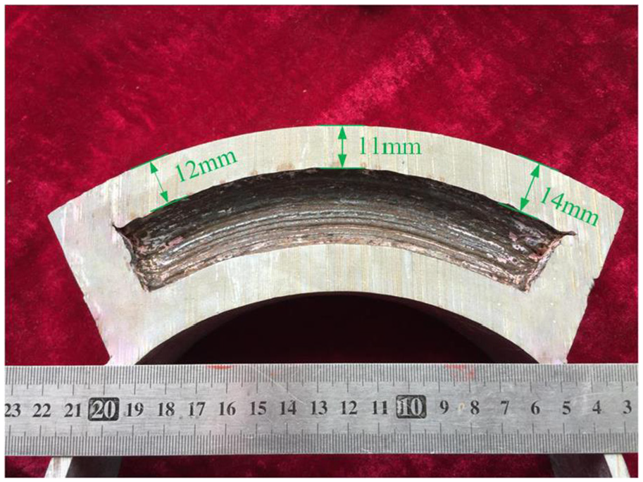
Inside inspection of CCC.
Pros and cons of the proposed method
This work has testified the possibility of manufacturing integrated cooling channels by Wire and arc additive manufacturing process and compared the cooling effect between two types of cooling channels (conformal and straight line). However, this study was not related to any mechanical property of the additive manufactured components. Residual stress certainly exists in the as-built components, but how much it can affect on the mechanical properties is not aware. Furthermore, how to eliminate the residual stress within the structure also needs to be solved. Local post-heat treatment can be one effective approach.
Conclusions and future work
Under the circumstance of positional welding, the welding torch position plays an essential role in obtaining a dimensional accuracy component. As the deposition layer number increases, the torch inclination angle changes gradually according to the curvature of the substrate instead of keeping it constant;
Collision is unavoidable between the welding torch and the constructed part. A simple mathematic model has been proposed to predict the occurrence of a collision. But a visual detection during the production process must be equipped in further research to prevent the appearance of collision completely;
An optimum gap between the two quartered arch structures is critical for obtaining a semicircle with suitable geometry. The optimum value is related to the layer width of the weld bead. The gap can be adjusted by mechanical machining;
Based on the strategies of depositing quartered arch structures and semicircular geometry features, circular cross-sectional cooling channels both in the conformal cooling channel and straight-line cooling channel pattern have been successfully fabricated by using CMT-based WAAM;
Water cooling experiment results showed the real cooling time from 90°C to 30°C at a coolant flow rate of 12 L/min was 80 s and more than 200 s by conformal cooling channel and straight-line cooling channel, respectively. Thermocouples placed in the same longitudinal line displayed similar Time-Temperature curves, which indicates a better uniform cooling for both conformal cooling channel and straight-line cooling channel. However, the dimensional difference between thermocouple and cooling channel can bring small fluctuate in cooling effect.
Future work on this topic will focus on fabricating conformal cooling channels on realistic injection mold. The injection molding experiment of producing plastic parts will be carried out on the WAAM fabricated mold and further analyze the possibility of applying this technique. Sophisticated path generation combined with visual detection of collision and solution method needs to be further studied. The researches will concentrate on improving the WAAM automatic process, decreasing human intervention, and manufacturing time.
Footnotes
Declaration of conflicting interests
The author(s) declared no potential conflicts of interest with respect to the research, authorship, and/or publication of this article.
Funding
The author(s) received no financial support for the research, authorship, and/or publication of this article.