
Abstract
The modeling and simulation of cylindrical surfaces with consideration of form defects have led to considerable research outcomes in the field of Computer-Aided Tolerancing (CAT). However, further consideration of surface deformations caused by external forces still remains a challenge. To address this issue, this paper properly considers the form defects and surface deformations for tolerance analysis of cylindrical components. First, form defects are considered by modeling skin model shapes of cylindrical surfaces. Afterwards, the tight fit and loose fit of a pair of cylindrical surfaces are identified, and the simulation methods of their positioning are presented. Specifically, for tight fit situation, a k-d tree based Iterative Closest Point (ICP) algorithm is used, and for loose fit situation, the constrained registration approach is adopted. Moreover, a Conjugate Gradient-Fast Fourier Transform (CG-FFT) method is presented for the consideration of surface deformations. In addition, simulations of given examples are conducted, which show the considerable effects of form defects and surface deformations. The simulations may also help determine the best performance of the to-be-assembled cylindrical components.
Keywords
Introduction
To evaluate the performance of mechanical products, tolerance analysis aims to simulate the accumulated deviations of the assembled parts. 1 In this simulation process, the contact status of the mating surfaces largely determines the tolerance analysis results. 2 In recent research outcomes, many studies have been conducted with consideration of non-ideal surfaces in order to obtain a more realistic simulation result based on different modeling methods of non-ideal surfaces.3–6 Among these existing studies, the concepts of skin model 7 and skin model shapes8,9 have been proposed to form a coherent and univocal language for geometric specifications. With a comprehensive integration of form defects in these models, the contact status of the non-ideal mating surfaces can be simulated more realistically,10,11 which lays a solid foundation for assembly simulation and tolerance analysis.12,13 Because of its compatibility with various standards, modeling methods of form defects, and simulation methods of the contact between non-ideal surfaces, the skin model shapes have shown great potential in Computer-Aided Tolerancing (CAT) field. 14 However, current research outcomes still ignored one important issue: the surface deformations caused by external forces, which may also have considerable effects on the simulation results.
Speaking of the calculation of surface deformations, the most direct method was the Finite Element Method (FEM). Existed research outcomes such as Korbi et al. 15 have considered the non-rigidity by using FEM. But the efficiency of FEM has limited its development in CAT filed, especially with a further consideration of interactions between form defects and surface deformations. Hence, researchers have proposed other substituted methods. Many improvements have been proposed especially for the sheet metal assemblies.16–18 Only a few focused on the assembly for solid parts. Grandjean et al. 19 investigated the combined effects of form defects and surface deformations on translational and rotational variations for an annular flat surface. In their calculations, the local surface deformations were modeled by a purely plastic behavior of the material, which significantly simplified the mathematical calculation and did not conform to real deformation behavior. Guo et al. 20 presented a linear equivalent model using springs to represent the elastic mating surfaces, which still had efficiency difficulties. To properly address these issues, a former published paper by the authors proposed a novel method which integrated form defects and surface deformations into tolerance analysis based on skin model shapes and a boundary element method. 21 But it only proposed strategies for the calculation methods of planar surfaces. Except from the planar surfaces, the cylindrical surfaces are also ubiquitous in mechanical assemblies.
Many research outcomes have paid special attentions to cylindrical surfaces from a pure geometrical view, that is, with consideration of form defects of the cylindrical surfaces. On the premise of various modeling methods of non-ideal cylindrical surfaces,22–24 the tolerance analysis process was proceeded and the functional requirement was evaluated.2,25,26 However, the surface deformations caused by the external forces after the cylindrical surfaces are initially contacted may further considerably influence the positioning, which was not properly accounted in most existed cases.
Hence, this paper properly considers the form defects and surface deformations for tolerance analysis of cylindrical components. Specifically, form defects are considered by modeling skin model shapes of cylindrical surfaces in Section 2. Afterwards, the tight fit and loose fit of a pair of cylindrical surfaces are identified in Section 3, and the simulation methods of their positioning are presented in the following two sections. For tight fit situation, a k-d tree based Iterative Closest Point (ICP) algorithm is used in Section 4. Afterwards, Section 5 elaborates the loose fit situation. The constrained registration approach is adopted to first consider the form defects. Then, a Conjugate Gradient-Fast Fourier Transform (CG-FFT) method is presented for consideration of surface deformations. Simulations of given examples are also conducted in this section, which show the considerable effects of form defects and surface deformations. Then, a discussion is given in Section 6, in which how the simulation results can help determine the best performance of the to-be-assembled cylindrical surfaces is discussed. Finally, conclusions are drawn in Section 7.
Skin model shapes for cylindrical surfaces
To comprehensively consider all kinds of tolerances, especially properly take account form defects, the modeling of skin model shapes for cylindrical surfaces is presented in this section. Based on the different types of tolerances applied to the cylindrical surfaces, modeling of position, orientation, and form defects are presented, respectively.
Position and orientation defects
The modeling of position and orientation defects can be realized by the concept of Small Displacement Torsor (SDT).
27
For a given pair of position tolerance
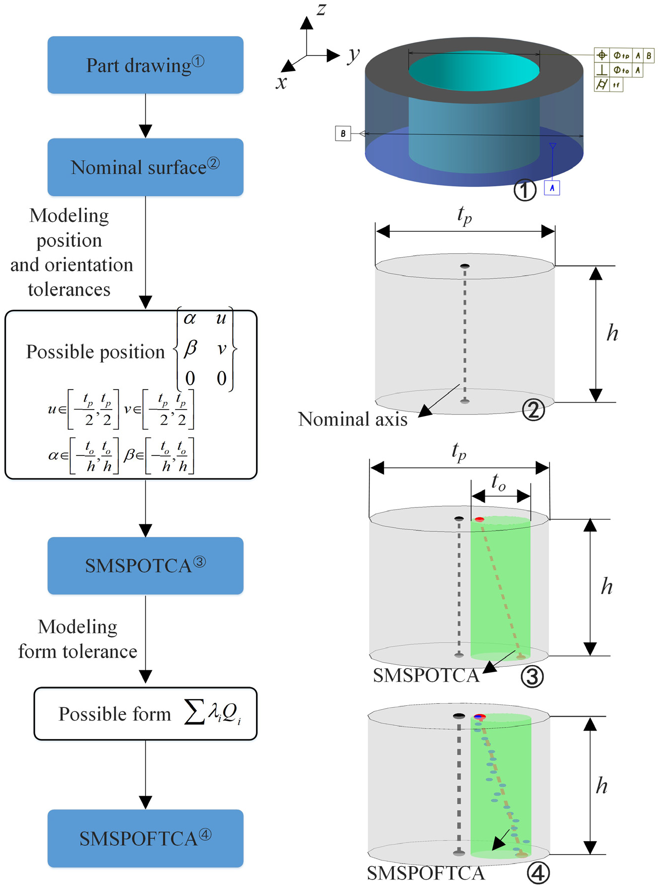
Modeling skin model shapes for cylindrical surfaces.
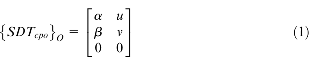
The deviation torsor includes two rotations and two translations:
A rotation about x axis by an angle
A rotation about y axis by an angle
A translation along x axis by a distance u
A translation along y axis by a distance v
Possible vales of the deviation torsor should be within the range:
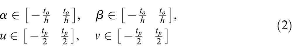
where h represents height of the cylindrical surface.
Moreover, based on the constraints of the tolerance zone, values of the deviation torsor should satisfy the following relation:
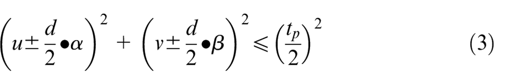
where d represents the diameter of the cylindrical surface.
Based on equations (2) and (3), valid pairs of
Form defects
As for form defects, various modeling methods have been proposed in the field of CAT. In the early design stage, random noise, mesh morphing, 28 and modal based methods 29 are typical methods,25,30 while Statistical Shape Analysis (SSA) methods are often used in the observation stage. 9 Specifically, for the cylindrical surface, the Legendre-Fourier (L-F) Polynomials 23 are adopted in the current paper to model form defects based on the design value of form tolerance tf. Based on Ni and Yao, 23 all defects of the cylindrical parts, can be decomposed into a series of L-F functions, and each L-F function normally corresponds to an error source in the manufacturing system. Therefore, using L-F polynomials to model form defects of cylindrical surfaces is quite a decent choice. Moreover, it can provide manufacturing engineers with a guideline to investigate the sources of manufactured errors by analyzing the observed geometric defects.
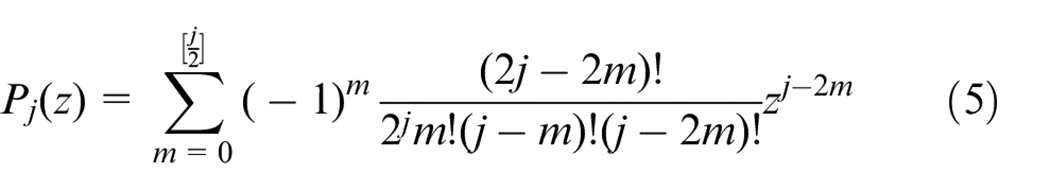
In the L-F functions, the Fourier series are used to model the roundness error in the radial direction and the Legendre polynomials are used to model form defects in the axial direction. Legendre polynomials are the polynomial solutions to Legendre’s differential equation, and they can be expressed using Rodrigues’ formula: 23
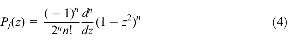
The above equation can be further deduced as:
where
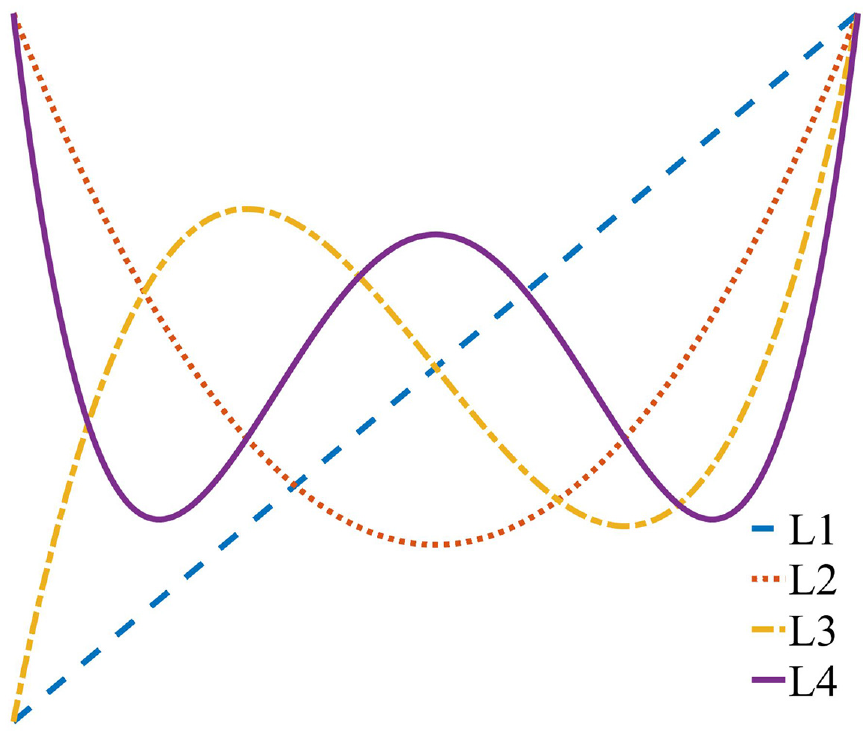
Plot of the Legendre polynomials.
Then, the complete form of the L-F functions can be described as: 23
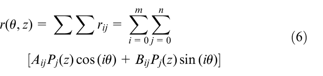
where
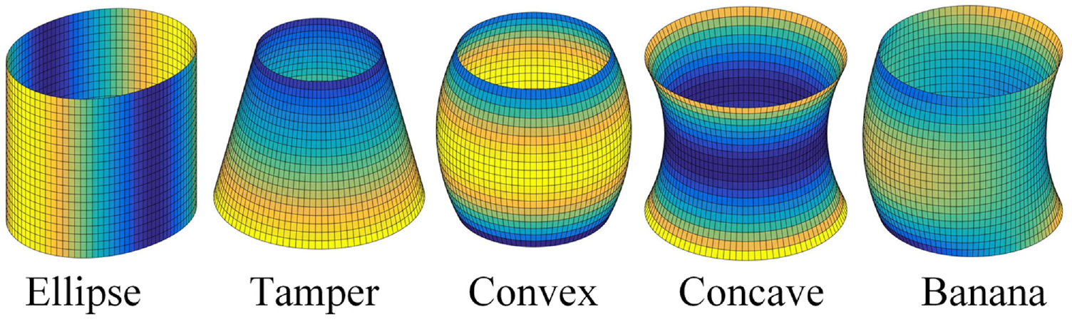
Typical forms of defects of cylindrical surfaces.
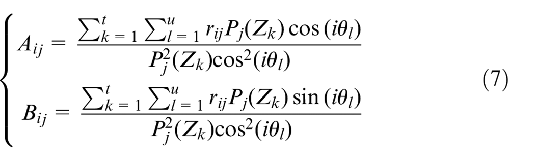
Hence, the modeling of form defects of cylindrical form defects is the summation of a series of L-F functions. Here, Sf. denotes the form defects. Moreover, the orthogonality of the L-F polynomials is one of the most important properties. For a given cylindrical surface, once the specific measured data are obtained, the coefficients of the L-F polnomials can be readily calculated by: 23
It should be noted that the values of

It has to be noted that a randomly generated surface based on Eq. (8) may not be in accordance with the given tolerance specification. Hence, a scaling operation 31 should be performed after generating the surface.
Tight fit and loose fit
For a pair of assembled cylindrical surfaces (such as shaft and holes), there may be two totally different situations: “tight fit” situation and “loose fit” situation. The former one means that the two cylindrical surfaces may lead to interference and penetration. The latter one means the two cylindrical surfaces lead to non-interfering part positions. For the two different situations, the simulation methods of their positioning are different. Hence, the very first step to determine the positions of a given pair of cylindrical surfaces with form defects is to distinguish whether it is tight fit or loose fit. Before that, the corresponding skin model shapes of the cylindrical surfaces are generated by using the method proposed in the former section.
Based on the concept of the feature operations (association, construction, etc.) of ISO - GPS standard, 32 the cylindrical surfaces will be cut by several planes at first. Then, the associated circle is computed by roundness measurement methods: Least Square Circle (LSC), Minimum Circumscribed Circle (MCC) or Maximum Inscribed Circle (MIC). A comparison of these fitted circles is illustrated in Figure 4, and the black dots are the discrete points.
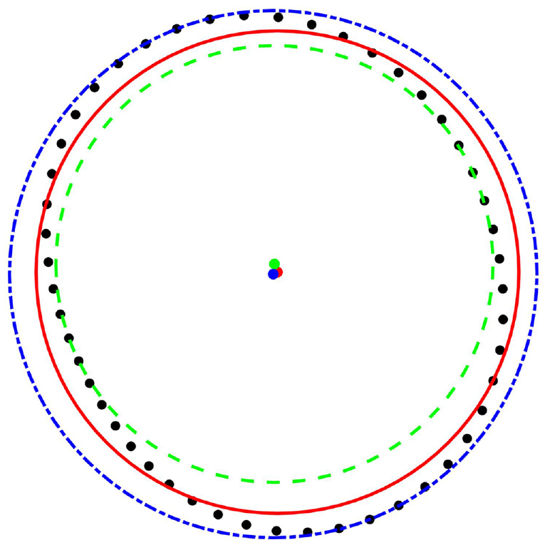
A comparison between LSC, MCC, and MIC.
For Cylindrical surfaces of shaft features, the MCC will be used. There will be several calculated MCCs corresponding to the cutting planes, and we denote the maximum of them as Rmax. For Cylindrical surfaces of hole features, the MIC will be used. Similarly, there will be several calculated MICs corresponding to the cutting planes, and we denote the minimum of them as rmin. If Rmax ≤ rmin, the specific pair of the cylindrical surfaces is definitely loose fit. This means that there will be no gap, no matter what the relative position of the shaft and hole is. For this situation, the positioning for loose fit of all possible positions can be simulated. If Rmax > rmin, the pair of the cylindrical surfaces may be loose fit or tight fit. To furthrt determine, the Iterative Closest Point (ICP) strategy 33 is firstly used here. Details of the ICP method will be explained in the next section. Thereafter, the loose fit and tight fit situation can be determined based on the ICP results. If there is penetraion, the pair of the cylindrical surfaces is tight fit. Otherwise, it is loose fit. It has to be noted that in this situation, it is possible that there will be no peentration for only some possible positions.
Based on the above discussion, Figure 5 shows the determination process of loose fit and tight fit. Examples of tight fit and loose fit are given in Figures 6 and 7, respectively. In Figures 6 and 7, the green points are the discrete sampling points of the cylindrical surface, and the black and red points are the MIC and MCC center points.
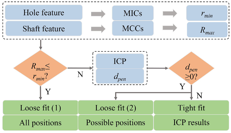
The determination process of loose fit and tight fit.
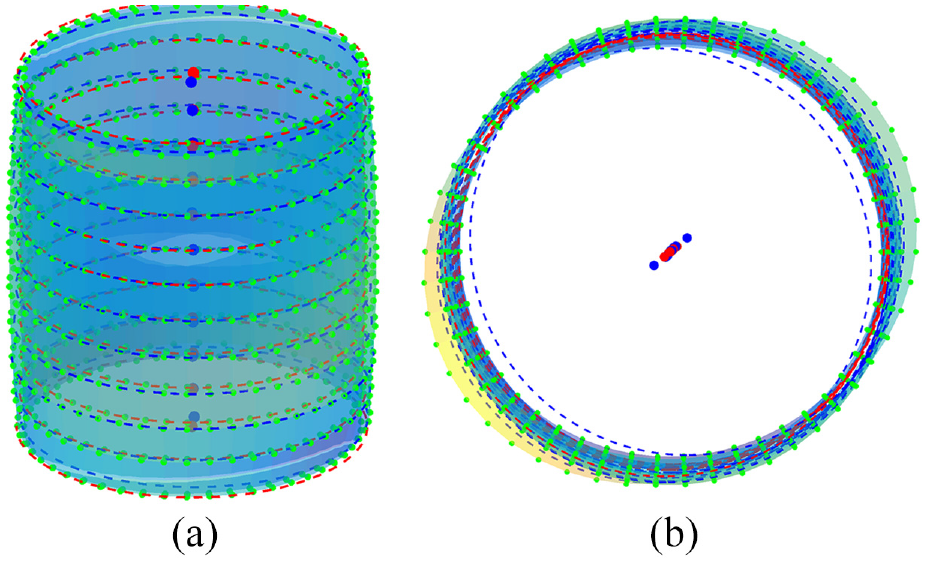
An example of tight fit: (a) 3D view and (b) top view.
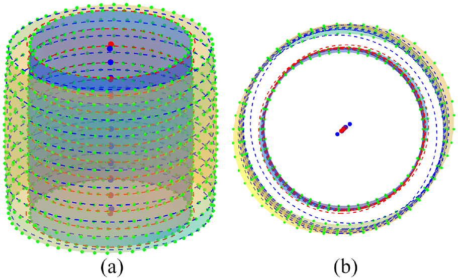
An example of loose fit: (a) 3D view and (b) top view.
Simulation of tight fit
For the situation of tight fit, to make the shaft and hole perfectly match, there must be the mating forces which lead to small elastic deformations. Here, the relative positioning of the cylindrical surfaces is simulated by adopting the ICP strategy 33 from a pure geometrical analysis. The ICP strategy is widely used for the registration of 3D data point clouds to model shapes. It is a well-known approach to solve registration problems, which is the minimization of an error metric defined on pairs of points. Points from the model shape stay unaffected, and the corresponding points from a data shape are translated and rotated to fit the reference shape. Here, the simulation would consequently result in slight part interferences, and it is assumed that these interferences may have deformed into a non-interference condition. The basic idea of the ICP strategy is given as follows:
Make the points of the cylindrical surfaces of the corresponding hole feature as the data shape
Find the transformation that minimizes an objective function. Here, the objective function used is the sum of squared Euclidean distances between the points in the data shape and the corresponding points in the model shape.
Apply the transformation to the data shape and calculate the relative error. If it is less than the predefined error or the iteration reaches the maximum number, stop the iteration, otherwise start again from the first step.
The ICP method has been developed a lot over the years and different improvements have been proposed.34,35 Here, a k-d tree method 36 is used to accelerate the iteration. As shown in Figure 8(a), the red solid points represent the points of the cylindrical surface of the hole feature and the blue hollow points represent the points of the cylindrical surface of the shaft feature. After the k-d tree based ICP calculation, the relative positioning of the cylindrical surfaces is shown in Figure 8(b). For this given example, the calculation only takes 0.043 s and 25 times iteration make the convergence come to a very ideal state. The simulations were conducted on the author’s ordinary desktop computer (Windows 7 operating system, 3.20 GHz Intel Core i7-6900K CPU and 64 GB RAM).
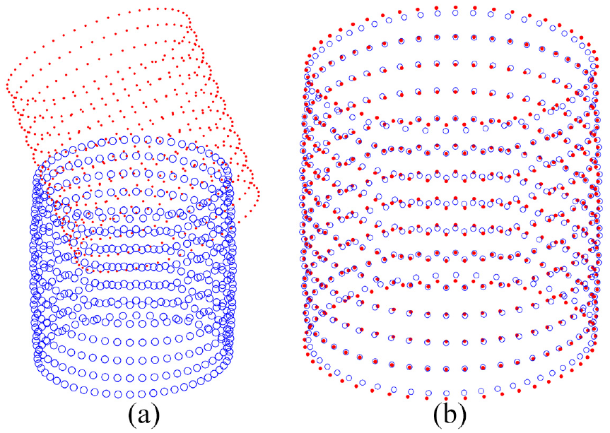
Illustration of the simulation of tight fit situation: (a) the initial cylindrical surfaces and (b) the ICP calculation results.
Based on the ICP simulation result, the relative position of the cylindrical surfaces can be deduced. Meanwhile, where the interferences occur can be easily determined, which may offer useful information for the assembly of the shaft and hole components.
Simulation of loose fit
For the simulation of loose fit, the basic idea is shown in Figure 9. At first, with the consideration of form defects, an initial positioning of the cylindrical surfaces is determined. Thereafter, the surface deformations are calculated only near the contact area. These deformations may further affect the positioning of the cylindrical surfaces.
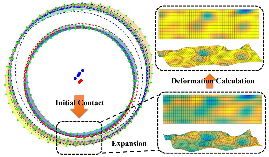
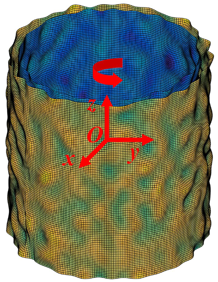
Illustration of the consideration of surface deformations for cylindrical surfaces.
For the loose fit situation, the shaft feature is always smaller than the hole feature, which may lead to different positioning when the contact occurs at different areas. Hence, the simulation in this section investigates the different positioning based on where the contact occurs. Here, the cylindrical surface of the hole feature is defined as the reference surface, and the cylindrical surface of the shaft feature as target surface. As shown in Figure 10, it is defined that the contact will occur along the x-direction and the initial angles of both of the surfaces are 0. If the target surface rotates around the z-direction, the contact will be different, similarly the rotation of the reference surface. In the current paper, the contact is simulated every 60°. Hence, there will be 36 different cases on total, such as the case in which the reference surface rotates 240° and the target surface rotates 120°.
An example of a pair of cylindrical surfaces.
Both of the cylindrical surfaces with form defects are generated based on the modeling method of skin model shapes. In this given example, the height of the surfaces are 20 mm. Ideal radius of the hole and shaft are 10 and 9.85 mm, respectively. Both of the form tolerances are 0.1 mm. For this given example, the sampling points along the height direction and around the circle are 101 and 360, respectively.
Consideration of form defects
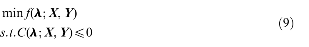
To determine the positioning of the cylindrical surfaces with only the consideration of form defects, the constrained registration approach 10 is adopted here. The method is supposed to obtain an optimal transformation of the target surface while satisfying the following two constraints:
The distance between any corresponding points pairs on the two features should be minimized, that is, an objective function f.
The two point sets shall not interpenetrate with each other, that is, a constraint function C.
The transformation of the target surface can be represented by
According to Schleich and Wartzack,
13
the objective function f can be the Hausdorff distance, the sum of squared distance, the sum of signed and unsigned distance, etc. However, based on systematic trials and comparisons,
37
the sum of absolute signed normal distances
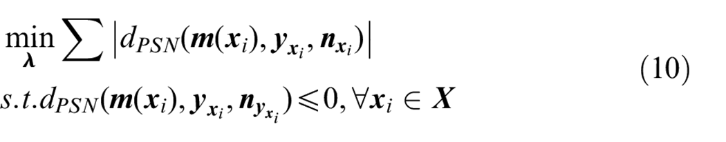
where
The numerical solution of this constrained optimization problem can be performed by employing an active set method. A more detailed explanation of the constrained registration approach can be found in Schleich and Wartzack.
13
Based on the constrained registration approach, the simulation of the loose fit condition with consideration of form defects can be conducted. Here, the contact is simulated every 60°. As given in Figure 11, the example of the simulation is illustrated when both of the angles of the cylindrical surfaces are set to 0°. Based on the simulation results, the positioning of the target cylindrical surface can be calculated, which is represented by:
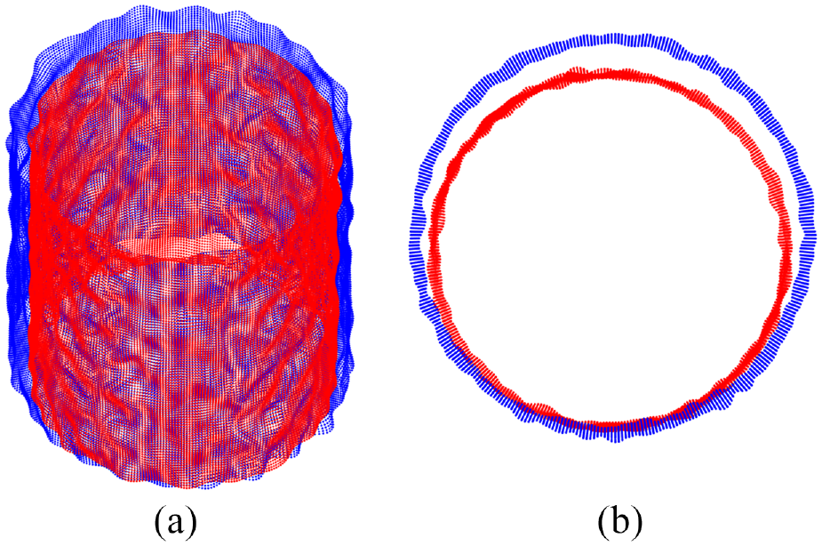
Illustration of the constrained registration result when both of the angles of the cylindrical surfaces are set to 0°: (a) 3D view and (b) top view.
Positioning of the target cylindrical surface for different cases.
Consideration of surface deformations
The former subsection considers the effects of form defects on positioning of the cylindrical surfaces. This subsection will further explore the effects of surface deformations. The interactions of form defects and surface deformations in CAT field have attracted more and more concerns but few research outcomes deal with cylindrical surface situations.15,19–21 Here, the Conjugate Gradient-Fast Fourier Transform (CG-FFT) method is adopted to calculate the surface deformations. Under the assumption of frictionless non-adhesive contact, the contact of two non-ideal surfaces can be equivalently replaced by the contact of one-ideal surface and one non-ideal surface. 38 For the case of two cylindrical surfaces, it is also replaced under the above assumption in the current research. Taking Figure 11 for example, in which both of the angles of the cylindrical surfaces are set to 0°, the equivalent non-ideal surfaces are shown in Figure 12(a). In this equivalent replacement process, the cylindrical surfaces transformed into rectangular ones. Moreover, because the contact only occurs in a small area of the cylindrical surfaces, only the cylindrical surfaces near the contact area are used for each calculation as shown in Figure 12. Then, physical properties, including assembly force and material elasticity, are considered and the elastic displacement of the discrete points in the equivalent non-ideal surface can be calculated as: 21
where M and N represent the number of discrete points in the length and width directions, respectively; p represents the contact force on each discrete point; and K denotes the matrix that collects the influence coefficients, which can be calculated as:
where
with
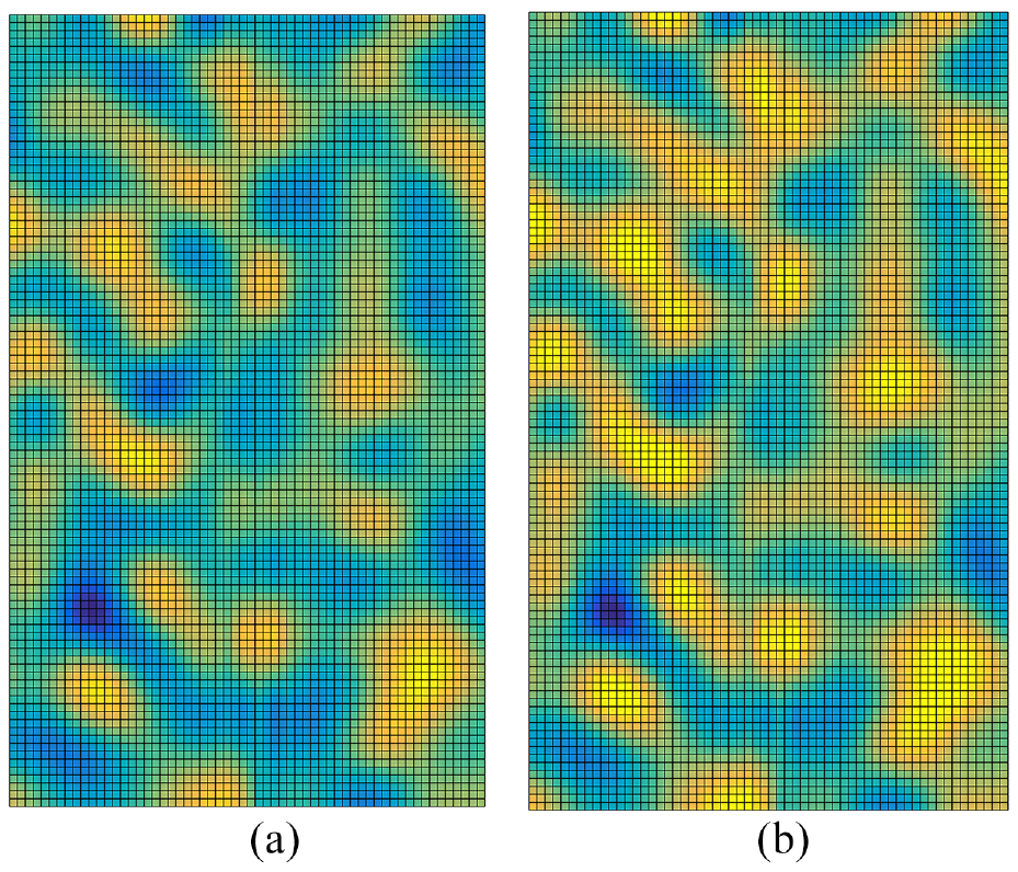
Illustration of the surface deformations: (a) initial state and (b) after the surface deformations.
To ensure that there is no penetration between the two contacting surfaces and the discrete points do not bear negative forces, the following restrictions should be fulfilled:
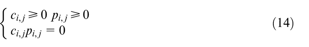
where
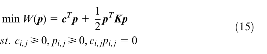
To solve the minimization problem given in Eq. (15), the CG-FFT method is used which applies the Conjugate Gradient (CG) algorithm to search the gradient direction, and the Fast Fourier Transform (FFT) method to compute Eq. (11) efficiently.
For the given example shown in Figure 12,
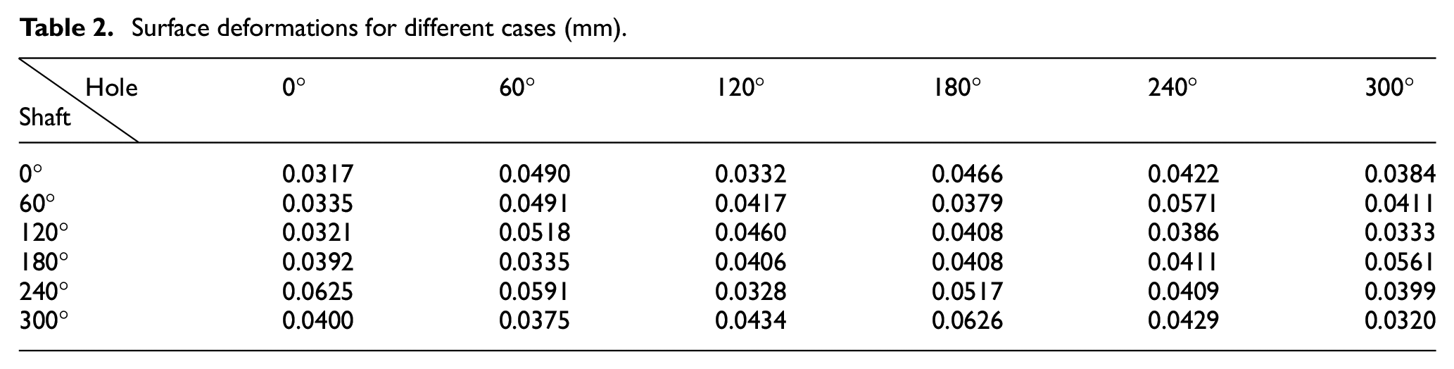
To quantitatively show the deformation, the displacement of the ideal surface is calculated. For the case in Figure 11, the calculated displacement is 0.0317 mm. Table 2 further lists displacements for all of the 36 cases, in which the unit of the displacement is mm. It can be seen that, for different cases, the deformations vary a lot. Hence, the initial positioning of the cylindrical surfaces caused by the form defects, also have a considerable effect on the surface deformations.
Surface deformations for different cases (mm).
After calculation of the surface deformations, the new positioning of the cylindrical surfaces can be calculated. In the current calculation, the rotational angles will not change. Only the translations further change along the considered direction (i.e.
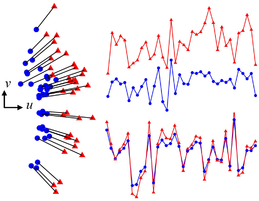
The changes of the translations with consideration of surface deformations.
Discussion
Based on the above calculations, it can be seen that for the different initial angles of the two cylindrical surfaces, the calculated positioning result is different. It is because that the form defects in different areas of the cylindrical surfaces are different, which may also further affect the surface deformations. For a given pair of cylindrical surfaces, with early simulation of the positioning, we can conclude in which angle the variation will be smallest. It is very useful information for realistic assembly. Moreover, if we want to control the surface deformation or we care about the positioning with consideration of deformations, the simulation can also provide an optimal initial angle of the to-be-assembled cylindrical surfaces.
For the specific simulated cylindrical surfaces in the current paper, the variation of translation, that is,
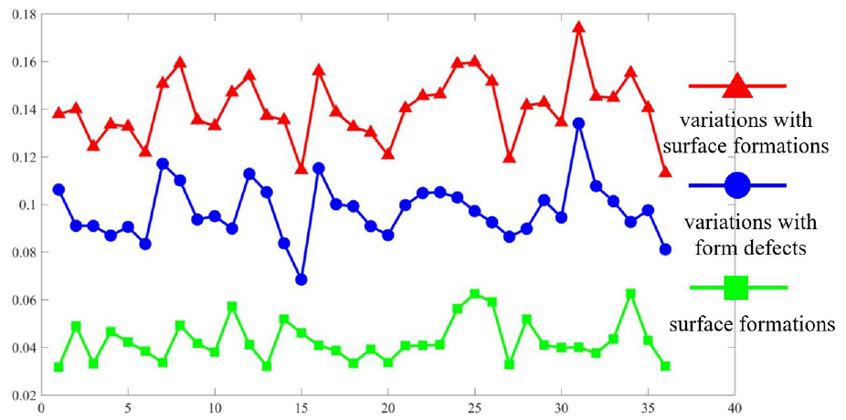
The variations of translation.
From Figure 14, it can be seen that only with consideration of form defects, case 15 generates the minimal variation of translation; case 1 has the minimal surface deformations, but very close to case 13, 27, and 36; with consideration of surface deformations, case 36 results in the minimal variation, but very close to case 15. Hence, based on the above information, the optimal to-be-assembled angle can be determined based on which variation is the optimization goal.
Conclusions
Cylindrical surfaces are very common and important in mechanical parts. The modeling and simulation of them with consideration of form defects have led to a number of considerable research outcomes in the field of CAT. However, further consideration of surface deformations caused by external forces still remains a challenge. To address this issue, this paper properly considers the form defects and surface deformations for tolerance analysis of cylindrical components. The tight fit and loose fit of a pair of cylindrical surfaces with form defects were firstly identified based on the modeling of skin model shapes. For tight fit situation, a k-d tree based ICP algorithm was used, and for loose fit situation, the constrained registration approach was adopted. To further consider the effects of surface deformations, the CG-FFT method was presented for loose fit situation. The simulation results revealed that both form defects and surface deformations had effects on the positioning of the cylindrical surfaces, and the form defects had a considerable influence on the results of surface deformations. Moreover, the simulated results can help determine how to obtain the best performance of the to-be-assembled cylindrical surfaces. In addition, in the design station, the simulation process may also help determine a more reasonable and refined tolerance scheme.
Footnotes
Declaration of Conflicting Interests
The author(s) declared no potential conflicts of interest with respect to the research, authorship, and/or publication of this article.
Funding
The author(s) disclosed receipt of the following financial support for the research, authorship, and/or publication of this article: This research was supported by the National Natural Science Foundation of China (Grant No. 51935003), and the China Scholarship Council (CSC).