
Abstract
In the field of ultra-precision machining, the dynamic performance of ultra-precision equipment contributes a lot to the processing accuracy. In this paper, in order to study the dynamic performance of the flycutting machine tool, the virtual material method was adopted creatively to build a machine tool model. This method overcame the complexity of actual structure and obtained more accurate results than traditional methods. Subsequently, the finite element method was applied to analyze the dynamic performance of the virtual material model. Furthermore, the modal test for the flycutting machine tool was performed to verified the simulations by means of the one-point hitting and multi-point measurement. The simulation results indicate that the virtual material model has high comprehensive accuracy, of which the average error of natural frequency is 5.9% and errors are all less than 6% excepting the first order. Moreover, combined with the flycutting experiments, it can be found that the fifth order mode of machine tool contributes a lot to processing quality, which leads to the waviness of 53 mm on the machined surface directly because of the weak stiffness of beam-column joints. By increasing the stiffness of the key joints, the waviness can be eliminated, which greatly improves the surface quality of the workpiece.
Keywords
Introduction
In the field of ultra-precision machining, the dynamic performance of ultra-precision equipment is the emphasis of researches since it makes a great influence on the machining accuracy. At the design stage, the dynamic performance must be take into account to evaluate the processing quality.1,2 In particular, the dynamic performance of the ultra-precision flycutting machine tool has a significant impact on the surface quality due to its special processing way. 3 Large diameter optical components processed by the ultra-precision flycutting machine tool can achieve high accuracy, which surface accuracy is less than 1 mm, and the roughness is less than 3 nm. Chen et al.4,5 presented a two-round method to design a flycutting machine tool, and further studied the multi-mode vibration of the machine tool and its influence on surface generation. Liang et al. 6 analyzed the kinematic chain of machine tool and built a dynamic model to predict the surface topography.
As for high-precision machine tools, the dynamic stiffness of more than 60% and the damping of about 90% in the whole structure come from the joints.7,8 Thus, in a series of dynamic modeling researches, modeling for the joints has become the key to study the dynamic performance of the entire machine tool. The simplest modeling method is connecting the structures rigidly. Since the contact stiffness is far from the reality, this method would introduce big errors. So that it is only applicable to some small components which have few impact on the whole machine. A classic method for joints modeling is the spring-damper model. By this method, the spring-damper elements are added into the interfaces to simulate the kinematics of the joint. Furukawa and Moronuki 9 used spring elements to express the sliding interfaces and built the kinematic model. The displacements in three directions were obtained by this model. Namazi et al. 10 established the tool holder–spindle joint model by arranging translational and rotational springs symmetrically. And the dynamic response of the joint was identified. The spring-damper elements was widely used in dynamic modeling. However, the accuracy of the spring-damper model is hard to further improve, because actual joints are non-linear while spring-damper elements are non-coupled.11,12 So that the virtual material method was proposed for higher accuracy. Desai et al.13,14 presented a thin-layer element to simulate the soil-structure interaction in geomechanics. Then Ahmadian et al. 15 and Ahmadian and Jalali 16 introduced the thin-layer element into the surface-to-surface joints to study its dynamic performance. The stiffness and damping were identified by combining the simulations and experiments. In 2011, Tian et al.17,18 proposed an analytic method of virtual material. The material properties of the virtual material such as elastic modulus, shear modulus, Poisson ratio and density were deduced based on Hertz theory and GW model. Iranzad and Ahmadian 19 built a virtual material model for bolted joints to study its non-linear phenomenon. And the model was validated by the frequency response function (FRF) measurement.
Although there are many researches on the virtual material method for bolted joints, it is still difficult to apply it on the entire machine tool due to the complexity of structure. In this paper, in order to explore the dynamic performance of the whole flycutting machine tool, the virtual material method was adopted to build the machine tool model for higher comprehensive precision. And the finite element method (FEM) was used to analyze the dynamic performance of the machine tool, such as the natural frequencies, damping ratios and vibration modes. Simulations were verified by the modal test. Furthermore, through experiments of cutting optical lens, the weak link of the machine tool which have a great influence on machining were found and optimized.
Virtual material model of flycutting machine tool
Virtual material theory for joints
As demonstrated in Figure 1, the ultra-precision flycutting machine tool is mainly composed of a bed, two columns, a beam, a hydraulic feed slide installed on the bed and an aerostatic spindle installed on the beam. In the gantry structure, the beam and columns, the columns and the bed are bolted respectively. The spherical pairs are employed between the beam and columns to adjust the space posture of the beam in two-dimension, whose connection stiffness is weak. It has been found that the dynamic performance of some key components is closely related to the medium and high frequency waviness on the machined surface. The regular waviness is usually caused by the components in poor stiffness.20,21
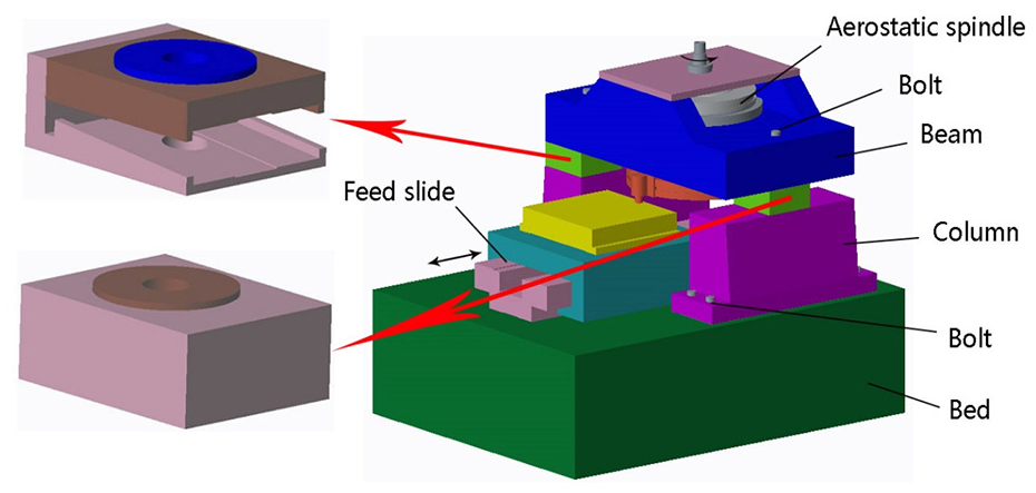
Structure of the flycutting machine tool.
In order to study the influence of the entire machine tool on the machined surface, it is significant to study the dynamic performance of the gantry structure. The key to establish an accurate machine tool model is to model joints accurately, so that two beam-column joints and two column-bed joints were selected as the key joints to study their dynamic performance. The dynamic modeling for joints has high theoretical difficulty. Taking simplicity and accuracy into account, virtual material method was adopted to establish the bolted joints model.
As shown in Figure 2(a), contact conditions of actual joints depend on surface topography of interfaces, materials of the structures, pressures, and so on, so it is difficult to establish an accurate kinetics model of joints directly.22,23 As exhibited in Figure 2(b), the joints model based on the virtual material method regards the contact surfaces as smooth surfaces and adding an extra thin layer inside two structures, which has little effect on the entire machine tool model. The material of the layer is defined as an orthotropic material and the layer combines with structures rigidly. Through the customization for the material characteristics, the dynamic performance of the entire virtual joint can approximate to the actual joint.
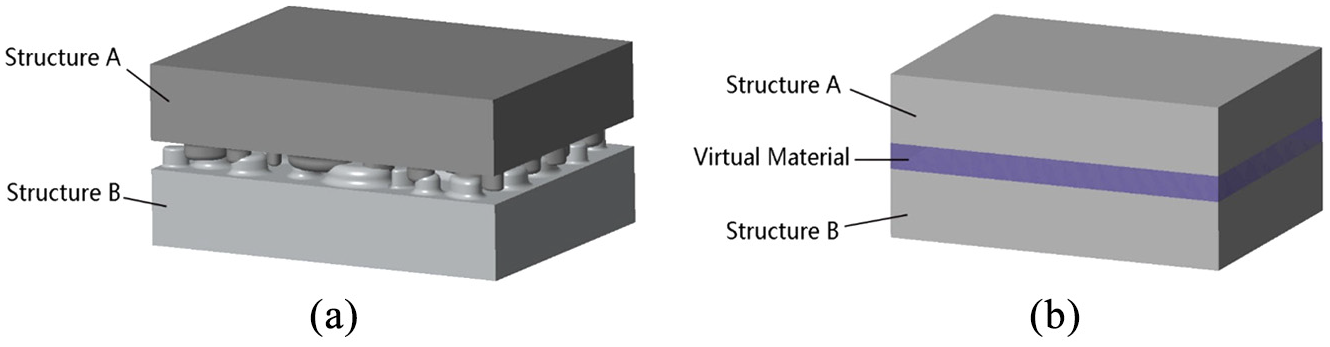
(a) The actual contact model and (b) the virtual material model.
Referring to the dynamic equation of the multiple degrees of freedom system, the dynamic equation of the joints based on the virtual material method is exhibited as 24 :
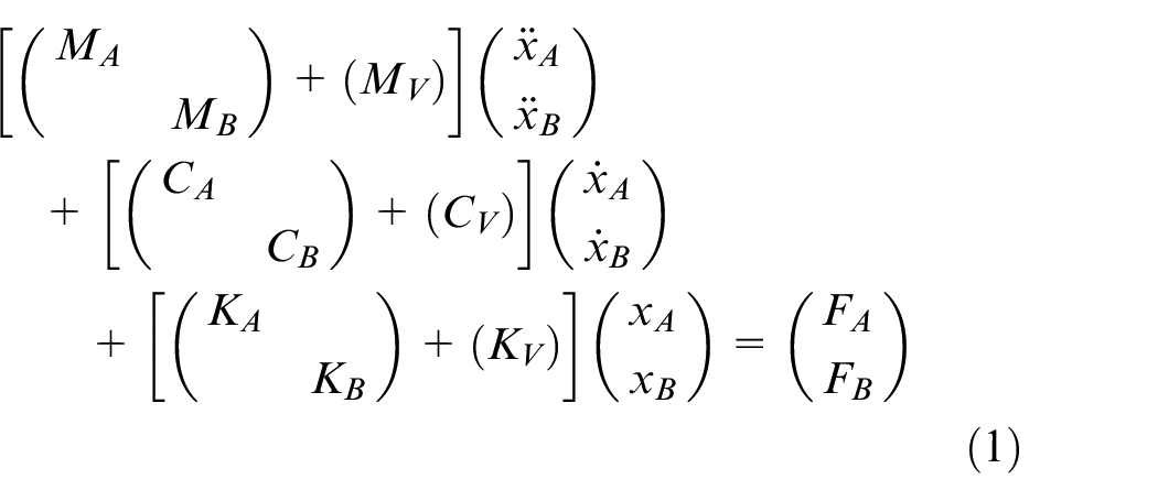
where, MA, MB, and MV are mass matrices of the Structure A, the Structure B and the virtual material layer, respectively. CA, CB, and CV are damping matrices of the Structure A, the Structure B and the virtual material layer, respectively. KA, KB, and KV are stiffness matrixes of the Structure A, the Structure B and the virtual material layer, respectively. xA and xB are displacements of the Structure A and the Structure B. FA and FB are the pressures on the Structure A and the Structure B.
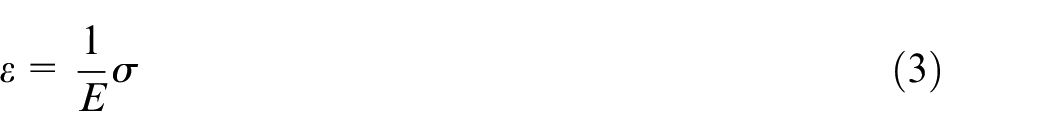
The deformations are considered to be within the elastic limit of the materials. There is no tension-shear coupling in orthotropic materials. The constitutive equation of the orthotropic materials in the Cartesian coordinate system is expressed as:
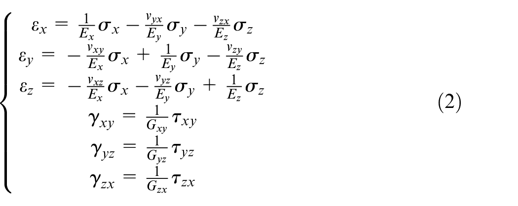
where, ε, σ, γ, and τ are the strain tensor, the stress tensor, the shear stress, and the shear strain, respectively. E and G are the elastic modulus and the shear modulus.
Assuming the stress acts in a normal direction, there is:
The material properties are expressed by elastic model, shear modulus and density, while the dynamic characteristics of joints are usually expressed by stiffness and damping. To achieve the conversion between actual joints and virtual material models, the elastic modulus and shear modulus can be obtained according to:
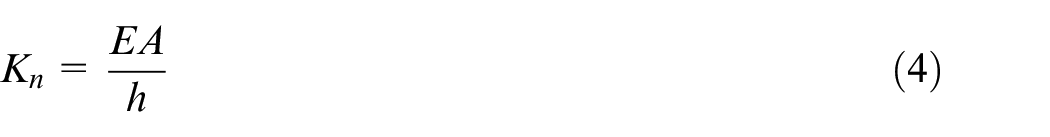
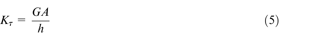
where, Kn is the normal tensile stiffness. A is the contact area. h is the thickness of the virtual material layer. Kτ is the shear stiffness.
Density of the virtual material in the bolted joint model can be deduced by 17 :
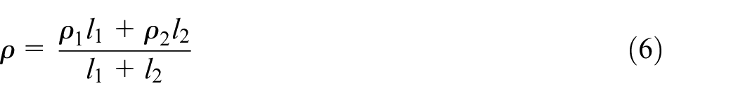
where, ρ is density of the virtual material; ρ1 and ρ2 are densities of the structures in both sides of the interface; l1 and l2 are bonding lengths of the bolts in both sides.
Considering the actual constraints of the key joints in the gantry structure, the beam-column joints and the column-bed joints in the machine tool only subject to normal tensile stress thanks to the symmetrical structure. Thus, the virtual material can be defined as isotropic material without the shear force.
Identification of the key joints
In the virtual material theory, the material properties of the virtual material are determined by the contact characteristics of the joint. The stiffness and damping of joints can be obtained from the frequency response functions (FRFs) by the half-power-band method. The modal test was adopted to get the frequency response functions of the joints. Four key joints, two beam-column joints, and two column-bed joints, were tested successively. The devices for modal tests are exhibited in Figure 3. Taking the left beam-column joint as an example, an acceleration sensor was located on the left of the beam. By impacting the left column with a rubber hammer, the frequency response functions were obtained through the acquisition system and showed on the computer. The frequency response function of the left column-beam joint is shown in Figure 4.
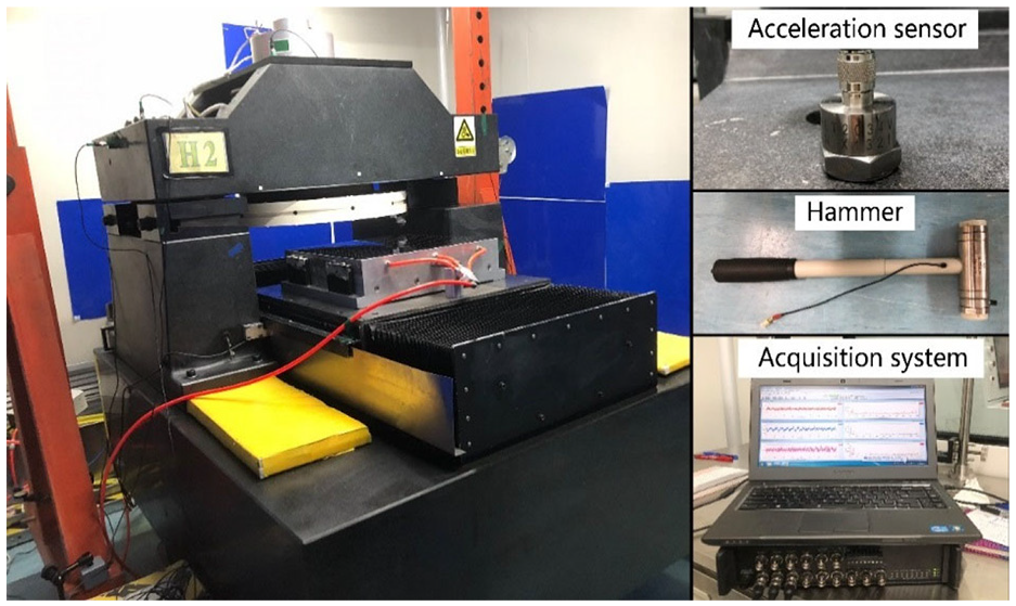
Devices for the identification.
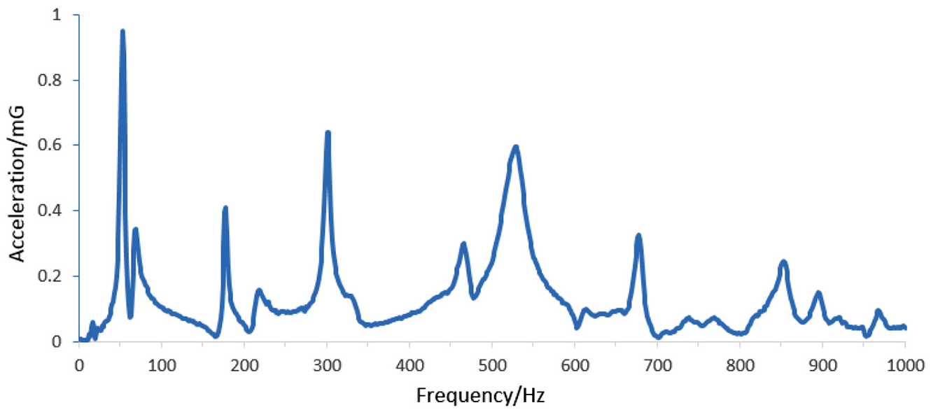
The FRF of the left beam-column joint.
As demonstrated in Figure 4, the first four orders with high peaks were selected for analysis. The natural frequencies are 53.75 Hz, 177.5 Hz, 300 Hz, and 526.25 Hz, respectively. The stiffness and damping of each order were deduced according to the half-power-band identification method, as shown in equations (7) and (8).


Where, Kn and Cn are the stiffness and damping of the joint in the nth order, m is the equivalent mass, fn is the natural frequency in the nth order, and Δfn is the half-power-band in the nth order.
The first four orders of stiffness were calculated as 8.65 × 10⁷ N/m, 9.43 × 10⁸ N/m, 2.70 × 10⁹ N/m, and 8.29 × 10⁹ N/m, respectively. And the first four orders of damping were calculated as 3.69 × 10⁴ N s/m, 1.55×10⁴ N s/m, 3.36×10⁴ Ns/m, and 1.31×10⁵ Ns/m, respectively. Taking the reciprocal of natural frequency as the weights, 25 the weights of the four orders were 0.63, 0.19, 0.11, and 0.07, respectively. So that the total stiffness of the beam-column joint was 1.11 × 10⁹ N/m, and the total damping was 3.91 × 10⁴ N s/m. In this way, the parameters of the other three joints were also deduced.
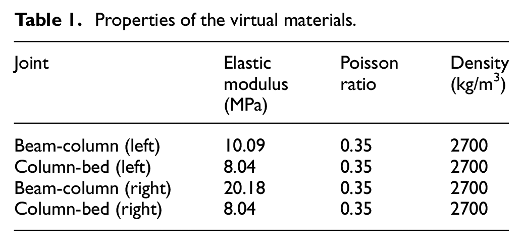
The elastic modulus of the virtual material was obtained by equation (4), in which the stiffness was known. As well as the elastic modulus of the other three joints can be obtained. The Poisson ratio was 0.35 since the shear modulus was not considered. The beam, columns and bed are all made of marble, so that the density of the virtual materials was deduced as 2700 kg/m3 from equation (6). The properties of the virtual materials of four key joints are listed in Table 1.
Properties of the virtual materials.
Modal analysis and modal test of the machine tool
Modal analysis of the flycutting machine tool
Referring to the actual structure of the flycutting machine tool, a 1:1 three-dimensional model was built in PTC Creo software. The simulation processing of aerostatic bearing has been introduced in author’s other researches. The structure of the spindle system is meshed by the tetrahedral mesh to refine the mesh of the supporting surface, which divides a total of 40,944 meshes and 70,565 nodes. As is illustrated in Figure 5 26 The virtual material layers with thickness of 1 mm were added into the beam-column interfaces and the column-bed interfaces. Subsequently, a finite element analysis software, ANSYS workbench, was employed to conduct the modal analysis of the whole machine tool. The material properties of the virtual materials were defined as Table 1 listed. As shown in Figure 5(a), the virtual material layers were bonded with the actual structures. And elastic supports were applied on the hydraulic slide and the aerostatic spindle to simulate their working conditions. Besides, the model was meshed into 43,282 elements with 131,926 nodes as shown in Figure 5(b). The modes in the range of 0–300 Hz were analyzed, and the first five vibration modes are exhibited in Figure 6.
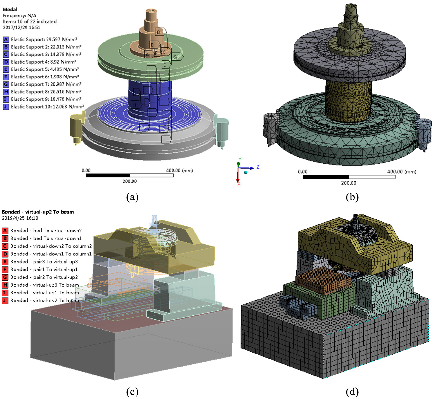
Setting of modal analysis: (a) constraints of the spindle system, (b) Mesh of the spindle system, (c) constraints of the model, and (d) Mesh of the model.
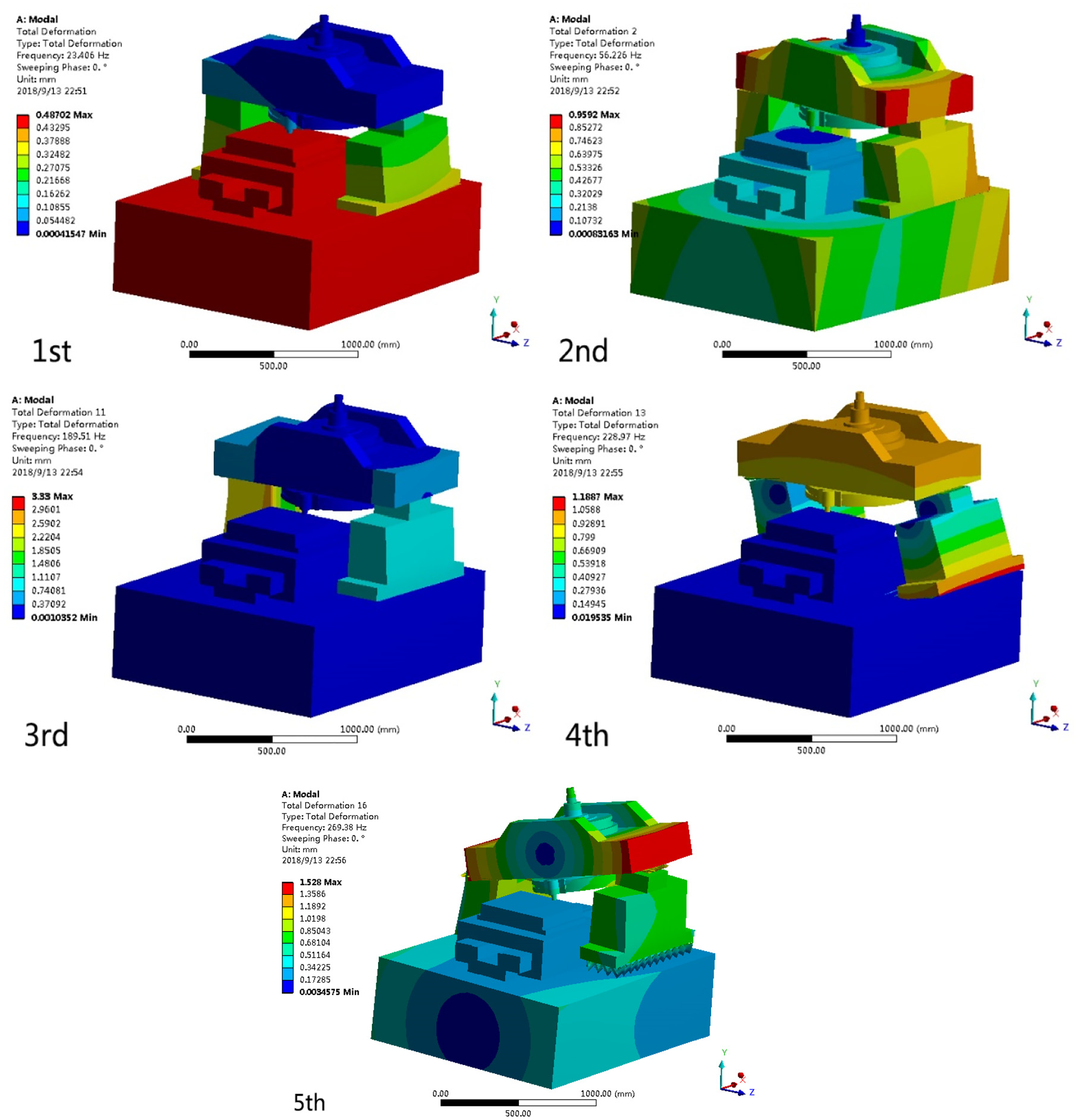
Modes of the flycutting machine tool.
As demonstrated in the Figure 6, the first five natural frequencies of the flycutting machine tool are 23.406 Hz, 56.226 Hz, 189.51 Hz, 228.97 Hz, and 269.38 Hz. The large deformation appears on the beam and columns. The deformation in the first four modes is mainly caused by the movement or rotation of the beam on the X-Z plane. So that the movement of tool tip is mostly on the X-Z plane as well. However, the deformation in the fifth mode is introduced by the rotation of the beam around the X axis. This movement leads to the displacement of the tool tip along the Y axis, which is exactly sensitive to the processing quality. Obviously, the fifth mode of 269 Hz makes a great influence on the machined surface.
Modal test of the flycutting machine tool
In order to verify the accuracy of the simulation, the modal test was carried out on the entire flycutting machine tool. The experimental devices include a rubber hammer, an acceleration sensor and an acquisition system as well, as exhibited in Figure 3. A corner of the bed away from the spindle was chosen as the impact point, and 102 measuring points were scattered around the entire machine tool. By knocking the impact point and moving the sensor to each measuring point, the frequency response functions of all measuring points were measured in turn.
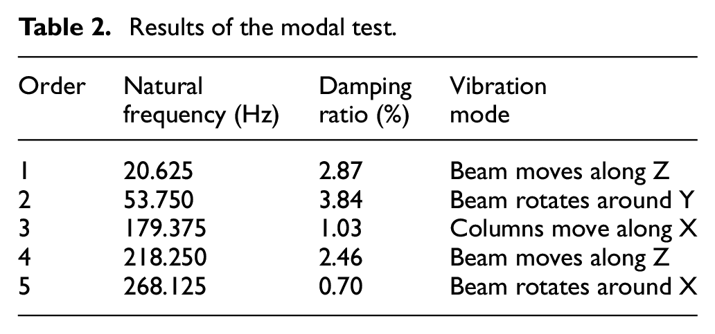
As demonstrated in Figure 7, the frequency response functions of all measurement points were averaged. The natural frequency, damping ratio, and vibration mode of the flycutting machine tool were analyzed from the modal test, as listed in Table 2.
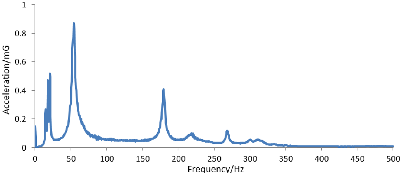
Average FRF of the machine tool.
Results of the modal test.
The natural frequencies of the simulation were compared with the test ones, as demonstrated in Figure 8. The simulation based on the virtual material method has high precision, of which average natural frequency error is 5.9%. And the errors are less than 6% excepting the first order. Especially, the error of the fifth order is only 0.5%. Moreover, the simulation and the test own the same vibration modes, which indicates that the simulation based on the virtual material method is reliable. It can be found from the vibration modes that the 5th order of vibration mode is pretty sensitive to processing quality since the beam deforms a lot along the cutting depth feeding direction.
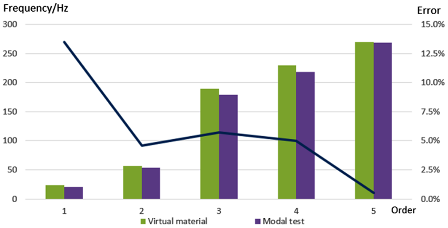
Comparison between the simulation and test.
Flycutting experiments
Experiments with different bonding stiffness
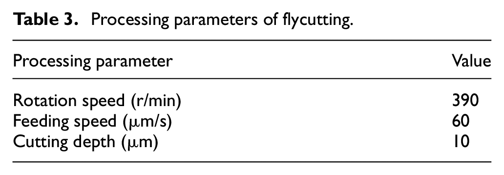
In order to explore the influence of the dynamic performance of the joints on the processing quality of the machined surface, two groups of flycutting experiments were carried out under different contact conditions of the joints. The subjects were potassium dihydrogen phosphate (KDP) crystals and the machining parameters are listed in Table 3. By analyzing the surface topography and relating it to the contact conditions of the joints, the effect of the joints on processing would be known.
Processing parameters of flycutting.
In the first group, the bolt preload torque of the beam-column joints was only 30 N·m, which means the joints have a weak stiffness. The machined surface topography is exhibited in Figure 9(a) and the waviness of the section is extracted in Figure 9(b). In the second group, the preload torque of the joints increased to 50 N·m. And the flycutting processing was performed once again at the same processing parameters. The surface topography is exhibited in Figure 10(a) and the waviness is extracted in Figure 10(b).
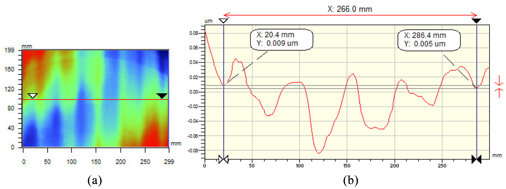
(a) Surface topography in low bolt preload and (b) extracted waviness of 53 mm.
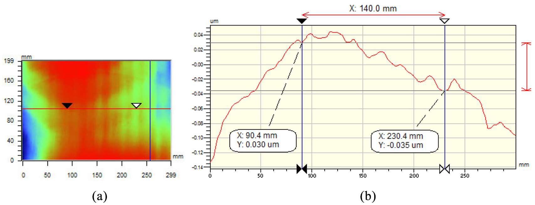
(a) Surface topography in high bolt preload and (b) extracted waviness of 23 mm.
By analyzing two machined surfaces, it can be found that when the stiffness of the joints is low, the medium-frequency waviness appears along the cutting direction. The wavelength is 53.2 mm for the total length of five waves is 266.0 mm in Figure 9(b). Its frequency is equivalent to 257.1 Hz, which is consistent with the fifth mode of the modal test with the error of 4.1%. Taking the vibration modes into account, it demonstrates that the fifth mode is the most sensitive one to the processing. In the case of high stiffness, the surface is no longer marked with the medium-frequency waviness of about 50 mm as exhibited in Figure 10. The newly appeared waviness of 23.3 mm are mainly generated by the modal vibration of the spindle. 17 Apparently, the natural frequency of the fifth mode increased and the vibration amplitude decreased by increasing the stiffness, so that the medium frequency waviness of about 50 mm disappeared.
The results indicate that the waviness of about 50 mm on the machined surface was motivated by the modal vibration of the machine tool in low stiffness. By increasing the stiffness of the joints, the dynamic performance of the entire machine tool can be greatly improved and the surface quality of workpiece are further improved as well.
Modal optimization of the whole machine
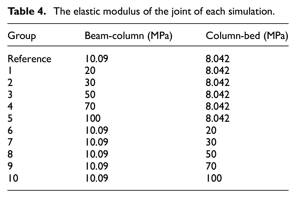
Taking the high-precision virtual material machine model as the object, the optimal combination of stiffness of the joint is found by changing the stiffness of the four key joints in the model. The specific simulation optimization design is shown in Table 4, in which the combined stiffness is represented in virtual material elastic modulus. The machine tool that has been modal analyzed is used as the reference group. The 1–5 groups of simulations keep the stiffness of column-bed joint unchanged, and gradually increase the beam-column joint stiffness. The 6–10 groups keep the stiffness of beam-column joint unchanged, and gradually increases the column-bed joint stiffness. The modal simulation of the machine tool is performed under 10 groups of different joint parameters, and the results are analyzed and compared.
The elastic modulus of the joint of each simulation.
The column-bed stiffness remains unchanged, and the natural frequencies of the machine tool vary with the stiffness of the beam-column joint as shown in Figure 11. When the beam-column stiffness is constant, the natural frequencies of the machine tool vary with the stiffness of the column-bed joint as shown in Figure 12. Apparently, the natural frequencies of each mode increase as the stiffness of the joint surface increases. In addition, the effect of increasing the stiffness of the column-bed joint is greater than increasing the stiffness of the beam-column joint.
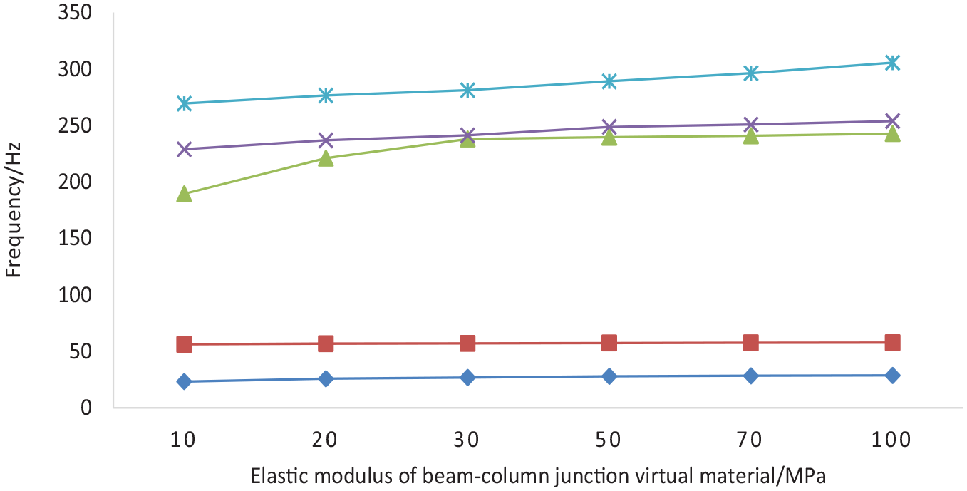
The natural frequency changes with the stiffness of the beam-column junction.
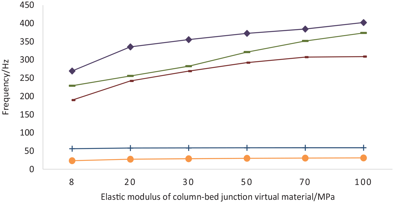
The natural frequency changes with the stiffness of the column-bed joint surface.
In practice, the stiffness of the joint can be increased by increasing the pre-tightening force of the bolt. Considering the strength limit of the bolt, the bolt pre-tightening force of the column-bed can be increased as much as possible within the bolt strength limit to increase the stiffness of the joint. The bolt pre-tightening force of the beam-column joint is increased from the original 30 N·m to 50 N·m, and the surface of the processed component no longer appears micro-wavelength about 50 mm.
Conclusion
Based on the simulations and the experiments, the dynamic performance of the flycutting machine tool was analyzed and the conclusions can be drawn as:
The stiffness and damping of four key joints were identified by the half-power-band method. And the material properties of the virtual material, like elastic modulus, Poisson ratio and density were deduced.
The modal analysis of the machine tool was carried out and was verified by the modal test. Results indicate that the fifth mode with the natural frequency of 269.38 Hz contributes most to the machining quality.
The flycutting experiments for the KDP crystals shows that the waviness of 53 mm appears under the low joint stiffness. By enhancing the stiffness of beam-column joints, the machined surface was refined significantly.
The bolt pre-tightening force of the beam-column joint is increased from the original 30 N·m to 50 N·m, and the surface of the processed component no longer has micro-wavelength about 50 mm.
Footnotes
Declaration of conflicting interests
The author(s) declared no potential conflicts of interest with respect to the research, authorship, and/or publication of this article.
Funding
The author(s) disclosed receipt of the following financial support for the research, authorship, and/or publication of this article: This work was supported by the Science Challenge Project [No. JCKY2016212A506-0504].