
Abstract
Press machine tools are often used in important industrial establishments, such as automobiles, aerospace, and aviation; these machine tools must be produced with high precision. Therefore, studies related to improving press tools and enhancing their precision are being conducted. In this study, a press machine tool based on the Stephenson II mechanism is proposed. Compared to that of conventional crank presses, this mechanism increases the slider balance using a ternary link and unique connecting rods. Thus, the slider precision can be improved with a small addition to the mechanism, and load transmission can be ensured in a balanced manner. To test the contribution of the mechanism, dynamic analysis is performed using the kinetostatic method, and the dynamic data of the mechanism are obtained. Subsequently, a press machine prototype is designed and manufactured. The experimental results are verified against the theoretical results, confirming that the proposed press machine tool based on the Stephenson II mechanism has better characteristics than those of the conventional press machine owing to the favorable distribution of forces on the slide and lower reaction to the slide guides.
Keywords
Introduction
Mechanical presses are extensively utilized in metal forming processes. Various types of linkage mechanisms have been proposed to meet the load and stroke characteristics of a particular metal forming process. During metal forming operations, the deep drawing process requires a gradual and extended stroke of the ram, while the shearing process requires a short stroke of the slide.1,2
The types of mechanical press available for stamping and forming operations vary according to the slide motion. 3 A conventional crank press operates based on a slider-crank mechanism, designed for stamping various parts, and can generate a sinusoidal slide motion.4–6 During the operation of a conventional crank press, substantial heavy dynamic loads occur on the mechanism parts when it is turned on. These loads are related to the crank press operational features, including sudden, almost immediate stops with shock cyclic loads. Therefore, the choice of mechanism structure of the crank press is crucial for decreasing the dynamic load during operation.7,8
Stamping accuracy is an important parameter of a crank press. The stamping accuracy of a crank press generally depends on two factors, that is, the inclination of the slide under the influence of an eccentric application of the deforming force and the total linear elastic deformation of the construction units of the press and the stamps under the load, which depends on the rigidity of the press structure and stamps.3–6,9
Various studies related to the design, kinematic modeling, dynamic modeling, and analysis of crank press mechanisms have been reported in the literature.
Erkaya and Uzmay10,11 performed kinematic and dynamic analyses of a modified slider-crank mechanism. The mechanism had an additional eccentric link between the connecting rod and crank. Anis 12 performed kinematic and dynamic analyses on a slider-crank mechanism using the Adams software with mechanism inertias. Wu et al. 13 studied a double crank press mechanism. They mathematically modeled the mechanism to evaluate the contact forces in a 3D translational joint with clearance. For the finite element analysis, ANSYS/LS-DYNA was used to prove the accuracy of the proposed model. Li et al.14–16 studied on the hybrid mechanisms of seven-bar and nine-bar press mechanisms for deep drawing applications. They presented kinematic and dynamic modeling and an analysis of these mechanisms. The Lagrangian method was used for dynamic models, wherein the fourth-order Runge Kutta method was preferred for integration. Kütük et al. 17 optimized an industrial seven-bar hybrid press mechanism for a deep drawing study using a genetic algorithm. They also presented a dynamic analysis using the kinetostatic method.
Abdullah and Telegin 18 studied a dynamic model and its mathematical description of a central slider crank mechanism for a crank press. The clearances at the joints of the mechanism and eccentricity were considered. Liu et al. 19 presented a kinematic and dynamic analysis of a slider-crank mechanism. The dynamic analysis was modeled using static equilibrium (kinetostatic approach). They also built the MATLAB-Simulink model. Jun 20 performed the basic theory of the mechanical dynamics method and kinetostatic analysis to obtain the numerical solutions of the slider-crank mechanism. Khemili and Romdhane 21 were interested in the dynamic behavior of a planar flexible slider-crank mechanism with clearance. They designed a model using the Adams® based impact-function, and manufactured and presented an experimental setup. Choi et al. 22 optimized the eccentric mechanism of a linear guide press based on a nonlinear search method. They modeled an objective function to satisfy the specified conditions of the forming processes. Chen et al. 23 established a dynamic model for the main transmission system of a high-speed precision crank press using Adams®. The mechanism included a crank and two connecting rods.
Cheng et al. 24 designed a double-axis crank servo press system. The slider was adjusted using a multi-axis servo system. The mechanism was designed using two servo motors, two crank shafts, and four connecting rods for slider precision. They also presented the experimental results. Qingyu et al. 25 studied the optimization and motion planning of a heavy loading eccentric servo press. Kaya26,27 improved the sheet metal forming of Al and Mg alloy materials. Warm forming experiments were conducted using a 110 ton servo press. A load cell was used to observe the punch load. The models were developed by calculating the heat transfer coefficients. The computational model was validated using the experimental results. They also studied the non-isothermal warm deep drawing of stainless steel and verified the finite element (FE) predictions. Halicioglu et al. 28 studied the dynamic modeling and experimental implantation of a servo crank press. They used the Lagrangian method for dynamic modeling. A manufactured servo press prototype was operated and the experimental results were found to be in good agreement. Halicioglu et al. 29 also developed a soft motion scenario that was applied to enhance the forming quality. This press system with optimized motion exhibited good tracking precision for the slider. The optimized motion provided a better surface quality at higher speeds. Gao et al. 30 manufactured a servo press with a toggle booster mechanism driven by a tubular permanent magnet linear motor. They modeled the dynamics of the mechanism and analyzed them. Subsequently, they presented the theoretical and experimental results together.
In addition to metal forming and the mechanisms, a model with the maximum undeformed chip thickness was proposed by Zhang et al. 31 which was in good agreement with the experimental results for brittle materials.32,33 They also presented an approach of single grain scratching performed on a developed grinder, in which the speed was three to six orders of magnitude higher than that in nanoscratching. 34 The force, stress, depth of cut, and size of plastic deformation were calculated on the onset of cutting and brittle-to-ductile transition. 35 With the breakthrough in these mechanisms, new manufacturing tools and methods have been developed.36,37 These explorations are a landmark contribution to conventional manufacturing because it is difficult to develop high-performance surfaces using traditional manufacturing techniques. 38
It has been reported in the literature that the precision and slider balance of a crank press machine can be increased by using servo motors, more than one crank with more than one motor or complex mechanisms. These applications increase the press manufacturing cost while improving slider precision. However, an increase in cost is undesirable. Therefore, Jomartov et al. 39 proposed the use of a Stephenson II six-bar linkage mechanism to increase the precision of crank presses. A new crank press was synthesized based on the Stephenson II six-bar linkage. This crank press operates based on a simpler mechanism and can be manufactured without increasing the press manufacturing cost. To test the functionality and identify the advantages of the new crank press, it is necessary to dynamically analyze the Stephenson II linkage and perform experimental validation. Previous studies have shown that while MATLAB and Adams software are used as packet programs, Lagrangian and kinetostatic analyses are often used for dynamic analyses.
In this study, the six-bar Stephenson II linkage mechanism, including a ternary additional link with two connecting rods for precision, was dynamically analyzed using the kinetostatic method. A press prototype based on the Stephenson II mechanism was manufactured to test the functionality and identify the advantages of conducting experimental research. It is necessary to develop a method for the experimental research of a press machine based on the Stephenson II mechanism, which is based on modern digital devices with information processing algorithms, and visualization of the measured signals.
Mechanism definition
Figure 1(a) depicts the Stephenson II six-bar linkage mechanism. In contrast to that of the conventional crank press (Figure 1(b)), this mechanism includes a ternary link between the crank and connecting rod. By adding the ternary link, the slide can be balanced with two equal connecting rods.
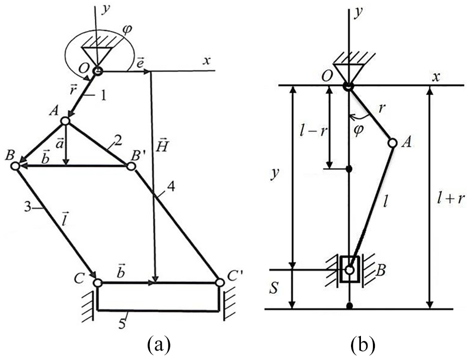
Schematics of mechanisms: (a) Stephenson II press mechanism (r: crank length, a: ABB' triangle height, l: parallel connecting rods length, φ: the angle of a crank, ψ: angle of two connecting rods, H: linear coordinate of slider, e: slider eccentricity, andb: distance between joint C and slider center along an axis Ox), (b) Conventional crank press mechanism (r: crank length, l: connecting rod length, φ: the angle of a crank, S: stroke length)
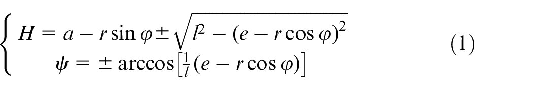
The kinematic position of the mechanism can be analyzed using equation (1).
39
Kinetostatic analysis of Stephenson II six-bar linkage
The vector method for solving an important problem related to the dynamic analysis of mechanisms, called kinetostatic analysis, was considered.
40
Using this method, the external force, mass, and inertia effect during the movement of the mechanism can be balanced by the reaction forces. Kinetostatic analysis is practically significant when selecting electric motors and calculating kinematic pairs’ bearings. For instance, given the constant angular velocity of a driving member (
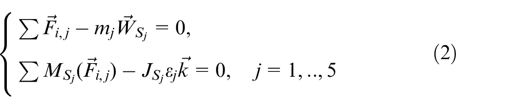
Figure 2 depicts the equilibrium forces of the Stephenson mechanism. Slider eccentricity of e is equal to zero since the mechanism is considered a central mechanism in this study. Based on D’Alembert’s principle, the equilibrium equations of the five links can be written as follows:
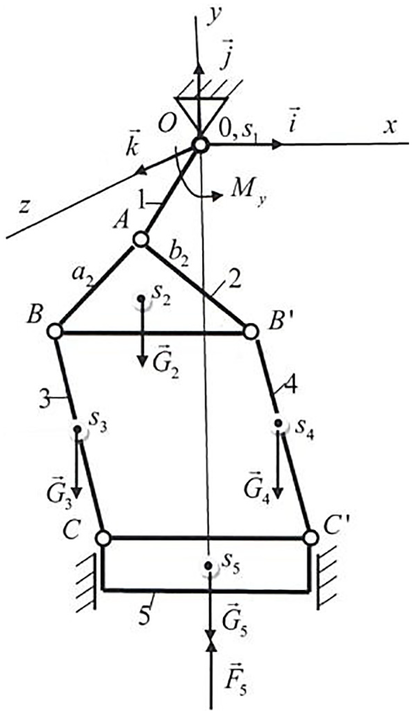
Load representation of Stephenson II six-bar linkage mechanism.
Here,

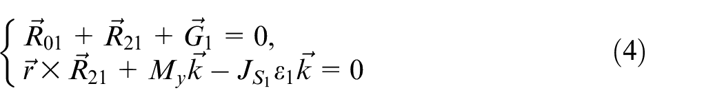
When equation (2) is used to determine the equilibrium equation for each link, we can derive further equations. For driving link 1, assuming that it is statically balanced (Figure 3(a)), we obtain equation (4).
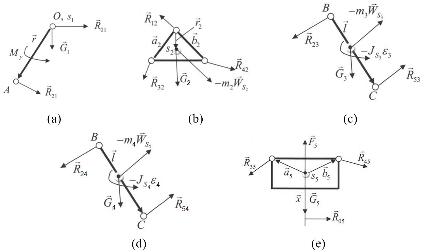
Forces acting on: (a) link 1, (b) link 2, (c) link 3, (d) link 4, and (e) slide 5.
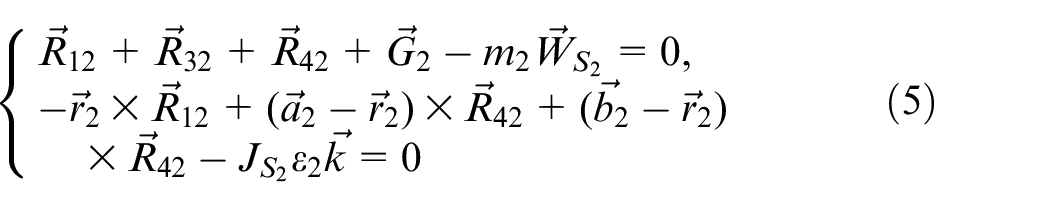
For link 2, the static balance (Figure 3(b)) can be determined using equation (5).
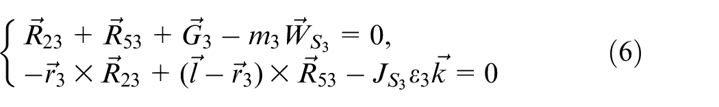
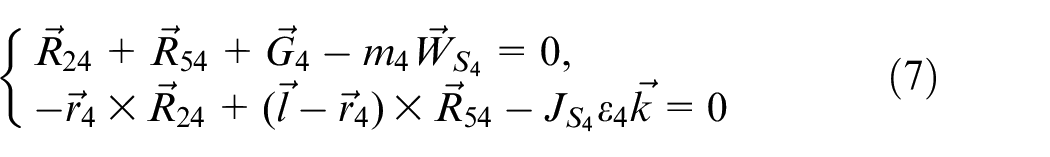
For links 3 and 4 (Figure 3(c) and (d)), equations (6) and (7) can be written as follows:
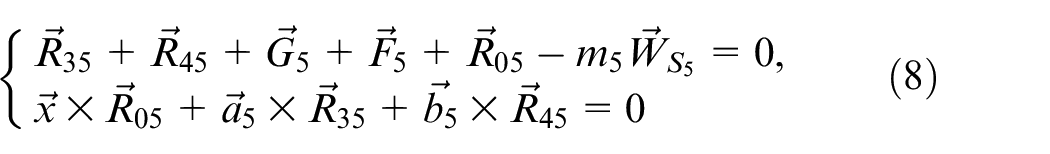
For slide 5 (Figure 3(e)), the equilibrium conditions can be written as shown in equation (8).
In these equations, the basis vector of the coordinate axis

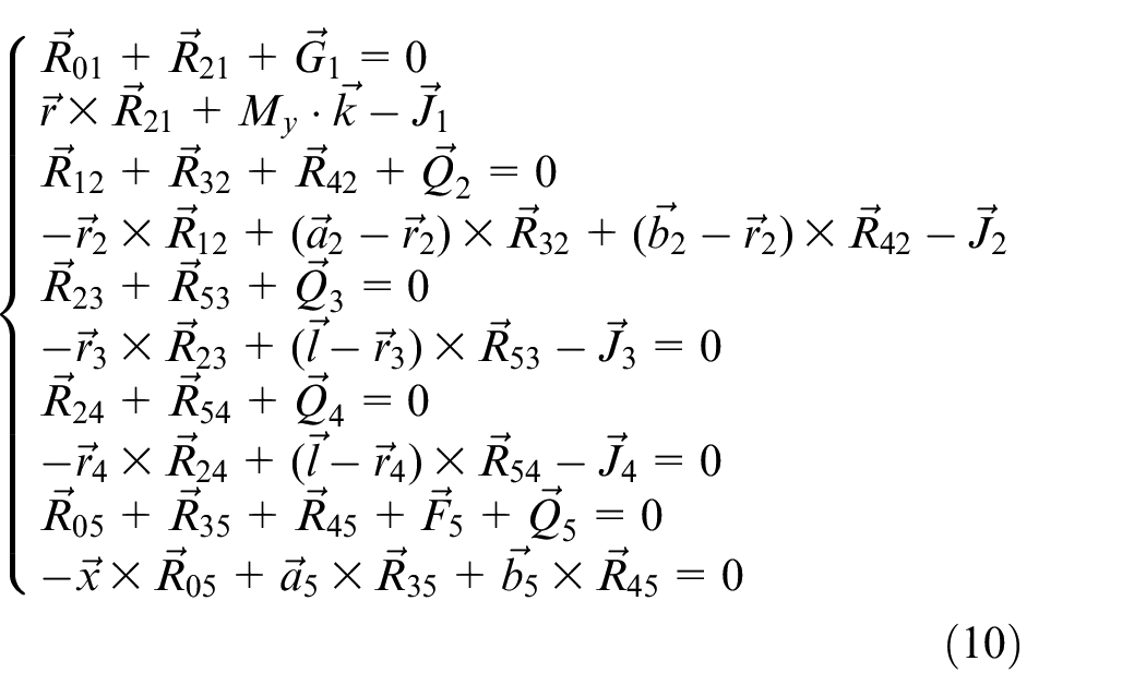
Accordingly, the equilibrium equation of the mechanism system can be written as shown in equation (10).
If
After vectorially multiplying the third equation of the system by

Similar steps were applied for the fifth and sixth equations and seventh and eighth equations of the system in equation (10). Then, equations (13) and (14) can be obtained.


The relations can be introduced as given in equation (15).

Then, equations (12)–(14) can be written in the following form:
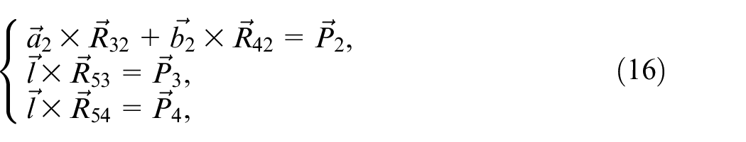
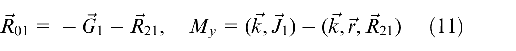
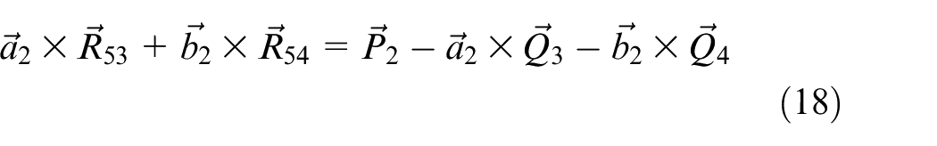
From the system equation (10), we can also derive

By substituting equation (17) into the first equation of equation (16), equation (18) can be obtained.
The last two equations in equation (16) can be written as:
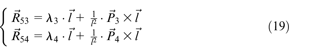
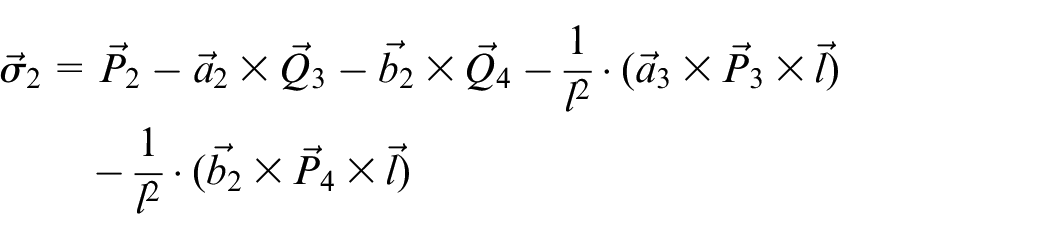
By substituting equation (19) into equation (18), equation (20) can be obtained.

where
After performing scalar multiplication on the second last equation of the system, that is, equation (10) multiplied by

Alternatively, by considering equation (19), equation (22) can be obtained.

Here,
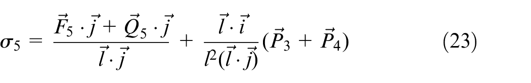
By solving equations (20)–(22),
Using equation (19) and
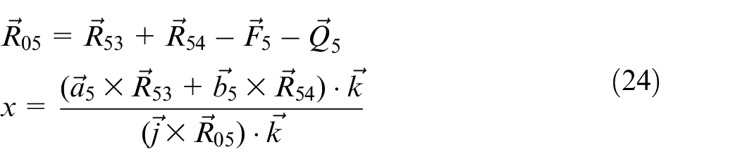
Next,
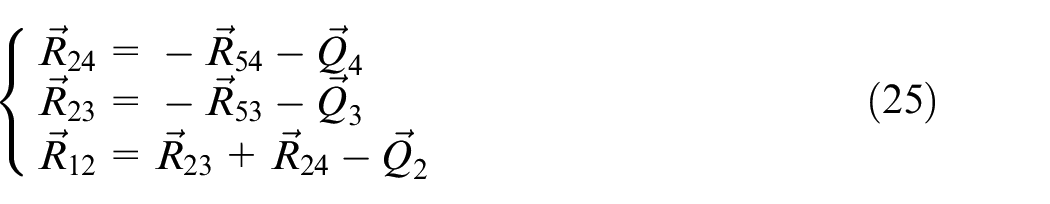
Thus, the problem of kinetostatic analysis was solved using the vector method. According to the obtained formulas, the balance moment and reactions in kinematic pairs can be determined for the entire part of the movement,
Kinetostatic analysis of a prototype crank press based on Stephenson II linkage
Test calculations were performed with the following dimensions of the actuator links of a prototype crank press based on Stephenson II linkage: r = 0.04 m, l = 0.185 m, a = 0.06 m, and b = 0.065 m. The law of motion of the crank is given in the form of
The load force,
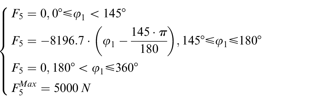
Figure 4(a) depicts a graph of the load force,
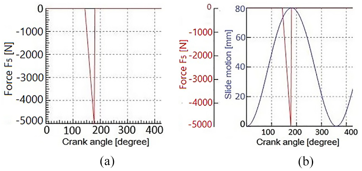
Graphs: (a) load force
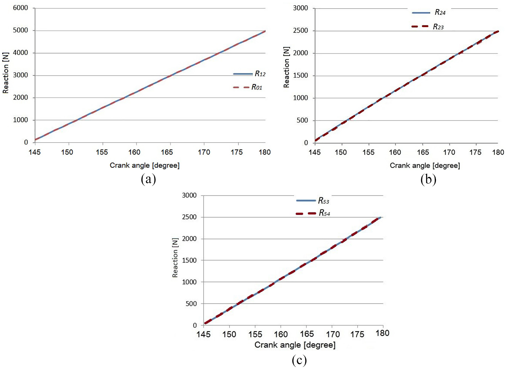
Absolute values of reactions: (a)
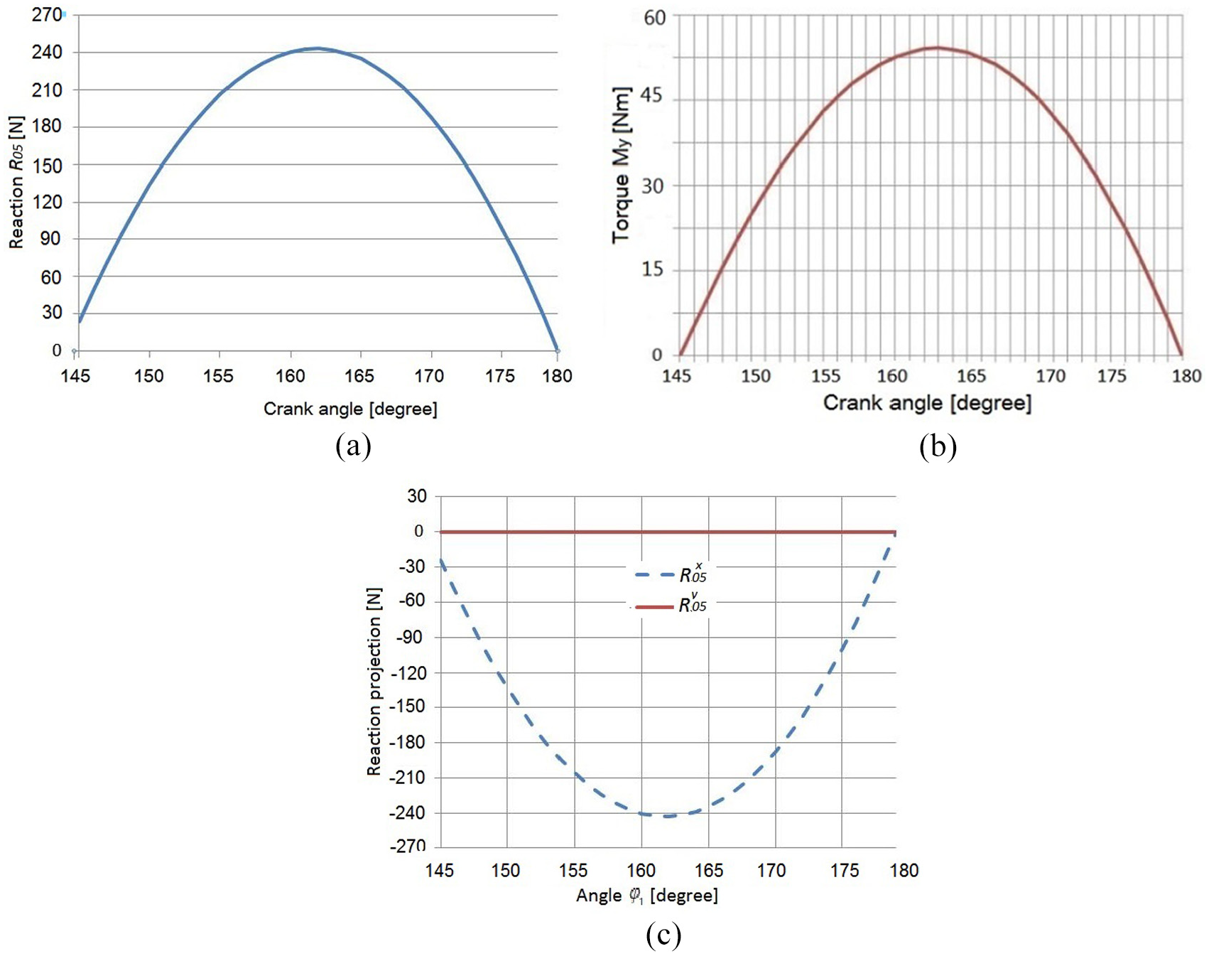
Graphs: (a) absolute values of reaction
Figure 6(c) shows graphs
Figure 5(a) indicates that the reaction
At a given load on the slide, that is,
From Figure 7, 41 the component of force F acting on the slide guides of a conventional press can be determined.

where β denotes the angle defining the position of the connecting rod relative to the vertical passing through the center of the crank shaft. In practice, based on the accepted values of the crank and connecting rod dimensions, the maximum value of angle β during stamping should not exceed approximately 8°–10°.
41
From equation (26) with F = 5000 N,
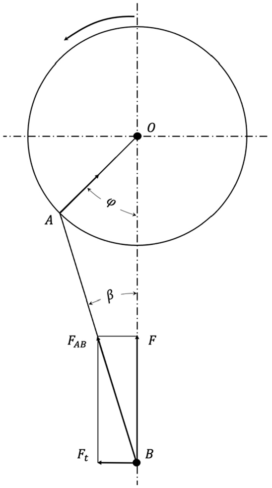
Forces on a conventional press.
Experimental research for crank press prototype based on Stephenson II linkage
A prototype of a crank press based on the Stephenson II mechanism was manufactured. Figure 8 illustrates a general view of the manufactured prototype of a six-linkage crank press based on Stephenson II.
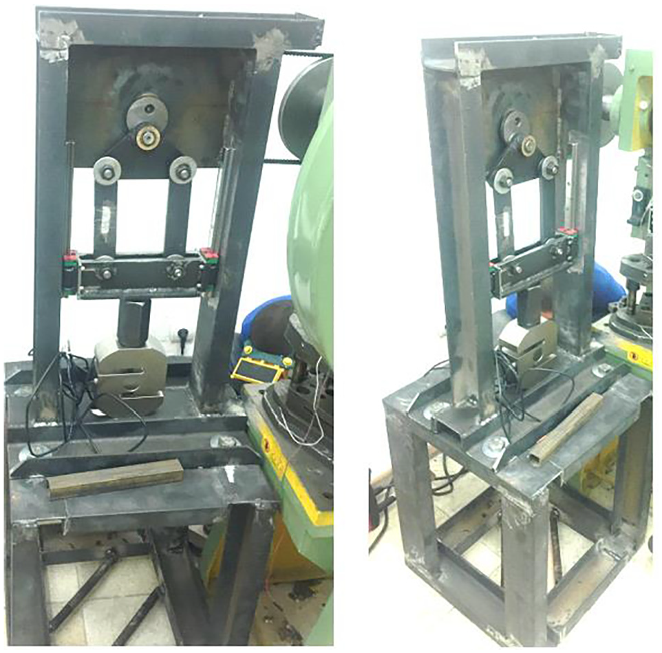
Prototype of a crank press based on Stephenson II six-bar linkage.
The experimental setup of the prototype crank press based on the Stephenson II mechanism (Figure 9) was built on the digital devices of the ZETSENSOR® series 42 with a CAN® interface.
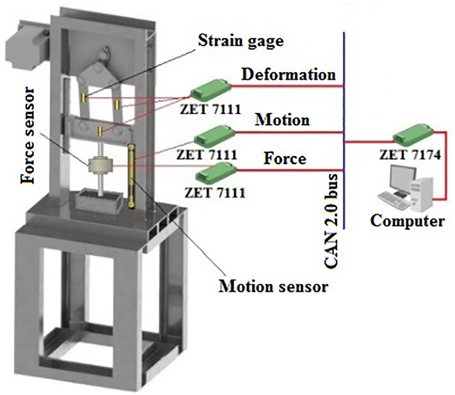
Experimental setup of the press based on Stephenson II mechanism.
The system enables the measurement of the following parameters: motion of slide, force acting on the slide, and stresses on the links of the press.
A digital force sensor was used to measure the force of the crank press. The digital force transducer contained a UU strain gage and a ZET 7111 measuring module. 6 The linear motion of the slide was determined using a digital motion transducer. The digital motion sensor comprised an RL inductive sensor and a ZET 7111-L measuring module. 6 Foil strain gages were used to measure the deformations and stresses on the links of the Stephenson II mechanism.
The motion sensor and force sensor were installed directly on the press slide; they transmitted signals proportional to the relative movement of the slide and the force exerted by the slide on the die. Strain gages were mounted on the press links; it is necessary to determine the stresses arising during operation. These signals were processed by ZET 7111 measuring modules, which transmit the measured values via the CAN 2.0 bus to the ZET 7174 interface converter and then to the computer via USB 2.0.
Experimental research results
The experiment was performed on a crank press prototype based on the Stephenson II mechanism, with the following parameters: electric motor power = 1.4 kW and constant crank speed = 95.5 rpm (10 rad/s). The applied experimental setup is presented on the prototype, as depicted in Figure 10(a).
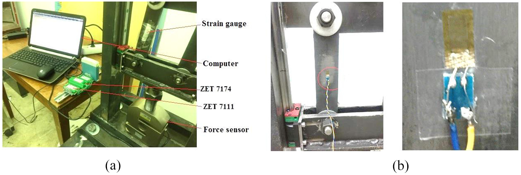
(a) Prototype of crank press based on Stephenson II linkage and (b) fragment of the strain gage sticker on the connecting rod.
In the course of experimental research, a hole with a diameter of 5 mm was cut by a stamp in a steel sheet with a thickness of 0.8 mm. The punching operation was performed by a single press stroke. Figure 10(b) depicts the connecting rod of the press with a mounted strain gage to determine the stress. The cross-sectional dimension of the connecting rod at the strain gage sticker was 4.2 × 1.0 cm2.
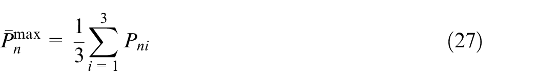
The stress was measured three times in the cross-section of the connecting rod when punching a hole with a diameter of 5 mm in a steel sheet with a thickness of 0.8 mm; accordingly, the following maximum values were obtained: Pn1 = 6.796 MPa, Pn2 = 6.803 MPa, and Pn3 = 6.653 MPa. The average value of the maximum stress,
The mean square deviation, σ, is determined using equation (28).
From equations (27) and (28),
Figure 11 shows an experimental graph of the average stress,
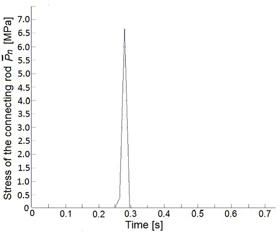
Experimental graph of the average stress,
To evaluate the calculated force,
From experimental research, it was found that in the absence of eccentricity, the nominal punching force was uniformly distributed on the connecting rods.
To determine the reaction on the slide guides of the press, a strain gage was mounted on the slide, as shown in Figure 12(a). The strain gage was perpendicular to the direction of motion. The cross-sectional size of the slide at the measurement point was
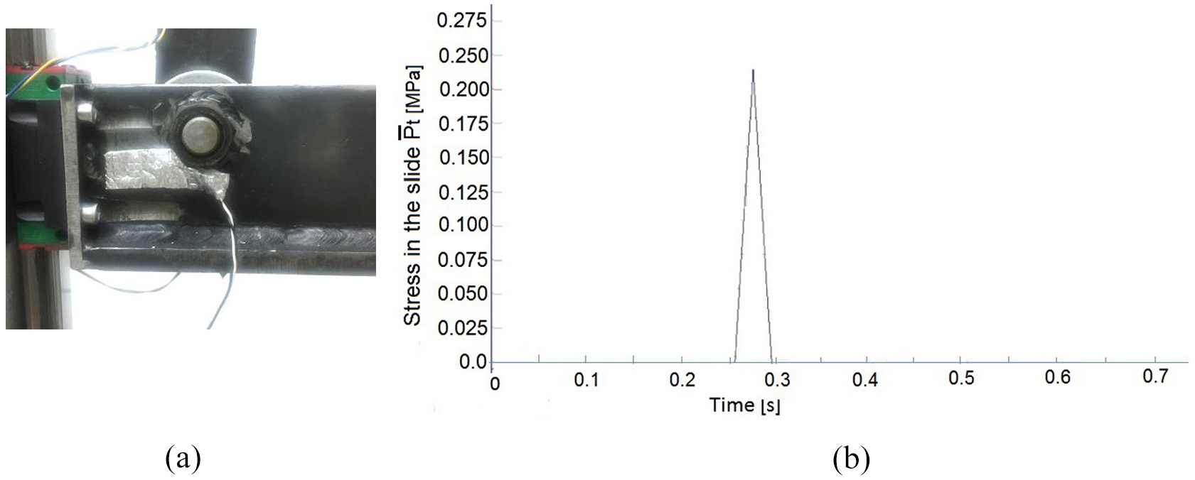
(a) Fragment of the strain gage sticker on the slide and (b) experimental graph of the average stress
We measured the stress three times in the cross-section of the slide when punching a hole with a diameter of 5 mm in a steel sheet with a thickness of 0.8 mm, and obtained the following maximum values: Pt1 = 0.229 MPa, Pt2 = 0.251 MPa, and Pt3 = 0.296 MPa. The average value of the maximum stress,
Figure 12(b) shows an experimental graph of the average stress,
The maximum stress during punching was observed to be
In comparison to the maximum force on the slide,
We measured the crank torque three times, whose graphs are shown in Figure 13; here, the solid blue line denotes the theoretical torque. Experimental torques are represented by the brown dashed, red dotted, and green starry lines. As evident from Figure 13, the theoretical results are significantly consistent with the experimental results.
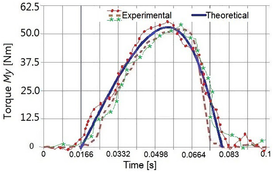
Experimental and theoretical results of torque
Moreover, experimental research confirmed that the crank press based on Stephenson II linkage exhibits better characteristics in comparison to those of conventional presses owing to the favorable distribution of forces on the slide, resulting in lower reactions to the slide guides.
Conclusion
Metal forming is an important application in several industries that requires production precision. By improving the metal forming production quality, a new press machine based on the Stephenson II mechanism was considered in this study. Kinetostatic analysis was performed for dynamic analysis. Accordingly, this machine was manufactured and experiments were conducted for its evaluation. The theoretical results were validated by the experimental results. Moreover, an experimental research method was developed for the press machine based on the Stephenson II mechanism; it is based on the digital devices of the ZETSENSOR series with a CAN interface. The information processing algorithm and visualization of the measured signals were performed using the ZETLAB SENSOR software and its subprograms. Investigations on an experimental industrial model of the proposed press machine demonstrated that the maximum reaction from the slide rails of the press was 4.91% of the maximum force on the slide.
Footnotes
Declaration of conflicting interests
The author(s) declared no potential conflicts of interest with respect to the research, authorship, and/or publication of this article.
Funding
The author(s) disclosed receipt of the following financial support for the research, authorship, and/or publication of this article: This research was funded by the Science Committee of the Ministry of Education and Science of the Republic of Kazakhstan (Grant No.: AP09259339).