
Abstract
Sheet metal or monolithic thin structured components with complex freeform geometries are used in wide range of applications in aerospace, marine and automobile sectors. Fabrication of such complicated geometries and profiles generally requires complex manufacturing setup (dies, jigs and punches) resulting in process inflexibility, in addition to huge tooling and equipment costs. In the present work, a novel process ‘single point incremental bending’ (SPIB) is proposed. In principle, it is similar to single point incremental forming process. SPIB is a die less bending operation where a solid hemispherical shaped single point tool is used to locally bend the sheet metal to a desired shape incrementally using a computer numeric controlled setup or certain robotic platforms. In addition to that, an experimental and finite element analysis based numerical study on the bending load patterns and trends in single point incremental sheet metal bending has been presented. Detailed investigation of various commercial sheet metals and various parametric effects on bending load is also performed. The influence of sheet material, material anisotropy and four major process parameters – sheet thickness, tool diameter, incremental bending angle and sheet height to length ratio on the bending loads is investigated.
Introduction
Fabrication of sheet metal and thin components having complicated geometries and profiles, at a reasonable manufacturing cost, without compromising the quality is a huge challenge for the researchers and engineers. Generalised and conventional approach for the fabrication of such components include (i) designing freeform components; (ii) design and development of component specific dedicated die and punch set; (iii) fabrication of components. Moreover, employing conventional manufacturing techniques and approaches for such applications result in process inflexibility and higher equipment costs.
Sheet metal working is known to the man kind since ancient ages. The introduction of external powered machinery during the industrial revolution has led to development of conventional machined presses for sheet metal bending. Machine tool generally consists of a single set or multiple punches and dies of various shapes and sizes. Based on the final sheet geometry and sheet material, the punch displacements, tooling sequence and tooling loads are defined. Use of computer aided techniques in sheet metal bending has revolutionised the process. Generative sheet metal bending process and its various aspects based upon the CAD design using conventional robotic press brakes and dies were explored. Use of computers in part representation and part classification by Duflou et al. 1 has improved the efficiency of sheet metal bending process planning activities. Development of robotic assisted bending and robot supported part manipulation systems with conventional press brake bending arrangement greatly enhancing the quality and productivity of the process. Incremental in-plane bending or step bending introduced by Jin et al. 2 is a recent addition to the sheet metal bending enhancing the bendability in conjunction with reduced bending load. Kuboki et al. 3 applied the same method in increasing the bendability of wires and tubes. Zhang et al. 4 introduced an automated incremental bending machine in which sheet metal is supported by movable holders and punch movement is in accordance with the given trajectory. However, all these improvements are only limited to the partly flexible, part oriented conventional sheet metal bending process using dedicated dies and presses.
Introduction of computer aided and control manufacturing in addition to the above mentioned instances in conventional sheet metal forming, has been a key driving force in development of a flexible sheet metal forming process in the form of incremental forming. The process of backward bulge incremental forming using a single point hemispherical tool was first introduced by Matsubara. 5 The process mechanics of incremental forming have been subsequently well defined experimentally by Adams and Jeswiet 6 and analytically in terms of various forces generated and stresses developed in the process by Martins et al. 7 The process has been well defined in terms of sheet material, tooling, strategies, methodologies, 8 accuracy, 9 formability10,11 and forming loads. 12 Therefore, this provides an opportunity to explore the same in conventional sheet metal bending, making it more flexible, through a tool path controlled incremental bending employing simpler tooling on widely used and accepted three-axis CNC machining or certain robotic platforms.
Single point incremental bending process (SPIB) is introduced as a novel, possibly flexible and cost effective solution for generation of complex shapes and profiles of desired sizes and orientations on the sheet metal components, without employing additional or dedicated machinery. Single point incremental bending is a die-less forming processes where a solid hemispherical shaped single point tool is used to bend a thin structure or sheet metal to a desired shape incrementally according to a given tool path on a commonly employed three axis computer numeric controlled (CNC) milling machine or a robotic setup. Figure 1 shows the schematic of single point incremental bending depicting its dimensional attributes and major process parameters viz. sheet thickness (t); exposed sheet area to be bent (He × L); maximum bent angle (α); incremental bent angle in each pass (Δα) resulting from tool movement in Δx and Δz Cartesian directions; bending feed rates (fb) in Y Cartesian direction; and tool diameter (d).
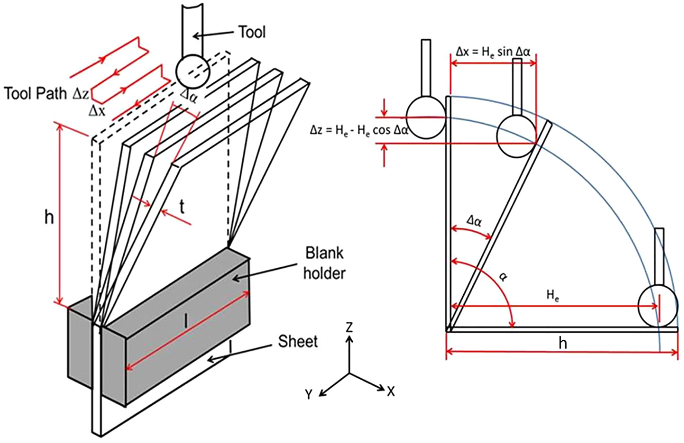
Schematic of single point incremental bending.
Smith et al. 13 introduced flexible tool path controlled incremental bending process in the process called ‘Deformation Machining’ in conjunction with thin structure machining. The work presented was primarily for uniform bending along the length of sheet with uniform height (h) that is, parallel bending with equal amount of increments in each pass. Subsequently, comparison of dimensional repeatability and fatigue life of incremental ‘uniformly’ bent sheet metal with conventional bending of similar sheet metal components was done by Agrawal et al. 14 The results indicated that dimensional repeatability for both the processes almost indistinguishable. Considerable improved fatigue life of incrementally bent in comparison to conventionally bent components was noticed. A comparative study of bending forces in single point incremental bending and conventional bending for the same material and geometry was done by Singh and Agrawal. 15 The study concluded that the maximum bending force is approximately 33% less in incremental bending in comparison to conventional bending.
The process of incremental bending is in its early stage of development and requires in-depth exploration to be competitive in the industry. This work is an initial attempt in determining the feasibility of the process and validating the same through experimentations and numerical simulations. For this, understanding of the process mechanics and defining of critical process parameters is of utmost importance. Forces required in incremental bending has a direct influence on design of tooling and fixtures, and selection of machinery required. This work presents a comprehensive experimental and numerical study regarding bending force trends incurred during uniform incremental bending with uniform height (h) of the sheet metal. In addition, the influence of sheet material, material anisotropy and four major process parameters – sheet thickness, tool diameter, incremental bending angle and sheet height to length ratio on the bending loads has been presented. Moreover, non-uniform incremental bending with non-uniform height (h) across the length of sheet by aptly designing and fabricating a sheet metal holding fixture for the process was carried out. Also, a successful attempt was made producing multiple incremental bends in the sheets.
Methodology
Experimental methodology
Experiments have been carried out on a three axis CNC vertical milling machine (Make: BFW, Model: VF 30 CNC VS). The sheet metal samples of different thicknesses and heights were clamped on Kistler 9257B six-component force dynamometer, a table type force sensor, which was mounted on the machine table (Figure 2). The dynamometer was connected to Kistler 5070 8-channel charge amplifier. The amplifier amplifies the electrical signals generated during force exerted on the component by the tool and real time force data in three Cartesian directions X, Y and Z of the machine during incremental bending was recorded on a computer based data acquisition system. The spherical tool (High Speed Steel) used for incremental bending was mounted on the spindle of the machine.
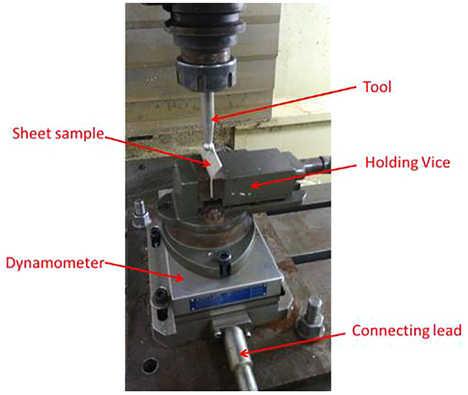
Experimental setup for the force measurement (Sample of AA 6063 T6, t = 1 mm, h/l = 0.4, Δα = 5°, d = 10 mm).
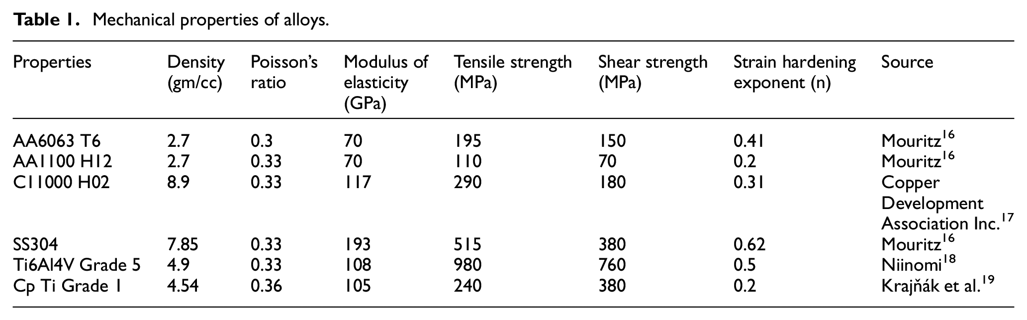
Table 1 depicts the mechanical properties of the six sheet metals alloys: commercial Aluminium alloy (AA 6063 T6), commercially pure Aluminium (AA 1100 H12), Copper alloy (C11000 H02), Steel (SS 304) Titanium alloy (Ti6 Al4 V) and commercially pure Titanium (Cp Ti Grade 1) were used in the present study. The selected materials cover diverse applications in automobiles, avionics, shipping and structures, corrosive environment and bio-medical engineering, along with a wide range of mechanical properties. Figure 3(a) and (b) represents the load-deflection results of the all the materials and material anisotropy of AA 6063 T6 respectively. The prior anisotropy of the rolled sheet metal was taken into account by bending parallel to the rolling direction and normal (perpendicular) to the rolling direction. The flexural strength was calculated from a three point bend testing according to ASTM E855-08 standards (Figure 4).
Mechanical properties of alloys.
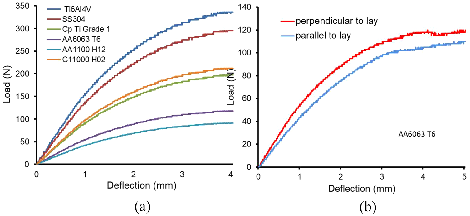
Load–deflection results of: (a) different materials and (b) material anisotropy in case of AA6063-T6.
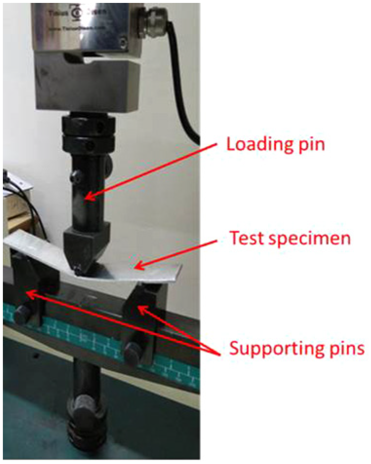
Three point bending test apparatus.
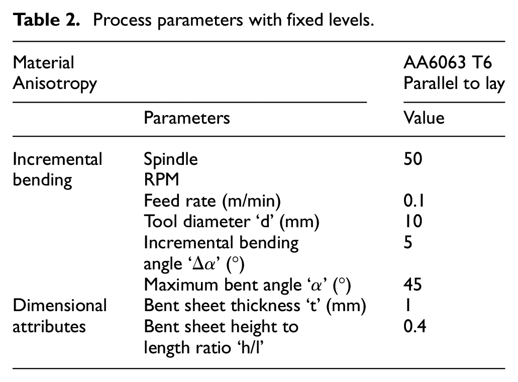
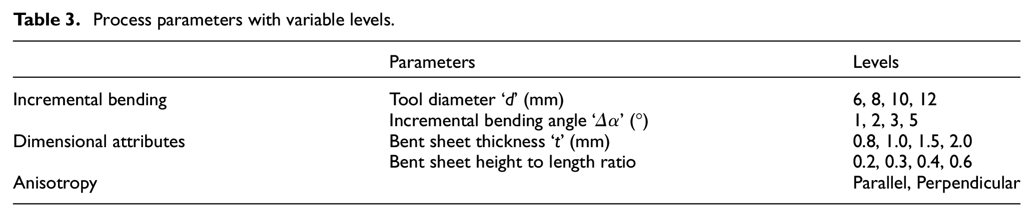
Table 2 depicts the fixed level of bending parameters and dimensional attributes of the sheet. Table 3 depicts the variable levels of bending parameters and dimensional attributes for which the bending load was measured. For example, the variation of bending load with change in incremental bending angle is obtained by keeping all the parameters constant to the level given in Table 2 except for the incremental bending angle levels.
Process parameters with fixed levels.
Process parameters with variable levels.
Numerical simulations
Incremental bending process has been simulated using Abaqus 6.13, a commercial finite element based software for bending forces induced at all process parameters and dimensional attributes corresponding with the experimental trials.
Material Model: The material model used in numerical simulation was Johnson-Cook (J-C) flow stress constitutive material model. J-C flow stress model is widely accepted and used as this model takes into account isotropic hardening and adiabatic heating of the material undergoing strains along the associated yield strength (equation (1)). The parametric constants of the constitute model for all the test materials are provided in Table 4.

Parametric constants of Johnson Cook model for the test materials.
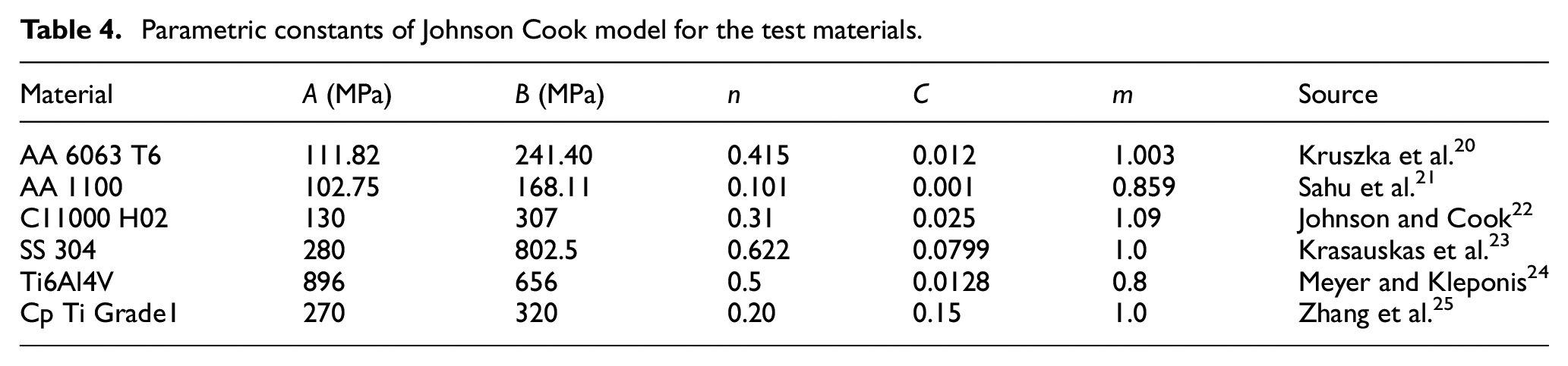
where εp is the effective plastic strain, Tm is the melting temperature, Tr is the room temperature and A, B, C, n, m are the model parameters. The single point hemispherical tool used in simulations was considered to be rigid.
Meshing: A total of 96,800 hexahedral elements with global size of 0.5 mm with were used for the analysis of sheet metal to be bent incrementally. Iterative mesh convergence on element size with less than 5% variation in results was conducted leading to the optimised size of element. Also, for a solid plate structure, mesh orientation studies at 0°/90°, 30° and 60° were performed. 26 The results in these iterations were similar, therefore mesh orientation of 0°/90° was selected.
Interaction: Surface interaction between single point tool and sheet metal was considered to be tangential with the tool is rigid and adiabatic, the frictional contact is described by Coulomb’s friction law with the constant coefficient of friction µ. The coefficient of friction was set to 0.3 for sliding friction between two metals under lubricating conditions.
Boundary conditions: Sheet metal end was fixed in all three directions (encastred) (Figure 5(a)). Rotational and translational degree of freedom was provided to the tool for corresponding tool path generated on CATIA V6 machining module. Incremental bending and tool retraction step was done in dynamic explicit module (Figure 5(b)).
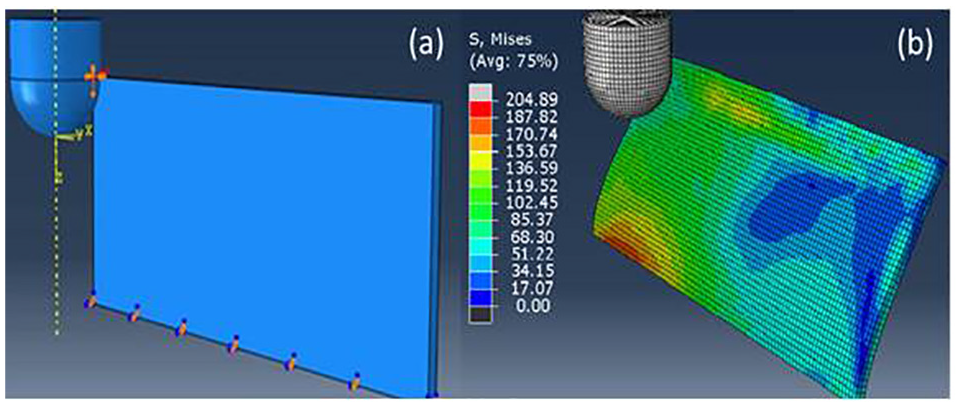
(a) Boundary conditions in incremental bending and (b) output field in the process simulations.
Results: The force evaluations were done by obtaining the reaction forces at a preset reference node on the tool.
Results and discussion
Force trends in incremental bending
Figure 6 depicts three force components in Cartesian system during incremental bending of the AA 6063 T6 sheet metal bent up to angle of 75°. A crest and trough is noticed with each increment for all three force components as the single point tool travels along the length of the sheet metal. Increased amount of bending load forms a crest as the tool passes through the centre of sheet along the length and a trough is noticed when the tool approaches ends of the sheet metal. The trends from the figure show that the maximum deforming force acts in X-direction (perpendicular to the axis of tool) till 45°. This is due to the greater tool movement in X Cartesian direction (ΔX = H e SinΔα) in comparison to Z Cartesian direction (ΔZ = H e −He CosΔα) for every constant increment (Δα). At bending angle 45° the magnitude of FX and FZ is same. Bending beyond 45°, FZ is the major contributor in the bending forces (along the axis of tool) as FX starts decreasing, due to greater tool movement in Z Cartesian in comparison to X Cartesian direction. The magnitude of FY is negligible in comparison to FX and FZ components and primarily depends upon the friction between the rotating tool and the wall surface. Another noticable trend is the increased amount of forces in all Cartesian directions with each increment. This is primarily due to the localised spring back and strain hardening of the sheet after the tool passes over it. So, in subsequent increment the tool has to bend more to achieve same amount of sheet deflection (Δα), therefore corresponding forces required to bend at certain incremental angle in subsequent pass increases in comparison to the previous pass. In addition to this, there shall be certain strain hardening of the sheet contributing to the increase bending load, with each passing increment. The force trends and magnitude obtained from numerical modelling using the finite element approach have been quite similar to the experimental one, simulating the same process parameters (Figure 7).
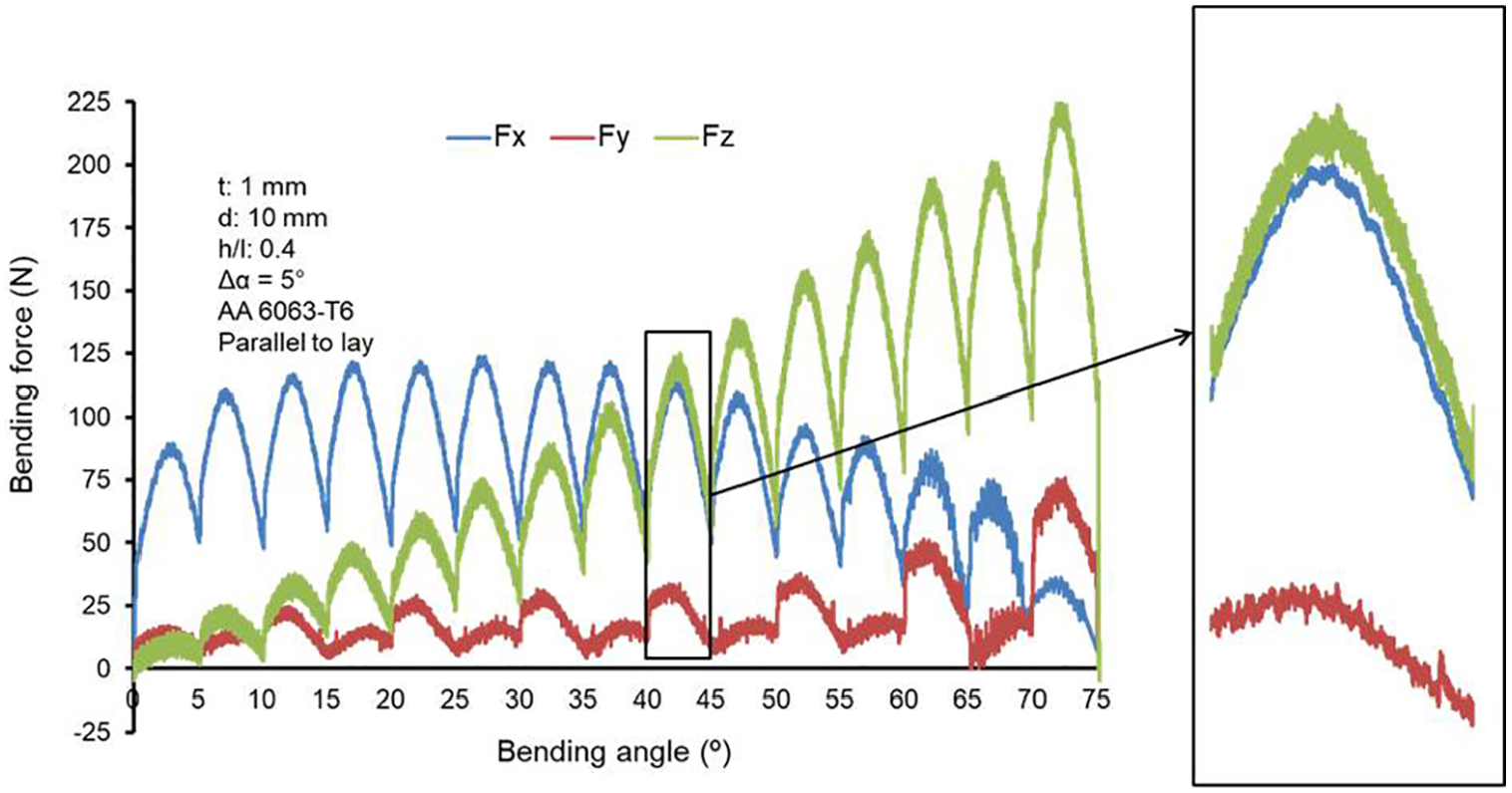
Experimental trends of three force components in DM incremental bending (FX, FY and FZ).
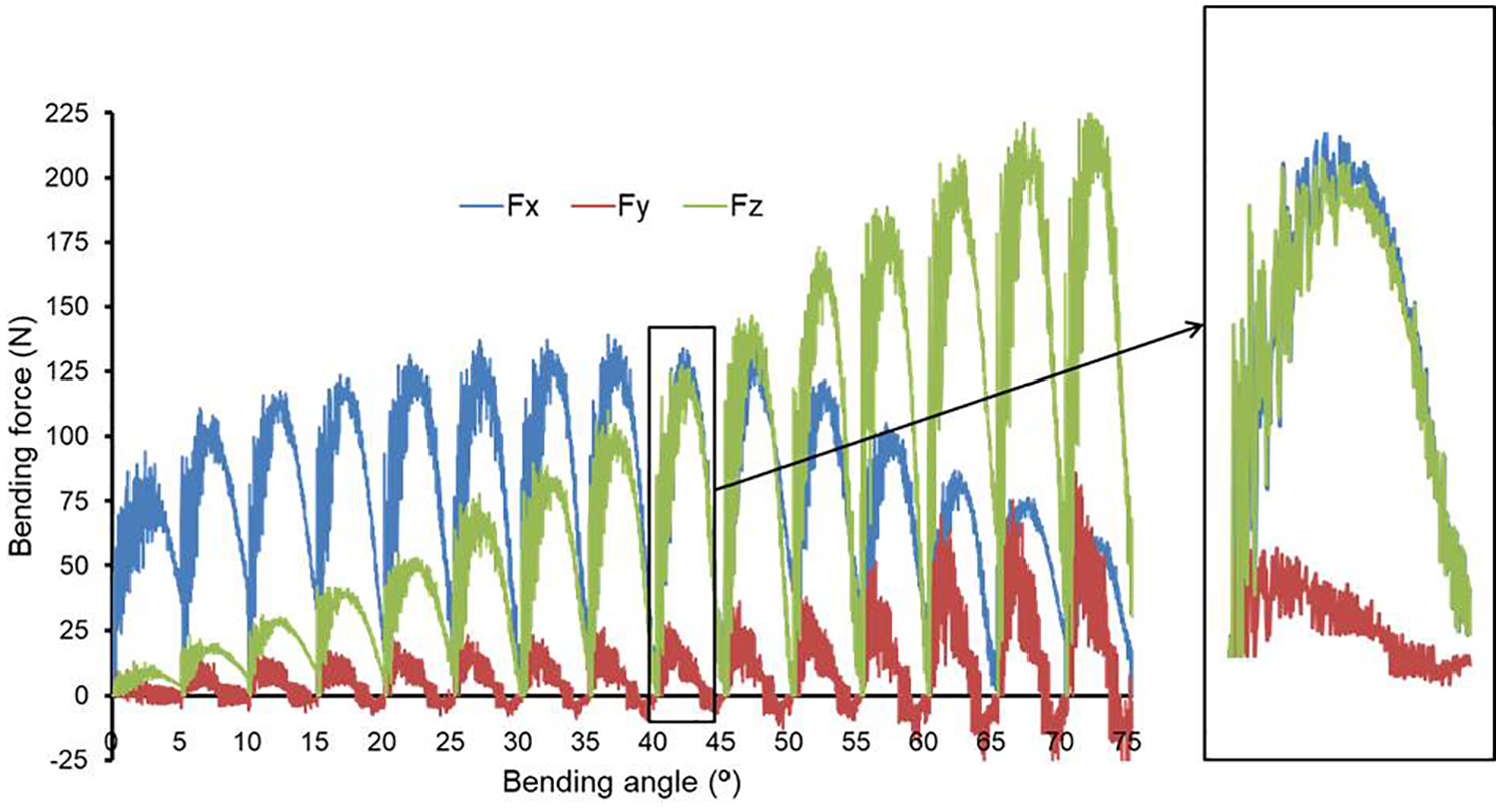
Numerical simulation trends of three force components in DM incremental bending (FX, FY and FZ).
Parametric effects on bending load/forces
Effect of individual parameters on average resultant force evolved during incremental bending process was studied.

where, Fresultant is the resultant force, Fx is force component in X direction, Fy is force component in Y direction, Fz is force component in Z direction. The resultant force used in the current study was taken from the three force components between 40° and 45° increment step, highlighted in Figures 6 and 7. This incremental step was chosen because at this increment the three Cartesian forces equal and averages out. The average of resultant forces used in the evaluations were taken from three experimental readings at each level of every parameter.
Influence of sheet material
The average resultant bending forces vary considerably in experimental results with each material as shown in Figure 8. The average resultant bending force for AA1100 H12, AA6063 T6, Cp Ti Grade 2, C11000 H02, SS304 and Ti6Al4V are 106.14, 135.92, 204.59, 212.60, 315.10 and 372.9 N respectively for the set of parameters given in Table 2. The trend is attributed to the inherent tensile strengths of different materials.
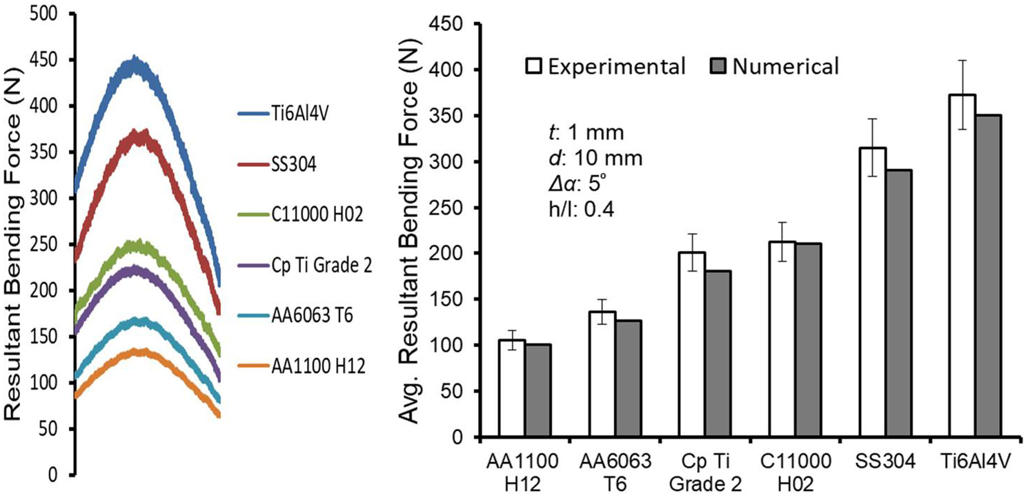
Influence of sheet materials on bending forces.
Influence of material anisotropy
The influence of material anisotropy due to the rolled sheet raw material on the bending forces was evaluated by incrementally bending parallel and perpendicular to the pre-rolled direction. The average bending force for the sheet metal bent perpendicular to lay was slightly more in comparison to parallel to lay for the given set of material and parameters (Figure 9). Grain elongation and surface texture of sheet due to rolling resulted in material anisotropy in perpendicular and parallel rolling direction. It was observed in all the tested sheet metals. Though the magnitude was different, but proportional variation was similar for all the tested metals.
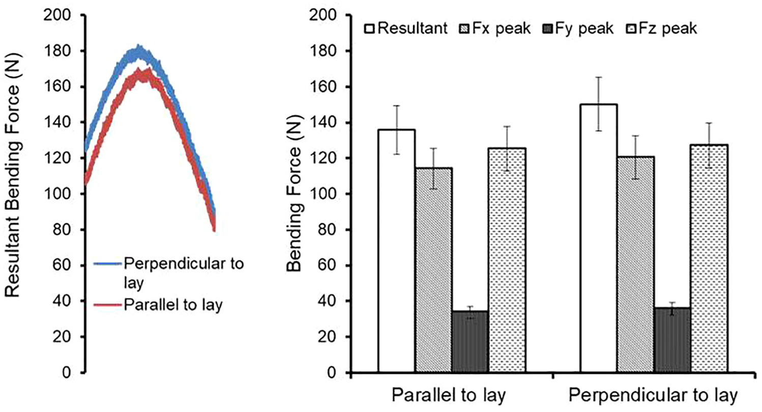
Influence of material anisotropy on bending forces for AA6063-T6.
Influence of sheet thickness (t)
The average resultant forces increase considerably with increase in sheet thickness as seen in Figure 10. The forces rises up to more than 300 N with increase in sheet thickness from 0.8 to 2 mm at the set parameters. The primary reason for increased level of bending forces (bending load and moment) is the increased moment of inertia (I) with increased thickness according to simple bending equation.
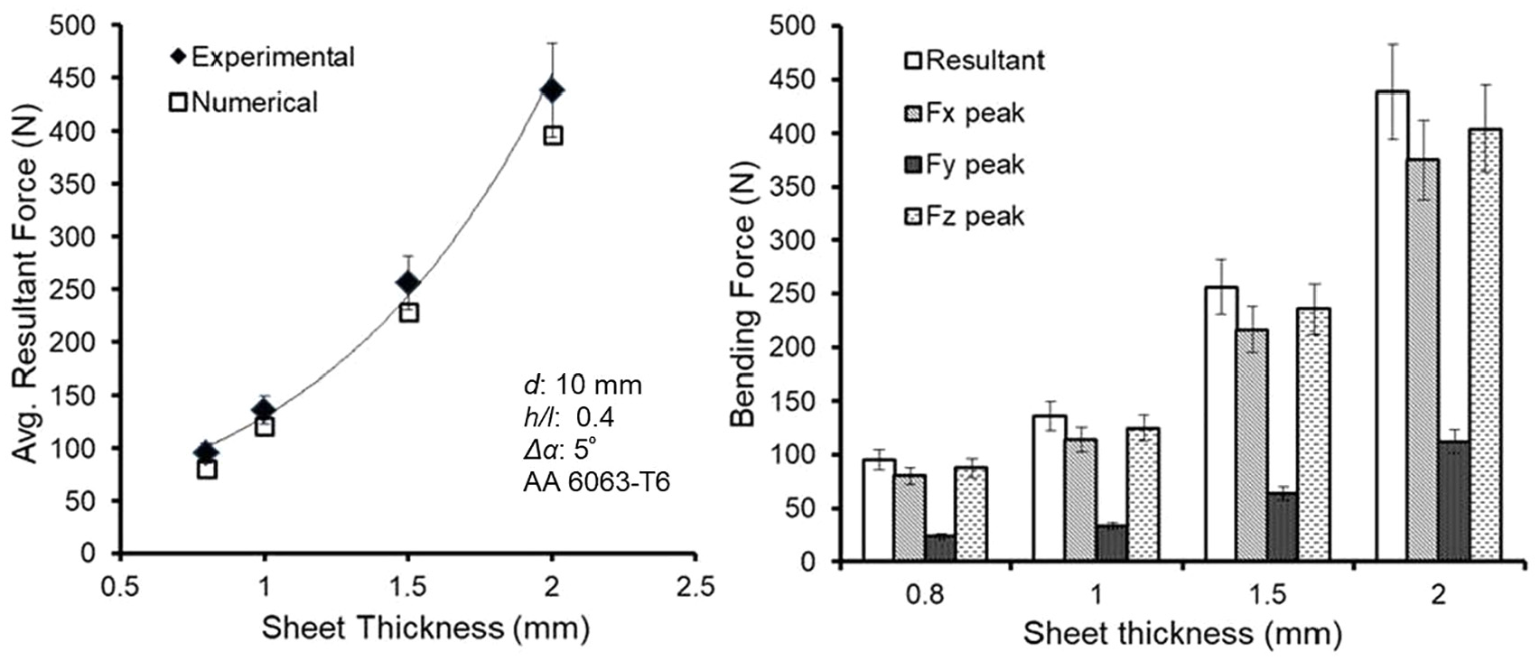
Influence of sheet thickness on bending forces.
Influence of tool diameter (d)
Figure 11 shows the average resultant force values for different tool diameters used. It is quite evident from the figure that there is no noticeable change in the magnitude of average resultant forces as the tool diameter increases. The magnitude of the forces vary in small range of 7–8 N. The possible reason for such a trend could be that the primary force of deformation was in x and z direction and in that direction the tool contact with the wall was tangential (line contact). Therefore the size of the tool does not have a significant bearing on the overall average bending forces, as irrespective of diameter of the tool the contact would be tangential.
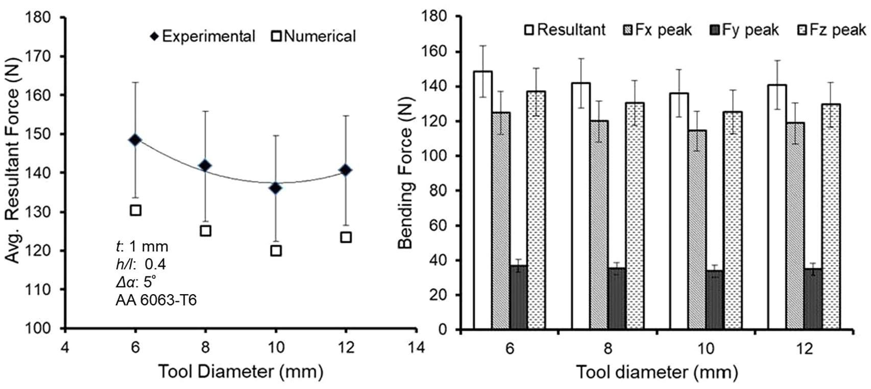
Influence of tool diameter on bending forces.
Influence of sheet height to length ratio (h/l)
Figure 12 shows the results for bending forces with varying sheet height to length ratios from 0.2 to 0.6. It is clear that the magnitude of forces reduces significantly by nearly 200 N as the sheet height to length ratio increases. The reason for the increase in average resultant force at lower height to length ratio is attributed to increased amount of resistance of the sheet at lower height, as the applied load is acting closer to the fixed end. Incremental bending of sheet can be modelled as a cantilever with a point load at the free end.
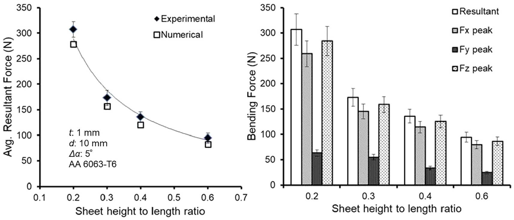
Influence of sheet height to length ratio on bending forces.
Influence of incremental bending angle (Δα)
The average resultant force increases by nearly 60 N with increase in incremental angle from 1° to 5° at set parameters, as visible from the results in Figure 13. With increase in the incremental angle, tool movement in x-direction (Δx) and y-direction (Δy) increases, thereby increasing the magnitude of deflection of the sheet at every tool travel along the y-direction (along the length of sheet). This would increase the force required for obtaining that particular amount of deflection.
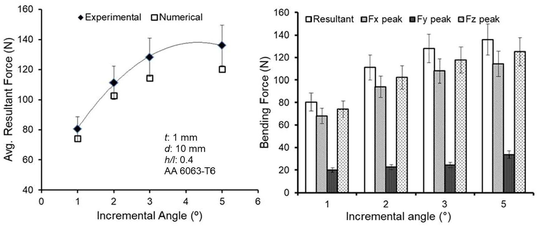
Influence of incremental bending angle on bending forces.
Regression analysis for prediction of forces
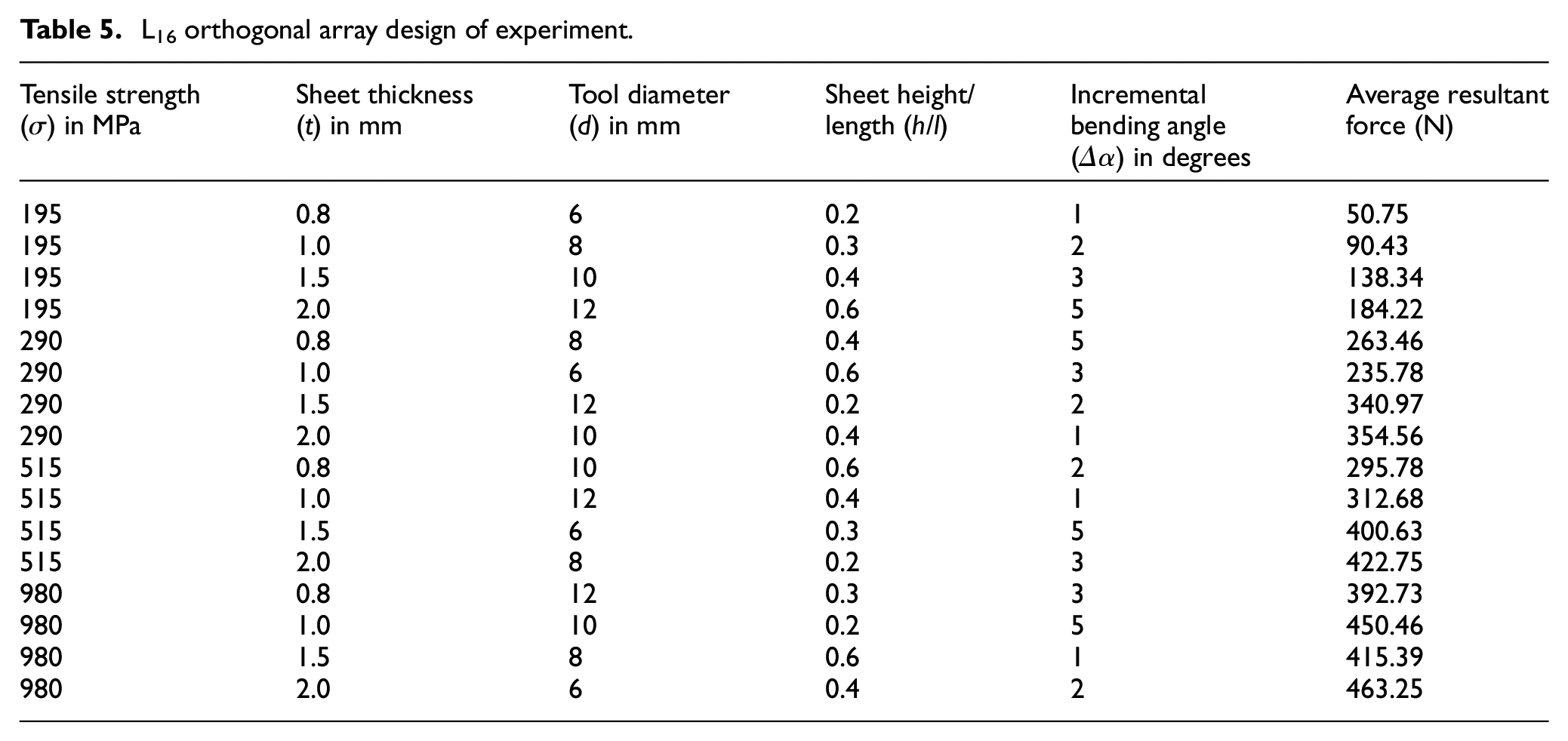
Detailed regression analysis was done to predict the forces considering all the important input process parameters that is, tensile stress of the four different sheet material (σ), sheet thickness (t), tool diameter (d), sheet height to length ratio (h/l) and incremental bending angle (Δα). Non influential parameters such as tool feed rate, tool rotation were not considered in the analysis. For this L16 orthogonal array design of experiment was employed (Table 5) was used and average resultant force was calculated.
L16 orthogonal array design of experiment.
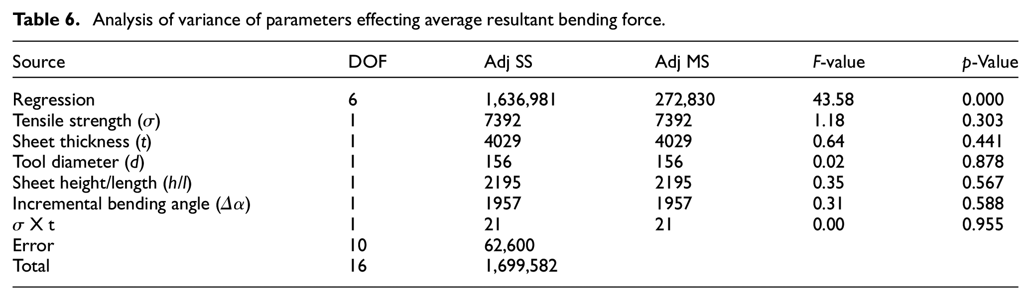
Analysis of variance of the results was conducted (Table 6) and based on that a regressive equation predicting the average resultant force (Fresultant) in incremental bending (equation (3)) was obtained with an error of less than 4%. From the analysis of variance of the results, it could be inferred that average resultant bending force primarily depended upon the sheet material (Tensile strength σ) and sheet thickness (t). Incremental bending angle (Δα) and sheet height to length ratio (h/l) also have a bearing on bending forces. The size of bending tool (d) did not have any significant effect on the bending forces.
Analysis of variance of parameters effecting average resultant bending force.

Process validation
The technical viability of incremental bending process has been verified by creating complex sheet metal geometries. Figure 14 shows the sheet metal bent at various bending angles employing uniform incremental bending. Sheet metal with multiple bends and also varying bending angles were fabricated by generating tool path on a conventional CNC vertical milling centre (Figures 15 and 16 respectively). Figure 16 depicts the sheet metal bent at varied angles with varying sheet height along the length. Sheet metal components with variety of complicated (not in line) geometries have been fabricated employing a specially designed and fabricated fixture capable of holding sheet metal of varied dimensions and at varied orientations (Figure 17). The fixture is able to hold varied size of sheet metal also at varied orientation with respect to the tool path.
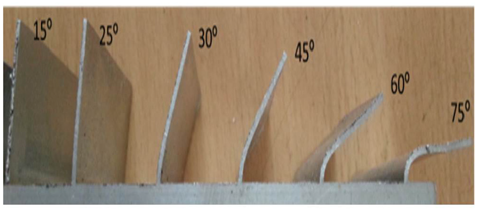
Sheet metal components bent at various bending angles.
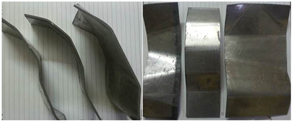
Sheet metal components with complex geometries and multiple bends.
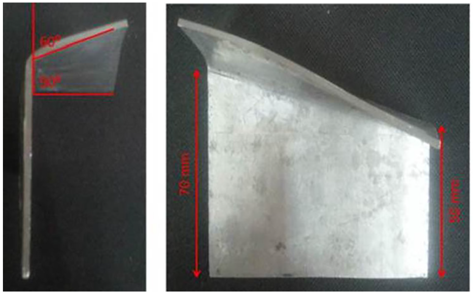
Bent sheet metal sample at varying angle and height.
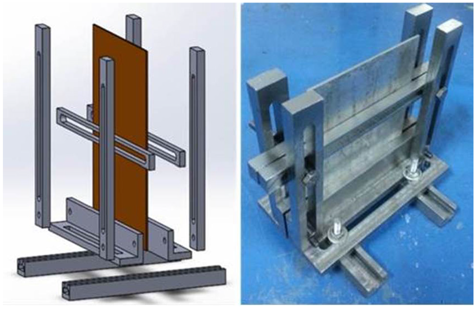
Sheet metal holding fixture.
Summary and conclusion
In the present study, the process of incremental sheet metal bending has been proposed and realised, aimed at solving issues incurring in conventional approach of fabricating such sheet metals, employing considerably simple tooling and equipment. Bending force/load trends in constant incremental bending have been established both experimentally and through finite element process simulations. Effect of various process parameters on average resultant force in incremental bending have been analysed. Load trends in incremental bending primarily depend upon sheet raw material, sheet thickness and incremental bending angle. Force evaluations at important parameters in incremental bending shall give an insight about the scale of tooling and equipment required for the process. In addition to this, sheet metal with multiple bends and also varying bending angles with varying heights were fabricated employing a specially designed and fabricated fixture capable of holding sheet metal of varied dimensions and at varied orientations. Thus, incremental nature of operation provides flexibility in shape and size during fabrication. Complex shaped sheet metal was fabricated by generating tool path employing relatively simple and inexpensive tooling and fixture on a conventional CNC vertical milling centre. Process capability in generating complex sheet metal geometries shown in the current work shall possibly pave the way of commercialising the process in near future.
Footnotes
Appendix
Acknowledgements
The authors would like acknowledge the support of Indian Institute of Technology Ropar in providing the facilities to carry out the research.
Author contributions
Arshpreet Singh conceived the research, did the experimental work, simulations and analysis. He wrote the article. Anupam Agrawal conceived the research and carried out the proofreading.
Declaration of conflicting interests
The author(s) declared no potential conflicts of interest with respect to the research, authorship, and/or publication of this article.
Funding
The author(s) received no financial support for the research, authorship, and/or publication of this article.
Compliance with ethical standards
This research follows ethical standards.
Consent to participate
The authors agree.
Consent for publication
The authors gave consent for publication.