
Abstract
Press-braking bending is a multi-step bending process and widely applied in the aerospace industry. Residual stresses and strains generated during the forming process play an important role in determining its forming parameters and bending path. This work aims to analyze the residual stresses and strains in press-braking bending parts using both the theoretical method and numerical method. First, the analytical model of residual stress and strain is established based on the elastic–plastic bending theory. Second, a fully finite element model of press-braking bending has been developed, and a procedure to simulate the multi-step bending process is presented by using the elastic–plastic large deformation finite element method. The simulation results are then compared with three-point bending experiments in terms of forming force and final shapes of the bent specimens, and excellent agreement is achieved. Finally, the results calculated from the analytical model are compared with the numerical results. The distributions of residual stresses and strains on the finished plate along the length and thickness direction, and particularly the multi-step forming effect on residual stresses and strains, are discussed. It is found that the residual stresses and strains decrease at the initial loading position along the thickness direction during the forming process of subsequent loading positions. With the same punch displacement, the residual stresses and strains at the initial loading position are less than those at the subsequent bending position.
Keywords
Introduction
Press-braking bending is a metal forming process that performs local three-point bending deformation according to a certain bend sequence to generate a desired curvature shape, 1 in which the sheet is supported by two stationary shoulders and formed using a punch. 2 This forming method possesses many advantages, such as strong flexibility to adapt different contours, simple bending dies, easy operation, short production cycle and low cost.3–5 Due to these advantages, press-braking bending has been widely used in the aircraft manufacturing. 6
The bending process is an elastoplastic process in which the metal is loaded into the plastic range and then elastic unloading is performed. 7 Plastic deformations in each bending step result in residual stresses and strains, which may potentially affect the determination of forming parameters and bending path. However, most of the current research focused on the study of springback behavior in bending process,8–11 and the residual stresses and strains caused by cold bending process have not been paid enough attention. Therefore, it is of importance to predict residual stresses and strains of the formed plates in the forming process.
Different methods, such as the experimental method,12–14 analytical method15–17 and finite element (FE) method,18–20 have been applied to analyze and predict the residual stresses and strains in press-braking bending parts. The difficulties with the experimental method to measurement the residual stresses and strains induced by bending process are summarized as following: 21 (1) Measuring residual stresses in press-braking bent parts in the lab is time consuming and of limited accuracy. (2) It is also difficult to quantify plastic strains by experimentation. (3) The measurement method cannot obtain the information required to understand the variation of residual stresses and strains over multi-step bending operations. To overcome the difficulties, the analytical method has been attempted by some researchers. Quach et al. 15 presented an analytical model to predict the residual stresses and equivalent plastic strains in press-braked stainless sections. Shen et al. 16 derived the maximum residual stress formula in cold-formed wide plates based on elastic–plastic bending theory of cure plate. Joudaki and Sedighi 17 derived the formulas of stress distribution and maximum residual stress in beam bending based on three different material behavior models. The residual stresses and strains calculated by the analytical model in the above study show a close agreement with the numerical results. However, it is not available to model the multi-step bending process theoretically to predict residual stresses and strains in formed plates.
Numerical simulation based on the FE method has become a powerful tool for studying plastic forming problems and has been widely used in the research of part bending as it saves time and cost.22,23 Quach et al. 18 presented an FE method for the prediction of residual stresses in formed sections produced by press-braking process. Thipprakmas 19 investigated the influences of punch height on the bending angle by the FE method in the V-bending process. Esat et al. 20 used FE analysis software to simulate the process of angular bending and wipe bending, and the influence of different aluminum materials of different thickness on springback was analyzed. The numerical results of the above studies have achieved good agreement with laboratory measurements or empirical data. However, these analyses are focused on single-point bending, and only half of the whole part is modeled. As for multi-step press-braking bending process, the punch and dies are moved discontinuously and the residual stresses generated in the former forming step could contribute effects to the subsequent bending step. Therefore, it is necessary to develop a full FE model of press-braking bending process. Liu et al. 24 performed FE simulation for three-point cold bending process of thick steel plates and analyzed the distributions of residual stresses and strains. During the bending process, the same displacement load is applied at three pre-defined loading positions. However, in real conditions, different levels of indentation displacements are imposed on different loading positions during multi-step bending process, and the variation of residual stresses and strains over multi-step bending operations has not been investigated. Understanding the change law of residual stress and strain distribution in press-braking bending parts is of importance to the studies on bending path planning and forming process optimization to decrease the residual effects. 25
In this study, the analytical model of residual stress and strain is established based on elastic–plastic bending theory, and a full FE analysis model, not a quarter or a half of the whole part, of bending process is developed. Meanwhile, a procedure to simulate the multi-step bending process is proposed by using the elastic–plastic large deformation FE method. Then, three-point bending tests are conducted on three specimens, and the FE results in terms of bending force and final shapes of bent parts are compared with the experimental values to validate the results of FE analysis. Moreover, the results calculated from the analytical model are compared with the numerical results. The distributions of residual stresses and strains along the length and thickness direction are analyzed. In particular, the influences of multi-step forming operations of press-braking bending on residual stresses and strains are discussed.
Theoretical analysis of residual stresses and strains
The stress distribution of the bent plate in the cross-section is shown in Figure 1.
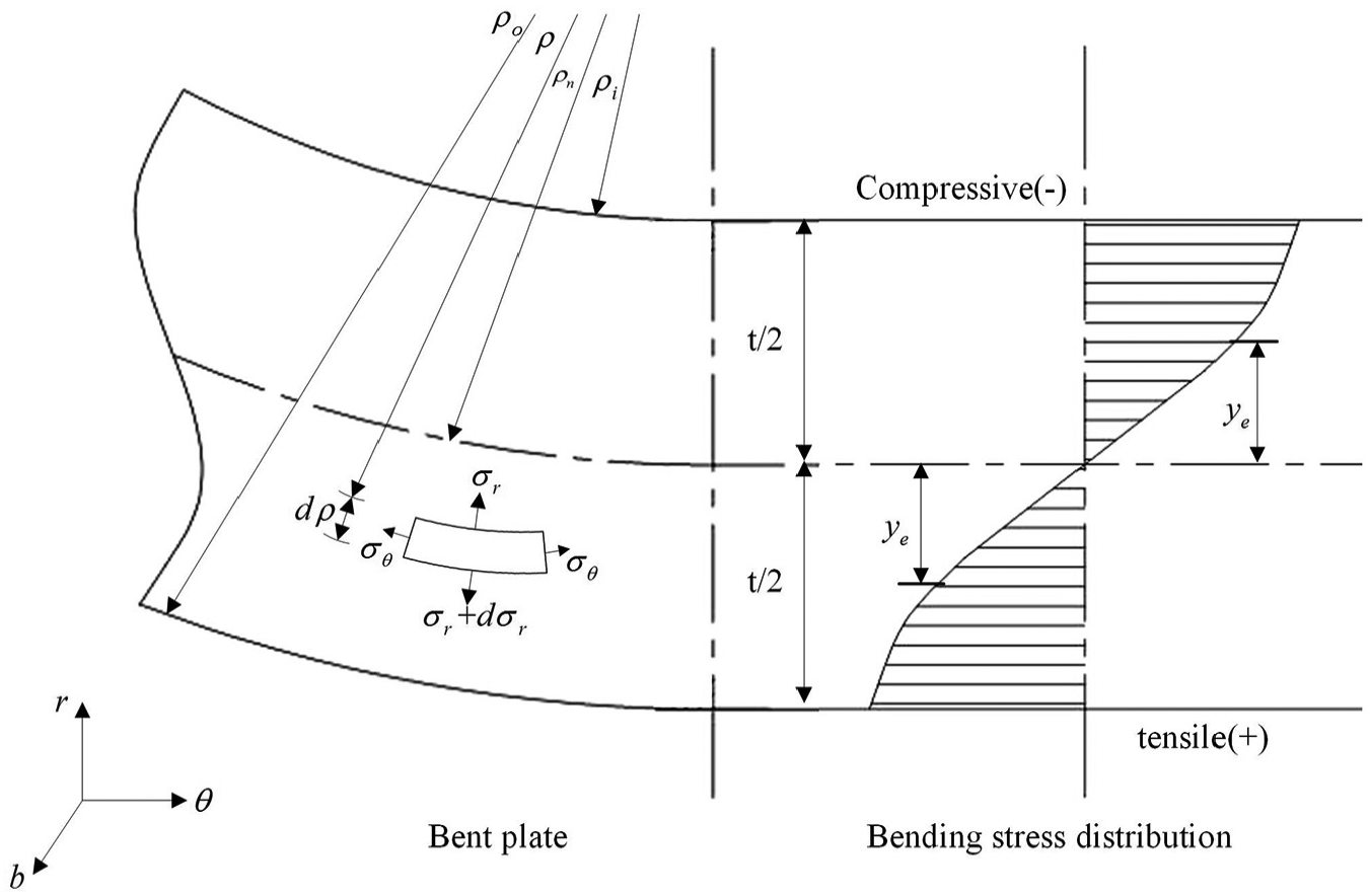
Bent plate and stress distributions in thickness direction.
Assumptions for the springback prediction model are listed as follows:
The volume of the material remains constant during the bending process,
Press-braking bending for wide plate obeys the plane strain condition,
The contact region between punch and sheet is assumed to be circular, 26 and the neutral surface of bending is presumed to remain at the same position.
The isotropic Swift hardening law,27,28
The shear stress during bending is ignored, and the plane cross-sections remain plane and perpendicular to the deformed middle surface of the sheet. 29
The von Mises criterion is used for plastic yielding, which is suitable for the ductile materials.
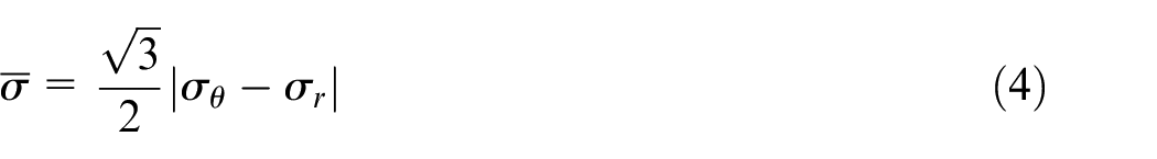
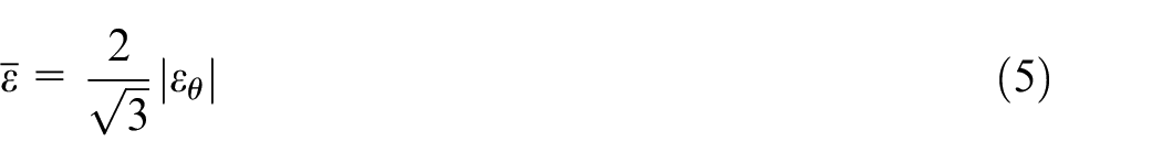
The material obeys the Hencky total strain theory 30 when the material undergoes plastic deformation. According to assumption (2), the stress in the width direction can be expressed as follows
where
According to the Mises stress–strain relationship and assumptions (2) and (5), the equivalent stress and equivalent strain can be written as follows
Substituting equation (1) into equation (2), the equivalent stress can be obtained as equation (4). The equivalent strain can be written as equation (5) according to equation (3), assumptions (1) and (2)
According to assumption (4), equations (4) and (5), equation (6) can be obtained
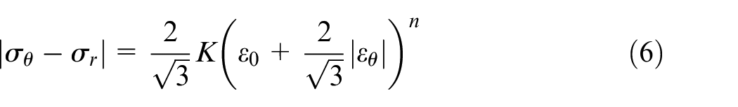
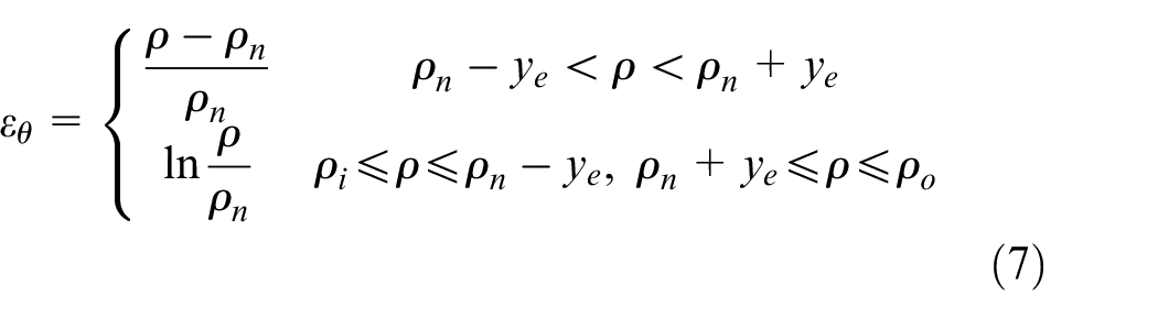
where tangential strain,
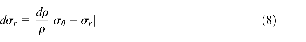
According to the static equilibrium condition shown in equation (8), the radial stress can be obtained with the boundary condition of
where
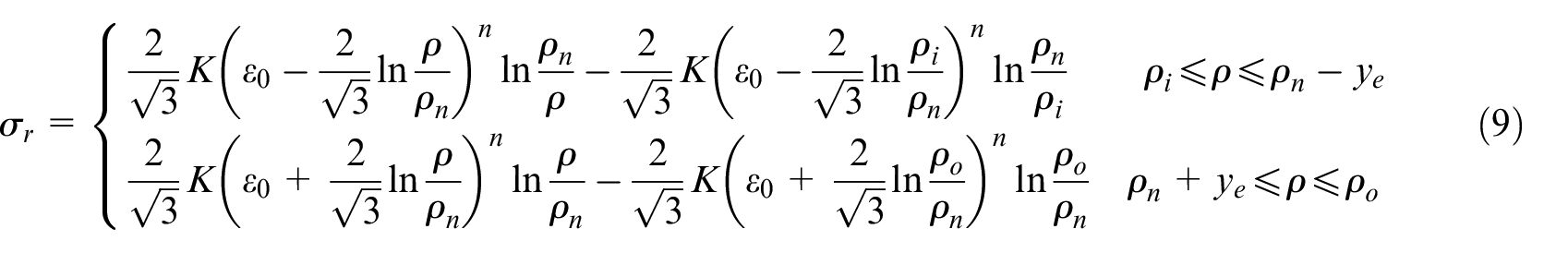
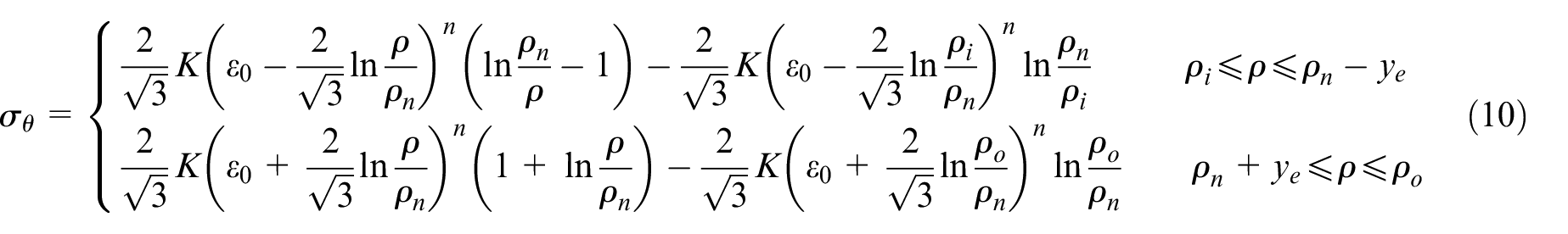
According to equations (6) and (9), the distribution of tangential stress,
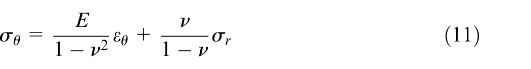
In the elastic deformation zone, the stress–strain relationship of material obeys the general Hook’s law. According to assumption (2) and the expression for
where
According to equations (6) and (11), the radial stress in the elastic deformation zone can be written as equation (12) (assuming that the radial stress
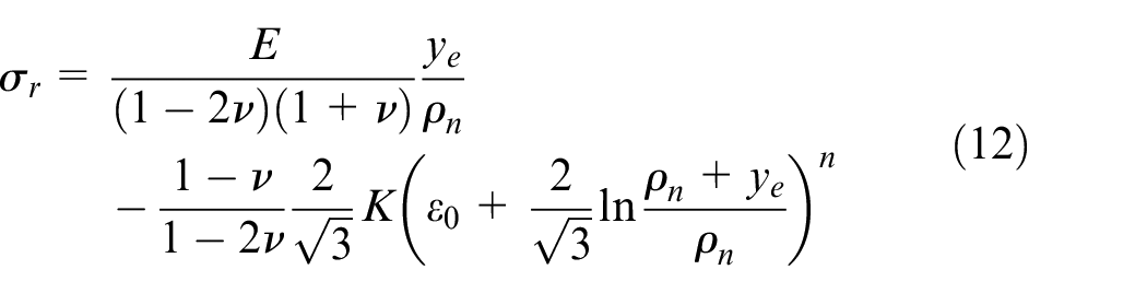
The distribution of tangential stress,
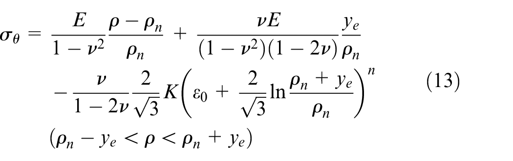
The bending moment is defined below
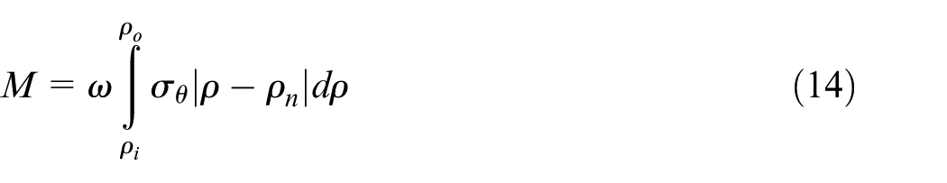
where
The elastoplastic curvature change is equal to the elastic curvature change caused by the bending moment based on the classical springback theory, that is, the springback bending moment is equal to the loading bending moment in magnitude, and opposite in direction. The curvature change after the springback is achieved below31,32
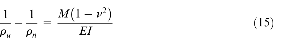
with
The residual tangential stress,

where
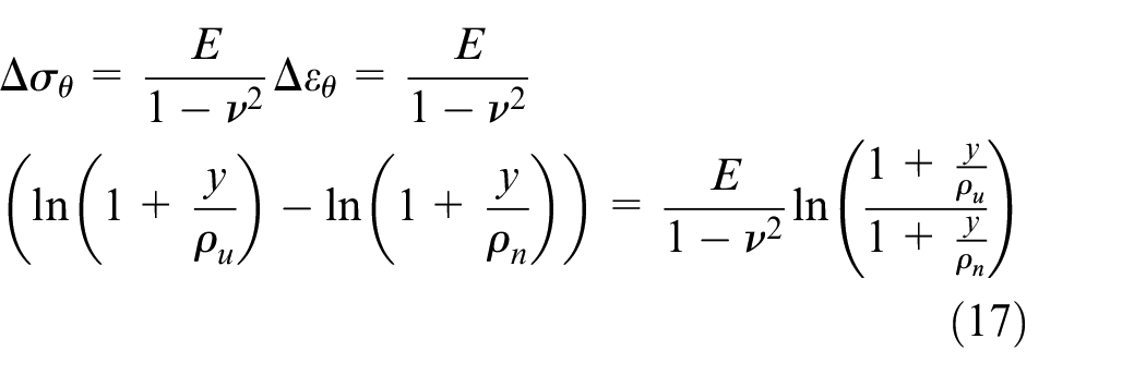
where y is the vertical distance from the neutral axis and
where
FE simulation
The press-braking bending process includes loading part and unloading part and the motions of dies for different loading positions. Meanwhile, the constraints are different for these processes. In this section, a full FE model for press-braking bending is established, and the simulation of the forming process is considered. First, the material properties are determined with uniaxial tensile test. Then, the FE algorithms and procedures are presented to simulate the whole forming process.
Material properties
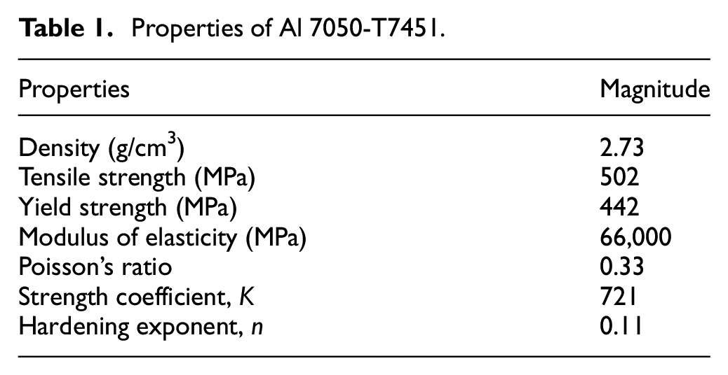
The aluminum alloy material, 7050-T7451, which is commonly used in aerospace and aviation is used in this study. The properties of the material listed in Table 1 are obtained with the uniaxial tensile test. The true stress–strain, used to represent the strain hardening behavior of the material in subsequent bending simulation, is obtained by converting engineering stress–strain curve, as shown in Figure 2.
Properties of Al 7050-T7451.
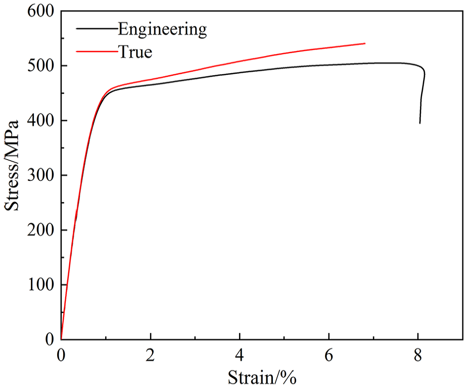
Stress–strain curve of the 7050-T7451 alloy.
FE model and simulation process
Figure 3 shows the full FE model for press-braking bending established in ABAQUS environment. The FE model consists of punch, support bodies, specimen and two contact surfaces. The material is assumed to be isotropic, and von Mises yield criteria are used. In the assembly model, the initial relative position of these components has been determined. The time period for bending analysis is set to 0.5, and the time period for springback analysis is the default 1.0. The punch and support bodies are presumed to be rigid bodies (element type: R3D4), while the specimen is considered as a deformable body (element type: C3D8R). Surface-to-surface contact is used to define the two contact surfaces. All the rigid bodies are set as the first surfaces, and the deformable body is set as the second surface. The penalty contact method and finite sliding are defined in the simulation, and the classical Coulomb model is defined as the friction conditions of the two contact surfaces. The displacement loading mode is adopted, and the punch displacement is defined as the position difference between the final position of the punch motion and the starting contact position of the punch and the part. The degrees of freedom of the support bodies are completely constrained during the bending process, and the displacement load of the punch is realized through the reference points (RPs). The moving of the support bodies and the punch to the next bending position are also realized through the RPs.
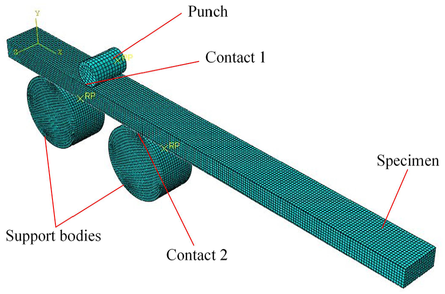
FE simulation model.
The FE algorithms and criterions to simulate the multi-step press-braking bending process and springback process are summarized in Figure 4. The explicit algorithm is used to simulate the bending process since it guarantees convergence and analysis with improved efficiency. 34 The springback model is established by modifying the constraints and removing the dies and loading of the FE model of the previous bending step. The bending stresses, strains and displacements obtained from the bending step are considered as the initial conditions of the springback model to simulate the springback process with the implicit algorithm. 35 The final shape of the plate can be obtained when the bending and springback process of all the loading positions are finished, or the position of punch and supporters need to be redefined to finish the multi-step forming process.
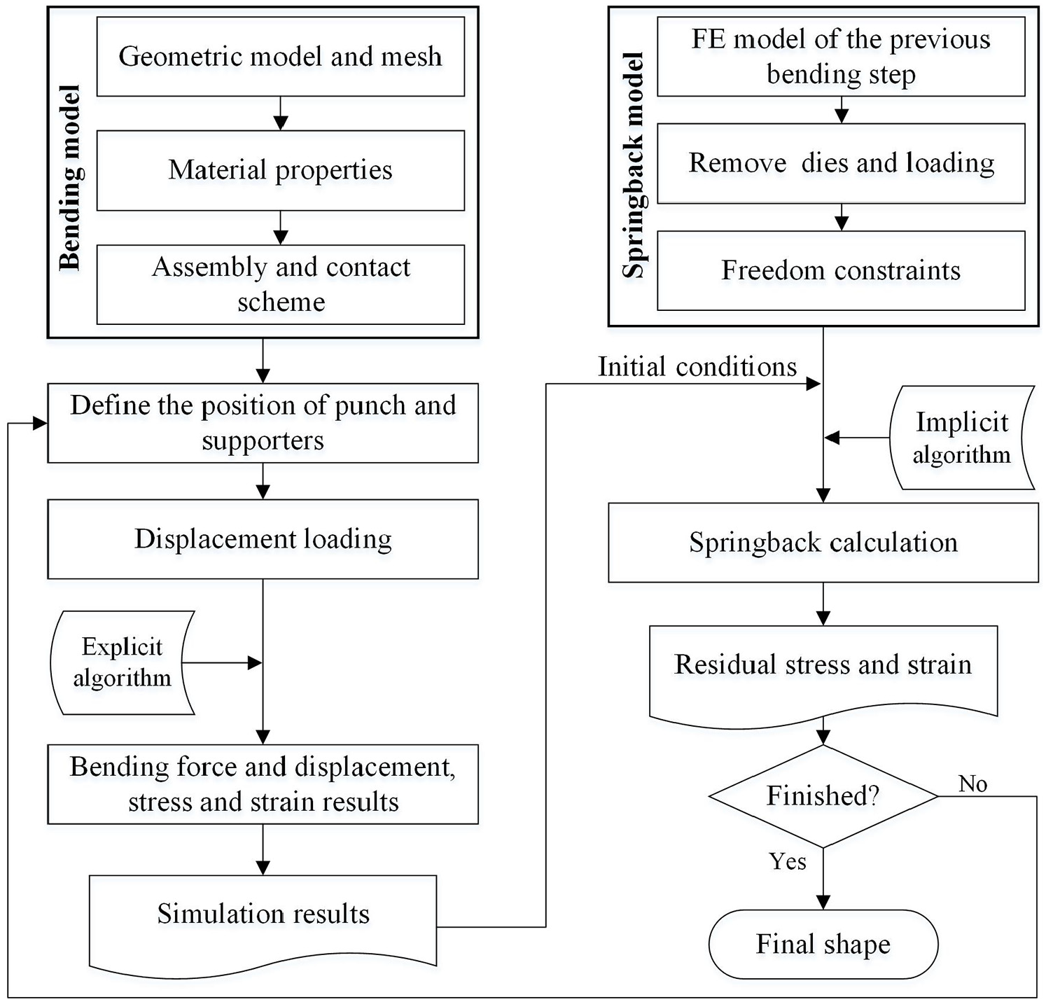
Simulation process of press-braking bending.
Experimental verification
Three-point bending experiments
The specimen used in this work is a rectangular block with the dimension of 200 mm × 15 mm × 7.5 mm (Figure 5(a)), which is designed based on the joint of a real aircraft wing panel (the joint is formed with the method of press-braking bending) according to geometrical similarity. The three-point bending experiment is carried out on the CSS-44100 testing machine. The diameters of punch and support bodies available in the laboratory are 10 and 30 mm, respectively. The distance between the support bodies is designed to be 50 mm according to the diameters of dies and dimensions of the specimens. The displacement load is 3 mm at loading position (1) and (3) and 3.5 mm at loading position (2). The punch displacement is determined similarly with the practical fabrication. The displacement load is applied step by step along the length direction of the test workpiece, and Figure 5(b)–(d) shows the loading sequence of the press-braking bending process. The bending force is also recorded during the forming process. The contours of the bent specimen after unloading are obtained by the Creaform 3D scanner, which is shown in Figure 6.
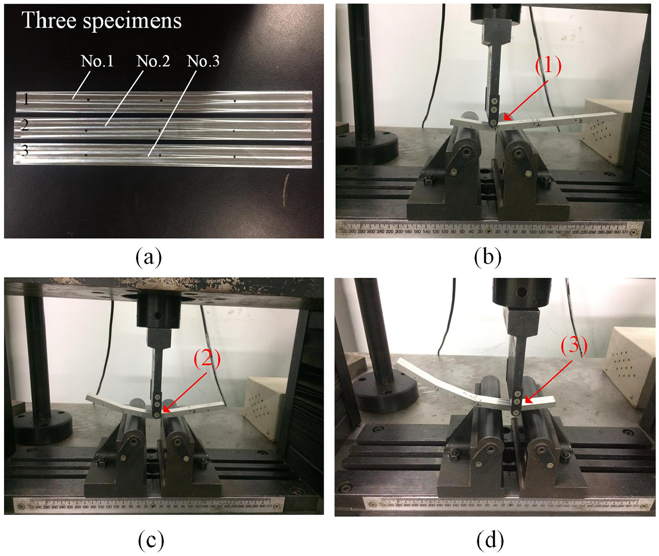
Bending forming experiments: (a) specimens, (b) the first bending, (c) the second bending and (d) the third bending. The notations (1), (2) and (3) are loading positions.
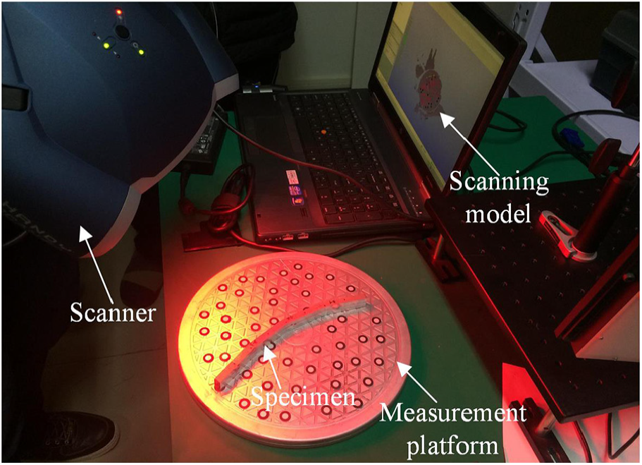
Scanning of the specimen contour.
Comparisons of forming forces and final shapes
The reliability of forming simulation is directly influenced by the accuracy of bending force during bending process. 36 Therefore, the simulation results are validated with three-point bending experiments in terms of forming force versus displacement curves, and final shapes of the bent specimens are also compared in this section.
Figure 7 shows the comparisons of bending force versus displacement curves between FE simulations and experiments under the punch displacements of 3 and 3.5 mm. It can be seen that the FE simulation results have a good agreement with the experimental results. However, the bending force of simulation results is slightly smaller than the experimental results. It can be due to the following reasons: the compressive mechanical properties are not taken into account in the material model and the difference between the actual material thickness and the material thickness in the simulation.
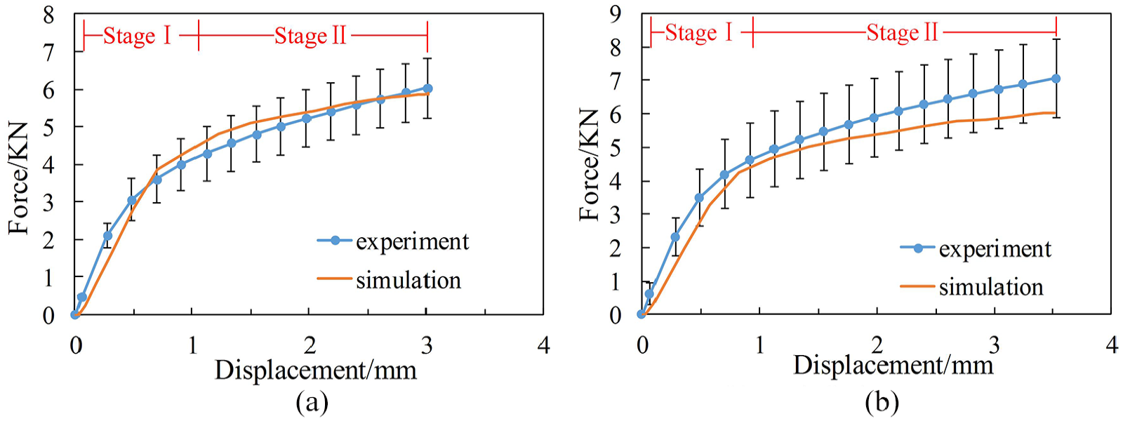
Comparison of bending force between experiment and simulation. (a) punch displacement: 3 mm and (b) punch displacement: 3.5 mm.
From the curves, it is observed that the change of bending force is mainly divided into two stages: (1) the bending force increases greatly as the punch displacement increases at this stage and (2) the bending force increases steadily when the displacement exceeds 1 mm.
To verify the final geometry of the specimens after the bending process ends, the contours obtained from the FE simulations and three-point bending experiments are illustrated in Figure 8(a), (b). The nodal coordinates of the bent plate in the simulation are exported and compared with the contours of the bent specimens, as shown in Figure 8(c).
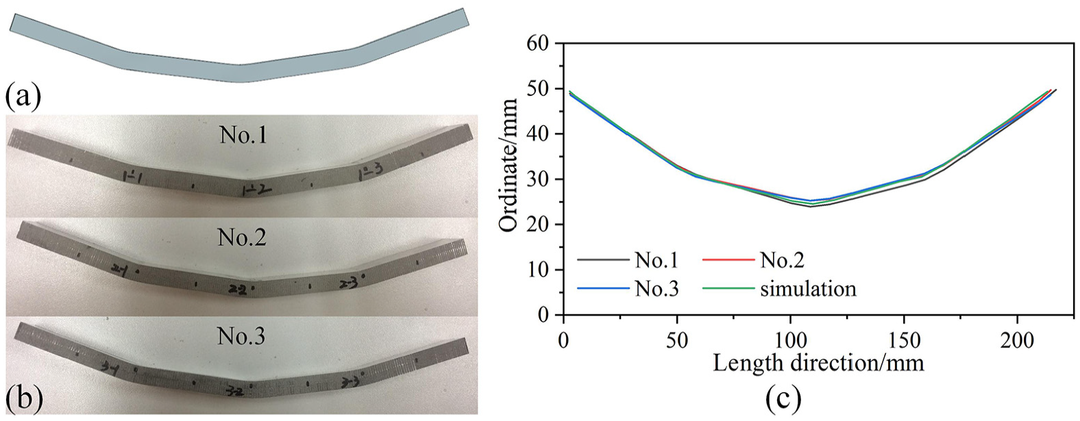
Bent specimens obtained from (a) simulation and (b) experiment; (c) comparison of final shape between simulation and experiment.
In Figure 8(c), the geometry shapes of the specimens obtained from the simulation have a good agreement compared with the experimental results, and the error is less than 10%. The errors can be owed to various origins, such as bending operation, method of measurements, fitting method and so on. However, the prediction accuracy can meet the engineering requirements from the engineering view of point, which also verifies the validity and reasonability of the numerical method.
Results and discussion
The comparison of residual stresses between theoretical analysis and simulation analysis is discussed first. To investigate and quantify the residual stresses and strains in the press-braking bending process, four distinct surfaces (upper surface, subsurface 1, subsurface 2 and lower surface as shown in Figure 9) through the thickness are selected. Furthermore, the variation of residual stresses and strains over multi-step bending operations (as shown in Figure 5) of the forming process is also investigated numerically.
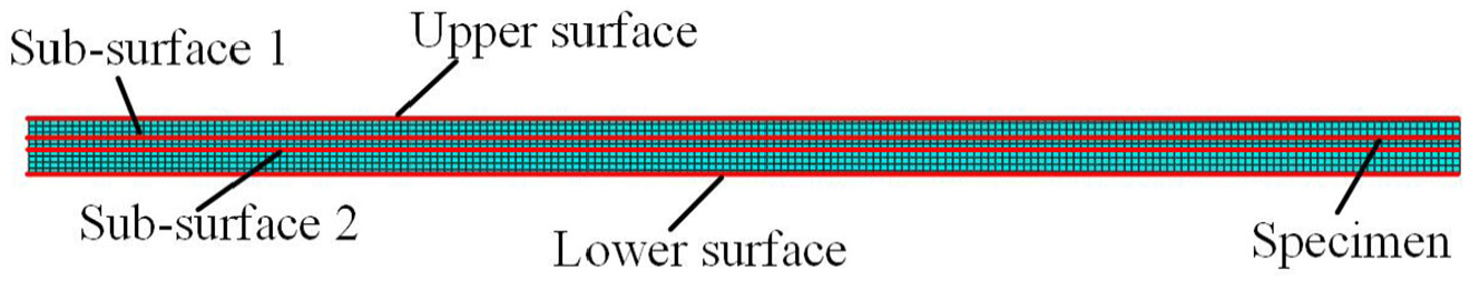
Four selected surfaces through the thickness to check the residual stresses and strains.
Residual stress analysis
During the bending process, the tangential stress is the main stress. 37 The comparison of tangential stresses in the thickness direction after bending and unloading between theoretical analysis and simulation analysis under the punch displacement of 3 and 3.5 mm is shown in Figure 10(a)–(d), respectively. It is clear that the bending stresses and residual stresses obtained by the two methods have the same tendency. The residual stresses are nonlinearly distributed through the thickness, and the distribution coincides with the standard residual stress distribution (the zigzag stress distribution pattern, 38 namely, the change rule of tensile-compressive-tensile-compressive). The maximum stresses obtained by theoretical and simulation calculation are indicated in Figure 10. It can be seen that the maximum bending stresses obtained by the two methods are about 600 and 540 MPa, and their locations are close to each other. The maximum residual stresses obtained by the two methods are more than 300 MPa and also close to each other in values, while there are differences in locations. This can be due to the classical springback theory that the springback bending moment and the bending moment are assumed equal in magnitude and opposite in direction. 30 However, the difference does not affect the study of the change law of residual stress and strain distribution in this article. Therefore, the numerical method is used to study the variation of residual stresses and strains over multi-step bending operations of the forming process, as shown in Figures 11–15.
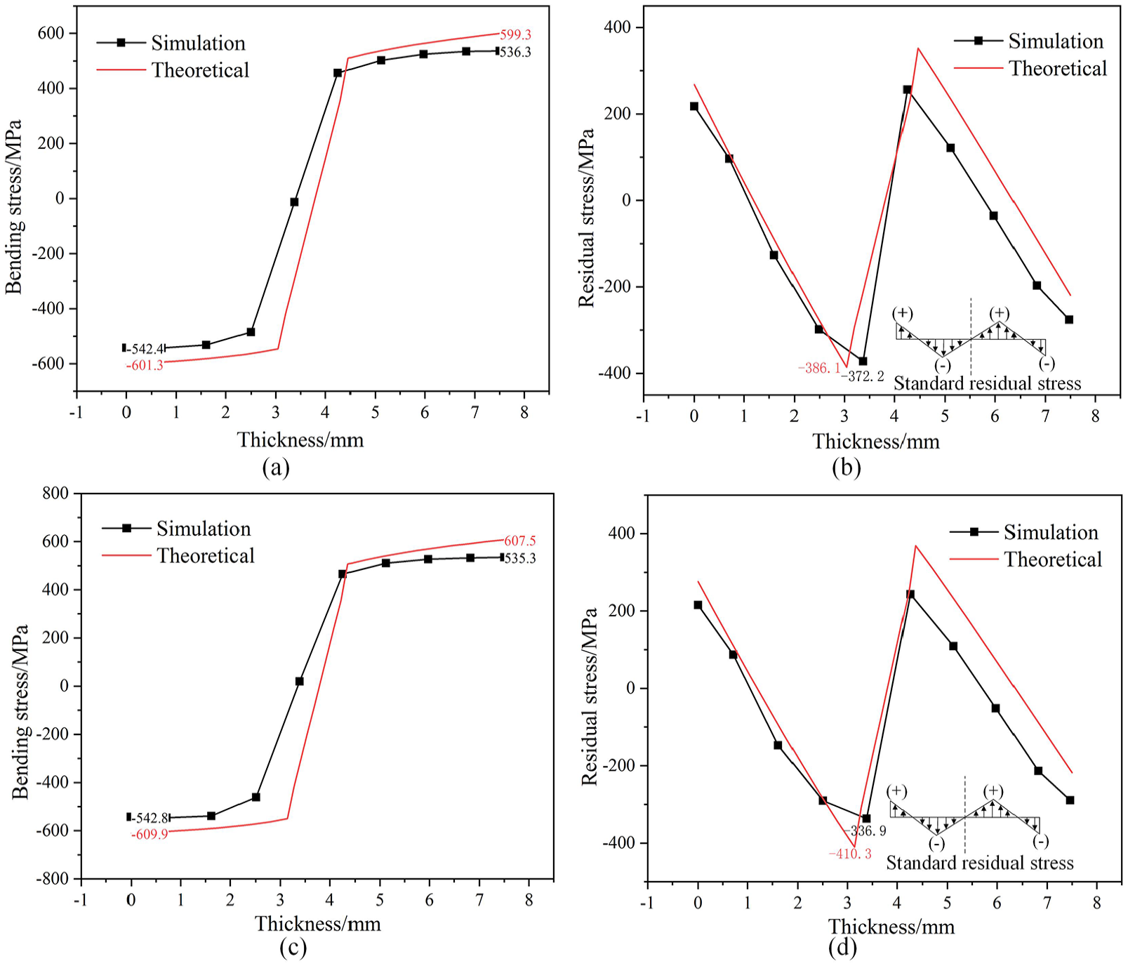
Comparison of stress distribution between theoretical and simulation analysis in thickness direction: (a) bending stress under the punch displacement of 3 mm, (b) residual stress under the punch displacement of 3 mm, (c) bending stress under the punch displacement of 3.5 mm and (d) residual stress under the punch displacement of 3.5 mm.
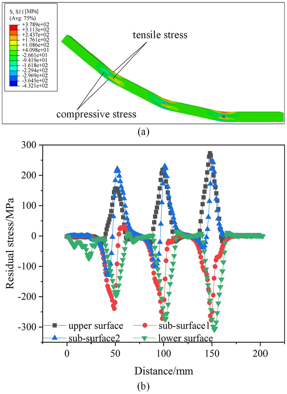
Residual stress distribution in the longitudinal direction at three loading positions: (a) residual stress distribution nephogram and (b) longitudinal residual stress.
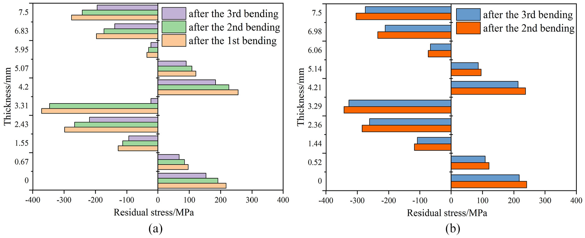
Residual stress distribution along the thickness direction at (a) loading position (1) and (b) loading position (2) and their variation with the subsequent bending operations.
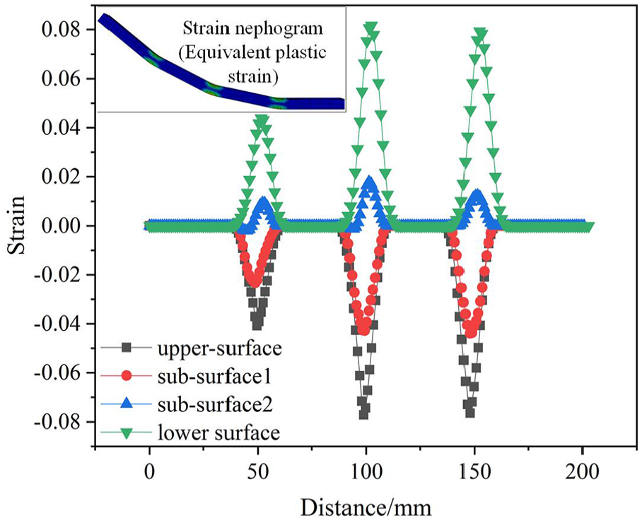
Residual strain distribution in the longitudinal direction.
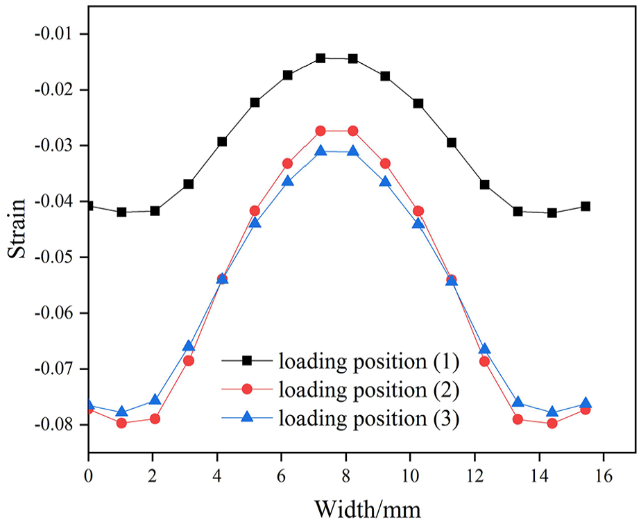
Residual strain distribution in the width direction at three loading positions after the continuous bending operations.
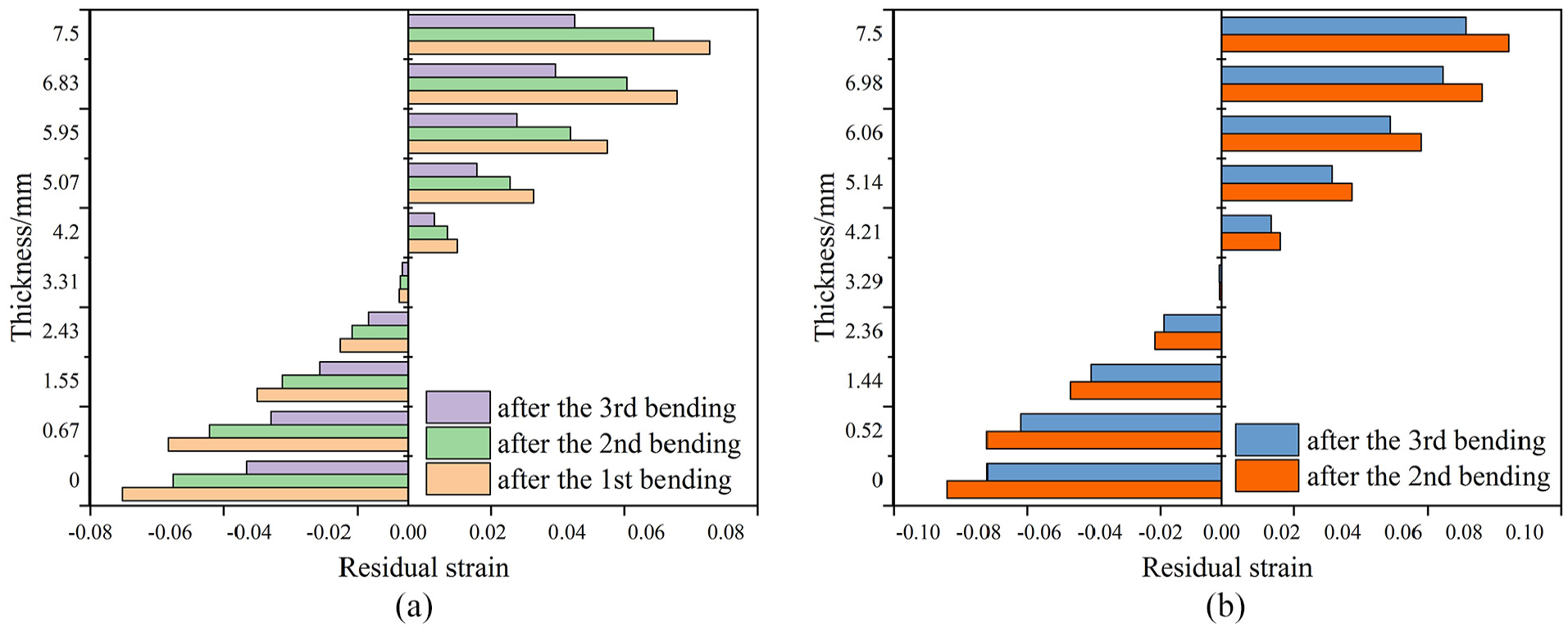
Residual strain distribution along the thickness direction at (a) loading position (1) and (b) loading position (2) and their variation with the subsequent bending operations.
The residual stress distribution in the longitudinal direction after loading and unloading at the end of the simulation is shown in Figure 11. It is noticed that tensile residual stress occurs at the upper surface, and compressive residual stress presents at the lower surface of the bent plate, as shown in Figure 11(a). It is quite different from the bending stresses (Figure 10(a), (c)) that the compressive stresses are generated on the upper surface and tensile stresses are generated on the lower surface on the bending zone. This can be explained as follows: it is an elastic deformation process during unloading. The part where plastic deformation has occurred cannot be restored to its original size, and it will hinder the recovery process of the elastic part. Therefore, the stress state of the plastic deformation part will be changed conversely during the unloading process.
In Figure 11(b), the residual tensile and compressive stress have their largest values near the neutral layer rather than the upper or lower surface since the rebound causes a large amount of stress to be relaxed. It is also verified by Jiang et al. 22 Specifically, it is also found that although the punch displacement at position (3) is smaller than that at position (2) and is the same with the position (1), the residual stress at position (3) is the largest. This is because of the initial loading suffered by the bent plate. Therefore, it can be concluded that the residual stresses due to the initial bending affect the subsequent bending position and lead to the increase of residual stresses at the subsequent bending position with the same punch displacement.
To investigate the interactions between the residual stresses and multi-step bending operations, the distribution of residual stresses along the thickness direction at loading position (1) and loading position (2) and their variation with the subsequent bending operations are shown in Figure 12. Figure 12(a) shows the residual stress distribution along the thickness direction at loading position (1) and its variation with the second bending operation and the third bending operation. Figure 12(b) shows the residual stress distribution along the thickness direction at loading position (2) and its variation with the third bending operation. It is found that the residual stress at loading position (1) decreases along the thickness direction with the second and third bending operations. Similarly, the residual stress at loading position (2) decreases along the thickness direction with the third bending operation. Therefore, it can be concluded that the residual stress along the thickness direction at the initial loading position decreases with the bending of subsequent loading positions.
Residual strain analysis
The residual strain distribution along the longitudinal direction of the bent specimen after unloading is shown in Figure 13. It can be found that the maximum plastic strains mainly focus on specimen surfaces and the strains near the neutral surface are small because the material near the neutral surface is in elastic state and results in complete recovery after unloading. Meanwhile, it is also observed that the maximum residual strains appear around the punch, and the strains away from the punch remain low.
The residual strain distribution along the width at three loading positions after the continuous bending operations is shown in Figure 14. It is obvious that residual strain underneath the punch is compressive strain at the three loading positions. The residual strains at loading position (2) and loading position (3) are similar, and both of them are larger than that at position (1). Meanwhile, the residual strain of the specimen underneath the middle position of the punch is the lowest, and the edge is larger. This is because the sheet material produces relatively large plastic deformation only in the edge regions where the material fluidity is good. It can be concluded that the position near the edge of the specimen in the width direction caused plastic deformation much more easily.
The residual strains at loading position (1) and loading position (2) along the thickness direction and their variation with the subsequent bending operations are plotted in Figure 15. There are compressive strains on the upper surface and tensile strains on the lower surface of the parts, and it is observed that the residual strains distributed linearly through the thickness. The results are consistent with the research results of literature. 24 It is also verified that the maximum residual strains mainly focus on specimen surfaces and remain low close to the neutral surface. Furthermore, the residual strain along the thickness direction at the initial loading position decreases with the bending of subsequent loading positions. It is consistent with the variation of the residual stress distribution along the thickness direction at loading position (1) and loading position (2).
Conclusion
The residual stresses and strains in press-braking bending parts are analyzed using both the theoretical method and numerical method, and the variation of residual stresses and strains over multi-step bending operations is investigated numerically. The main conclusions are summarized as follows:
The numerical results show that tensile residual stress occurs at the upper surface, and compressive residual stress presents at the lower surface of the bent plate. The residual stresses due to the initial bending affect the subsequent bending position and lead to the increase in residual stresses at the subsequent bending position with the same punch displacement.
The maximum plastic strains mainly occur at specimen surfaces and around the punch, while the strains near the neutral surface and away from the punch are small. The residual strain at the initial loading position is less than that at the subsequent bending position with the same punch displacement, and the position near the edge of the specimen in the width direction caused plastic deformation much more easily.
The residual stresses and strains along the thickness direction at the initial loading position decrease with the bending of the subsequent loading positions. At present, we only analyze the distributions of residual stresses and strains considering multi-step forming effect during the press-braking bending process, but it has not been considered to control the distribution and magnitude of residual stresses and strains through forming path planning. In our future research, we will study the forming path planning of press-braking bending based on the analysis of residual stresses and strains.
Footnotes
Appendix 1
Declaration of conflicting interests
The author(s) declared no potential conflicts of interest with respect to the research, authorship and/or publication of this article.
Funding
The author(s) received no financial support for the research, authorship and/or publication of this article.