
Abstract
Wire electrical discharge machining (WEDM) technology is often used for the final machining of parts to the required surface quality without further finishing operations. At the same time, WEDM has a significant advantage over other machining technologies, and in the fact, it is possible to machine all materials, regardless of their hardness or toughness, it only needs to be at least electrically conductive. Aviation nickel superalloy Mar-M247, which is usually machined to the final form by parts using WEDM, was the subject of research in this study. In order to find the optimal setting of machine parameters (Pulse on time, Pulse off time, and Discharge current) for multicut machining, an extensive design of experiment was performed with a total of 54 circles, which optimized the cutting speed in the first and second cuts and the topography of the machined surface was taken into account in the third cut. Subsequently, an analysis of the topography and morphology of the machined samples was performed, including an analysis of the condition of the subsurface layer. The study also included the analysis of the lamella in a transmission electron microscope. It was found that with the maximization of the cutting speed in the third cut, the surface topography deteriorates proportionally, but it also leads to the complete removal of all cracks formed in the first cut.
Introduction
Wire electrical discharge machining (WEDM) is an unconventional machining technology that, unlike traditional conventional technologies, does not use mechanical work to remove material, but electrical energy in the form of electrical impulses. WEDM is based on the use of thermal energy, which is converted into an electric discharge generated between the electrodes, which form a workpiece and a thin wire with diameters of 0.3–0.02 mm, most often made of brass or copper. Other suitable materials for wire electrodes are molybdenum or tungsten, and coated or composite wires are also used. The eroding process must always take place in the presence of a dielectric medium, which is most often presented by deionized water or mineral oil, which prevents corrosion of the cobalt binder in sintered carbides. From the gap between the tool and the workpiece, the eroded particles of material in the form of small balls are washed out by the flowing dielectric liquid, because if the two electrodes come into direct contact, the eroding process is interrupted.1–3
Wire electrical discharge machining enables the requirements for machining of newly emerging, difficult-to-machine conventionally materials to be met in the required time, with the appropriate accuracy and quality with regard to the increasingly demanding ecological aspects of the production process. For this reason, WEDM is an indispensable production technology in many areas of industry, such as automotive, aerospace, medical, military, and energy. The WEDM principle allows not only the division of the material into the desired shape but also with the use of multicut technology, where multiple cuts are distanced from each other by the offset, allows a significant increase in the accuracy of the part or its surface quality. The part is thus machined using several successive cuts, which allows a significant reduction in roughness and at the same time this method increases the quality of the subsurface layer because the cracks formed during the first cut are usually eliminated by the following cuts.4,5
The nickel superalloy Mar-M247 is a refractory, heat-resistant, and corrosion-resistant alloy that has been specially developed for the use in the energy, petrochemical, aerospace, marine, and automotive industries for combustion turbine components and their components. 6
Wire electrical discharge machining is a process with many input variables, the detailed understanding of which leads to streamlining of the entire production process, including reducing the machine times and thus maintaining the competitiveness of this relatively energy-intensive technology. The purpose of this study is to optimize the machining of nickel alloy Mar-M247 using a design of experiment, which optimizes not only the cutting speed but also the quality of the surface and subsurface layer, all done in each of the three cuts (multicut technology). This study builds on and benefits from extensive previous research on materials machined with WEDM, such as Hardox steel, 7 B1914, 8 Creusabro, 9 or Hadfield steel, 10 the occurrence of defects arising after this type of machining, 11 or analysis of the oxide occurrence on WEDM surfaces. 12 The novelty of this study lies mainly in the fact that the machining of Mar-M247 using WEDM has not yet been investigated in any similar study. The obtained results are potentially very valuable not only from a theoretical point of view but especially from a practical point of view when they will be used to optimize the production of combustion turbine components.
Literature review
Klocke et al. 13 compared three roughing operations in his study while machining titanium- and nickel-based alloys. Together with the traditional technology of milling, there were used two unconventional, such as the electrochemical machining and electrical discharge machining (both sinking and wire). During the experiments, the material removal rate and the cutting rates were observed for titanium and nickel alloys. Klocke et al. 14 tried to investigate the advantages of the wire electrical discharge machining (WEDM) used for the production of fir tree slots compared to the traditional process of broaching, and aiming to increase the productivity of this unconventional machining process. For the experiments, three different wire electrodes were used, such as a coated high-speed-cutting wire, a standard brass wire, and a Ni-coated wire. Kumar et al. 15 focused on the investigation of nickel-based alloy and tried to optimize the process parameters and modeling of three response variables during the WEDM process. For the experiments, four input machining parameters like pulse on/off time, peak current, and servo voltage were studied for surface roughness, cutting speed, and radial overcut. Kumar et al. 16 investigated the WEDM process of Monel-400 using four input machining parameters, such as servo voltage, pulse on/off time, and discharge current to study the surface roughness and material removal rate. According to the results and the methods employed in experiments (analysis of variance, desirability function), the surface finish is improved greatly after a single trim cut without taking into account high discharge energy in the rough cut. Rao 17 focused on the optimization of the WEDM parameters during the machining of the Inconel-690 alloy. Four machining parameters were used in the experiments, such as peak current, pulse on/off time, and servo voltage and their impact on the surface roughness and material removal rate responses were investigated. In order to predict those responses, mathematical models were developed. Arunkumar et al. 18 also studied the optimization of machining parameters during the WEDM process while machining Monel 400. In the study, molybdenum was employed as a tool electrode and the input parameters like peak current, pulse on/off time, and wire feed were taken into account during the experimental work. Subsequently, their influence on the response variables (dimensional deviation, material removal rate, and spark gap) were studied. Kumar and Babu 19 focused on a modified WEDM process, that is a near-dry WEDM, while machining Monel alloy. The parameters considered for the experiments were the following: wire feed, pulse on/off time, the time duration, air inlet pressure, and water flow rate. The responses of the near-dry WEDM process, like the surface roughness, material removal rate, were optimized and a mathematical model was developed using the regression analysis. Antar et al. 20 studied the productivity and workpiece surface integrity during the WEDM process of nickel- and titanium-based alloys. In the experiments, the Cu core coated wires were employed. The experiments showed that this machining process was much more productive than while using the uncoated brass wires, although using the same operating parameters. Bisaria and Shandilya 21 studied the various surface integrity aspects for the NiTi shape memory alloys during the WEDM process. They focused namely on the react layer, surface characteristics, micro-hardness, phase analysis, elemental composition, residual stress, and shape recovery ability. While studying these aspects they were trying to eliminate the major difficulties during the machining of the material, such as tool failure, strain hardening, high machining time, and poor surface quality. Shandilya et al. 22 focused mostly on the recast layer during the electric discharge wire cutting (EDWC) of a Ni-rich NiTi memory alloy. They tried to reveal the effect of the variable parameters of EDWC such as wire feed, pulse on and off time, spark gap voltage, wire tension on foreign element atomic content, and recast-layer thickness using the one-factor-at-a-time approach. Bisaria and Shandilya 23 investigated the various surface integrity aspects, such as micro-hardness, surface characteristics, and surface crack density while machining the NiTi shape memory alloy in the WEDM process taking into account a range of various process parameters. The results of the experiments revealed that surface crack density displays a direct relationship with a pulse on time, micro-hardness shows a direct relationship with a pulse on and off time and gap voltage, and the inverse trend shows it with pulse off time and gap voltage.
Experimental setup and material
Experimental material
The samples for the experiment were made of nickel superalloy Mar-M247 and are shown in Figure 1 as well as the microstructure of the given material, for the image of which light microscopy (LM) was used. The material was cast and delivered by PBS VelkáBíteša.s. Its chemical composition given by the standard in wt.% is as follows: 8.37% Cr, 9.92% W, 9.91% Co, 5.42% Al, 0.15% C, 0.67% Mo, 1.01% Ti, 1.5% Hf, 3.05% Ta, 0.04% Fe, 0.015% B, Ni-balance. The Mar-M247 superalloy belongs to a group of advanced materials that have been developed for the use at very high operating temperatures while maintaining high surface, physical, and chemical stability. It is characterized by high resistance to creep, fatigue, and environmental degradation. Mar-M247 has yield strength of Rm = 827 MPa, a yield strength of Rp0.2 = 793 MPa, and an elongation of A = 6.5%. It is used for the temperature applications above 871°C, especially on blades, disks, and radial integral turbines. An initial semi-product with a thickness of 10 mm was used for the experiment, with the length of the cut of every sample being 3 mm each.
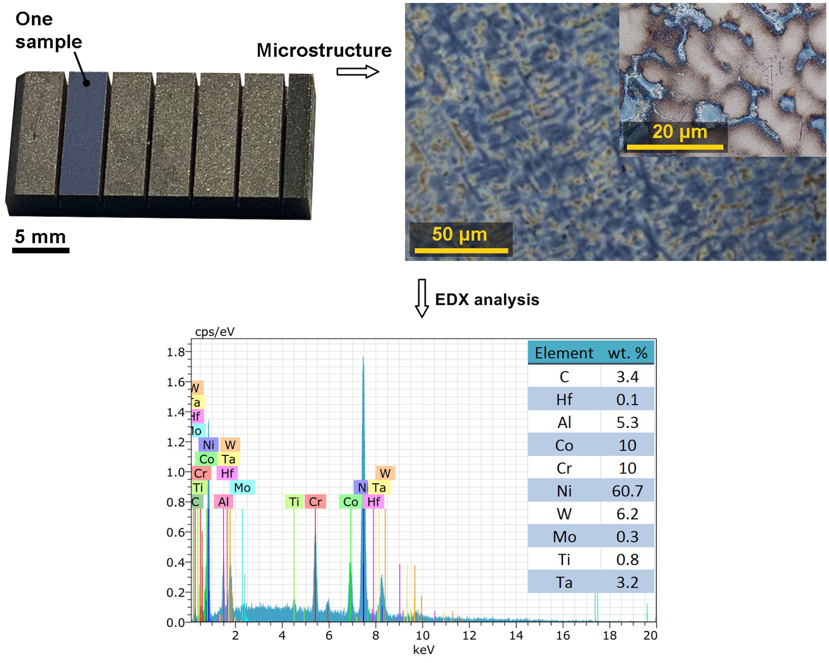
The example of produced samples for the third cut within the experiment and microstructure of the machined material Mar-M247 (LM).
WEDM machine setup
For the production of the experimental samples, a wire electrical discharge machine of the EU64 type from the Makino company was used, which was equipped with CNC control of all five axes and also a filling bath for dielectric liquid (deionized water), in which the material was immersed throughout the machining. The wire electrode was a brass wire of the CUT E type with a diameter of 0.25 mm from Penta Trading. The machining was performed using Multicut technology, the system of which was described, for example, in Mandal et al., 24 Huang et al., 25 or Patnaik et al. 26 studies. The offset between the first and second cuts was 180 µm and between the second and third cuts 130 µm, because significant cracks leading to coarse carbides were detected in this material after the first cut.
The purpose of the design of the experiment (DoE) is to investigate the influence of factors on the output variable – the process response and decide which of these factors, or which interactions of these factors are statistically significant and therefore significantly affect the monitored output variable. With a higher number of these factors, various factor designs are used, which can be used to reduce the number of investigated factors and thus more effectively find the most suitable regression model.
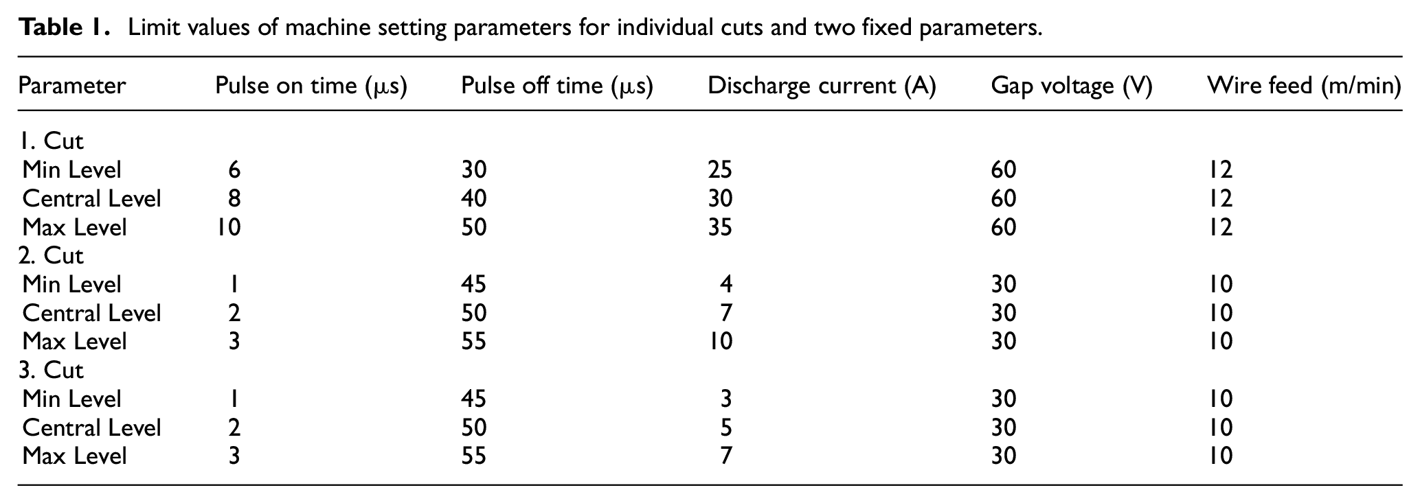
The design of the experiment performed in this study was based on monitoring the influence of three independent machine setting parameters, which were: pulse off time (Toff), discharge current (I), pulse on time (Ton), while gap voltage (U) and wire feed parameters (v) have been fixed. The limit values of these individual parameters for the individual cuts are written in Table 1 and have been determined on the basis of extensive previous tests 27 and the recommendations of the WEDM machine manufacturer.
Limit values of machine setting parameters for individual cuts and two fixed parameters.
The whole design of the experiment is actually a sequence of three partial experiments for individual cuts, where in the first two the cutting speed is maximized and in the third, the surface topography in the form of the parameter Ra is minimized. Face Centered Central Composite Design was always used with one replication of corner points and axial points and four repetitions in the center point. These repeated measurements are used to estimate the variability of the experiment. Since three parameters have been changed, eight corner points can be viewed as the vertices of the cube, and six axial points as the centers of the walls of this cube, as shown in Figure 2. To avoid systematic effects, the individual runs of the experiment were randomized.
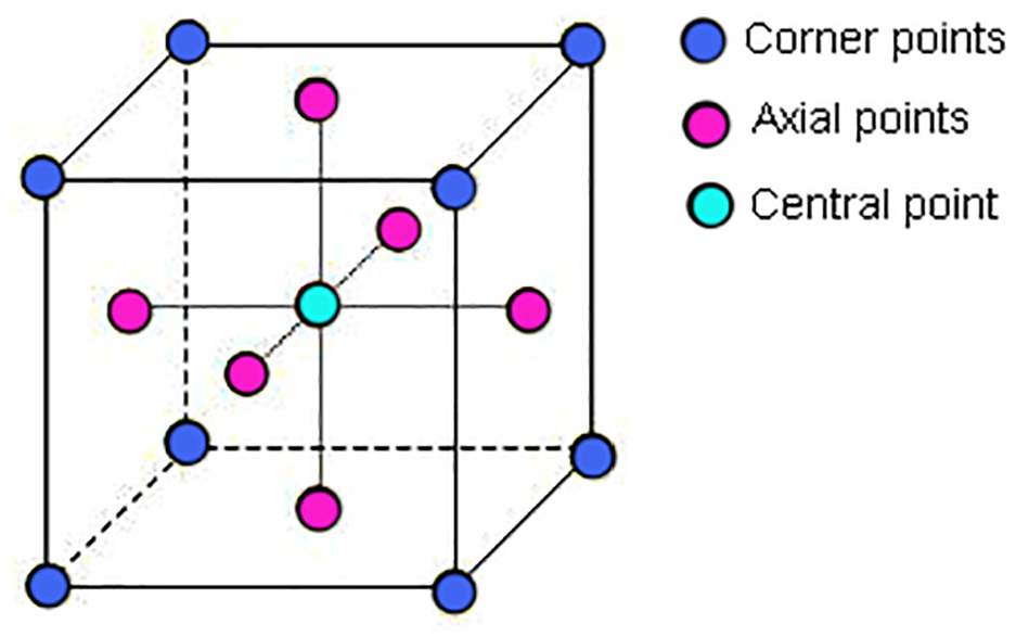
The face centered central composite design scheme used for all three sub-experiments.
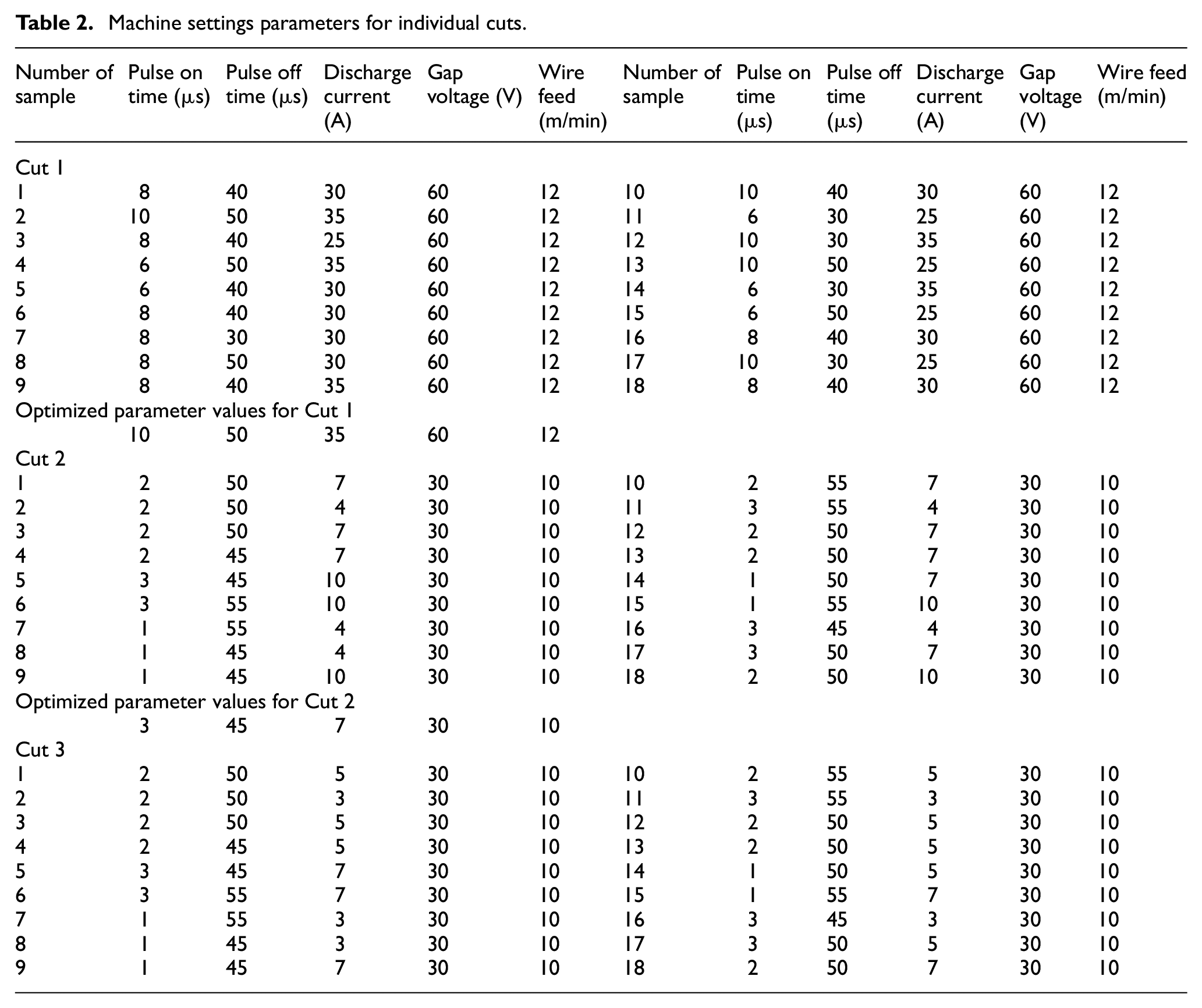
The machine setting parameters for individual cuts are given in Table 2. After performing the first part of the experiment for Cut 1, the optimal setting of the input parameters was calculated, which was used for Cut 1 of the following sub-experiments optimizing Cut 2 and 3. Similarly, after performing the second part of the experiment for Cut 2, the optimal setting of the input parameters was calculated, which was used for Cut 2 of the following sub-experiments optimizing Cut 3. The calculation of these optimal settings of input parameters for individual sections is given in Chapter 3.2.
Machine settings parameters for individual cuts.
Results and discussion
Experimental methods
All samples produced in the design of the experiment were blown with compressed air, cleaned in an ultrasonic cleaner, and further analyzed. A Lyra3-type electron microscope (SEM) from Tecsan was used to analyze the morphology and chemical composition, which was equipped with an energy-dispersive X-ray detector (EDX) to allow chemical composition analysis. The topography of all surfaces was analyzed using a contact 3D profilometer of the Dektak XT type from Bruker and subsequently processed in the Vision 64 program. 3D surface reliefs were also created using a 3D profilometer, however they were further analyzed using Gwyddion software. In order to be able to study subsurface processes and changes, metallographic preparations were created, which were studied by electron microscopy on Lyra3. Metallographic preparations were produced by common techniques – wet grinding and diamond paste polishing using the automatic preparation system TEGRAMIN 30 supplied by STRUERS. The final mechanical-chemical finishing was performed with the OP-Chem suspension also from the company STRUERS. The etching was performed using kalling’s 2 etchant (2 g of CuCl2 + 40 ml of HCl + 40 ml of ethanol) for 10 s. The microstructure of the samples was documented using an Axio Observer Z1m light microscope from Zeiss. The lamella for subsequent analysis in a transmission electron microscope (TEM) was manufactured in a Helios electron microscope from Thermo Fisher. The TEM used was of the Titan Themis 60-300 cubed type from Thermo Fisher.
Statistical evaluation of the cutting speed
The response that is optimized for the first and second cuts is the cutting speed v because at this stage it is primarily a matter of process efficiency. While in the third cut the surface topography is optimized and the cutting speed is monitored only as a secondary characteristic. The cutting speeds for all three cuts are shown in the graph in Figure 3(a). In the case of WEDM, the cutting speeds are set by the machine control system so that the tool does not come into contact with the workpiece. It is not possible to set them directly when programing the machine, as is the case with conventional machining techniques. However, the value of the current cutting speed can be read from the machine display during the machining process for each of the individual samples. The highest cutting speed in the first cut was achieved for Sample 2, namely 2.8 mm/min, which was machined with the parameters of the machine settings: U = 60 V, Ton = 10 µs, Toff = 50 µs, v = 12 m/min, and I = 35 A. On the contrary, the highest cutting speed was achieved in the second cut when machining Sample 17 (setting of machine parameters: U = 30 V, Ton = 3 µs, Toff = 50 µs, v = 10 m/min, and I = 7 A),namely 10.8 mm/min, while in Cut 3 this speed was further increased, specifically in the case of cutting Sample 5 to the value of 10.9 mm/min (the setting of machine parameters: U = 30 V, Ton = 3 µs, Toff = 45 µs, v = 10 m/min, and I = 7 A). These high cutting speeds were far from being achieved with multicut technology when machining Nimonic C 263 aviation alloy in Mandal studies.24,28 Even when machining the AA5083 aluminum alloy in the Selvakumar et al. 29 study, a speed higher than 8.9 mm/min was not achieved for the third cut. From this, it can be concluded that in our case much more optimal parameters of the machine settings could have been set than in the other studies mentioned above.
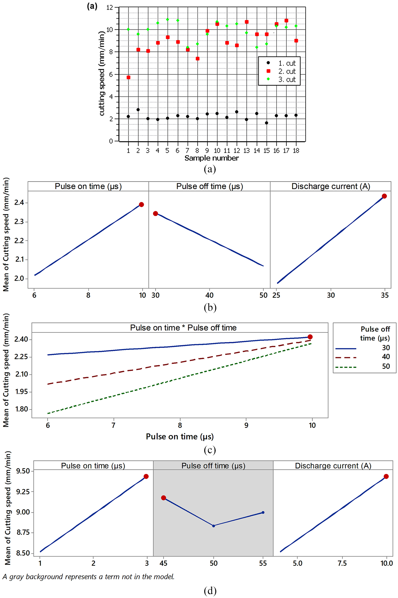
(a) Mar-M247 sample cutting speed for individual cuts, (b) main effects plot of the cutting speed of Cut 1, (c) interaction plot of the cutting speed of Cut 1, and (d) main effects plot of the cutting speed of Cut 2.
Cutting speed responses were always evaluated using regression analysis. Due to the chosen data collection plan, the full quadratic regression model was chosen, where in addition to the selected input factors there are their second-order interactions and their quadrates. Insignificant predictors were removed from this model using the Hierarchical Stepwise Selection method, where a significance level of 0.05 was chosen to remove and re-add the predictor, thus, there are only members in the model that are statistically significant. The models were adequate (p-valueLack-of-Fit >0.05), that is without statistically significant influence of other factors not included in the experiment.
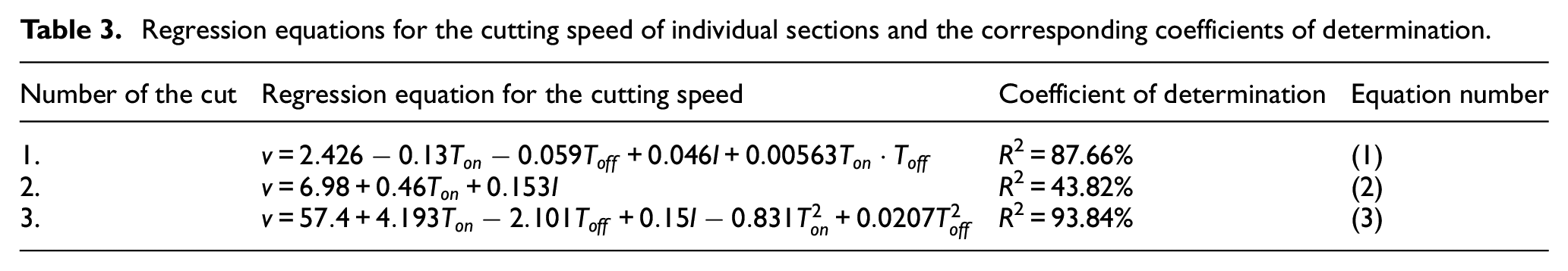
The coefficient of determination R2 indicates what percentage of the variability of the observed data is described by the given regression model. The regression equations for the cutting speeds of individual sections and the corresponding coefficients of determination are given in Table 3.
Regression equations for the cutting speed of individual sections and the corresponding coefficients of determination.
In the regression model of the cutting speed of Cut 1, all three input factors and the interaction of the TonToff times are significant, the effect of these factors is shown in Figure 3(b) and the interaction in Figure 3(c). The cutting speed is maximized. The Ton and I factors have a positive effect on the cutting speed, so they are set to maximum. The Toff factor has a negative effect, so it is set to a minimum. The TonToff interaction causes the effect of the Toff setting on the cutting speed to be much greater at Ton at the lower level than at Ton at the upper level. The optimal setting of the machine parameters for Cut 1 is in Graph in Figure 3(a) and (b) marked with red dots and numerically is given in Table 2. In the regression model of the cutting speed of Cut 2, only the factors Ton and I are statistically significant. The factor Toff and all interactions and squares are insignificant. Both important factors have a positive effect on the cutting speed as in Cut 1, so they are set to the maximum, as shown by the red dots in Figure 3(c). Factor Toff is statistically insignificant, but we have to set it somehow, so we chose the lower level, where the cutting speed is maximum. Numerically, the optimal setting of parameters for Cut 2 is given in Table 2. The cutting speed for Cut 3 is evaluated only as a secondary parameter and the effect of the parameters is similar to Cut 2, but the quadrates of both times (Ton and Toff) are also significant, the squares of the times appear as parabolic curvature in the Main effect plot shown in Figure 3(d).
Statistical evaluation of the sample surface topography
For the evaluation of the quality of machine parts, the analysis of the surface topography is indispensable, because the topography affects both the correct functionality and the efficiency, appearance, reliability, and service life of the manufactured parts. The development of new materials that have a higher strength-to-weight ratio leads to a reduction in the cross-sections of a number of components that are used in equipment operating under extreme loading conditions. These facts lead to the need to pay the increased attention to the possibility of operational failures, fatigue, the formation and propagation of cracks due to corrosion under stress, etc. Such failures are often affected by the nature of the surface – its topography, so its careful monitoring can prevent these problems. For this reason, two basic profile parameters, two profile parameters, and two of their surface equivalents were evaluated in the experiment. The evaluated parameters of the basic profile: Pa and Pz, the profile parameters: Ra and Rz, and the area parameters: Sa and Sz. All parameters were evaluated according to the corresponding standard for area parameters ISO 25178-230 and profile ISO 4287. 31 The topography parameters and 3D reliefs were evaluated using a Dektak XT profilometer, while the measurements were performed on each sample in five random places and subsequently arithmetic mean of the values was created.
The evaluated surface topography parameters of the individual samples were plotted and are shown in Figure 4. From these graphs, the trend of decreasing of all parameters of the topography with an increasing number of cuts is clearly evident, with the most significant trend being between the first and second cuts. Between the second and third, there was only a small improvement, which is still statistically significant. Because the setting of the experiment parameters for Cuts 2 and 3 differs only in the setting of the input parameter Discharge current and the order of the experiments was maintained, it was possible to perform a Paired t-test for individual characteristics of the surface topography. The difference between the mean surface topography in the form of the parameter Ra after Cut 2 and after Cut 3 is statistically significant(p-value = 0.003). Figure 5(a) shows the Boxplot of Differences of Ra after Cut 2 and Ra after Cut 3, as well as the 95% confidence interval for Mean of Differences, which does not contain a zero difference H0, thus graphically showing a statistically significant difference between the mean Ra values after the second and third circle. Furthermore, it can be seen from the figure that only 2 samples out of 18 had better Ra after Cut 2 than after Cut 3.
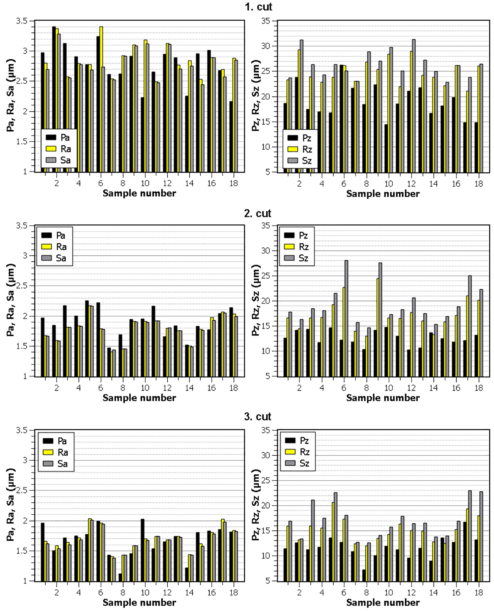
Evaluated topography parameters for individual samples and cuts: average height of profile (Pa), mean peak to valley height of primary profile (Pz), arithmetical mean deviation of profile (Ra), maximum height of profile (Rz), arithmetical mean height (Sa), maximum surface height (Sz).
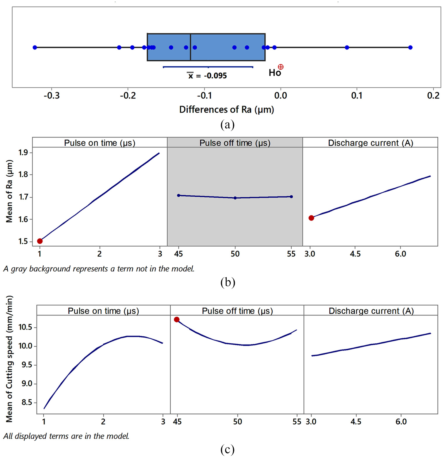
(a) Box plot of differences (Ra after Cut 3 – Ra after Cut 2), (b) main effects plot of Ra of Cut 3, and (c) main effects plot of cutting speed of Cut 3.
The lowest values of parameters were achieved in Sample 7, when after Cut 1 this sample had the value of Ra 2.5 µm, after Cut 2 Ra 1.4 µm and after Cut 3 equally Ra 1.4 µm. In the Patnaik et al. 26 study, where the topography after the individual cuts was also studied, a much more uniform improvement in roughness was achieved than in the case of this study. The reason could be the machining of a different material because Patnaik in his experiment dealt with the machining of a titanium alloy Ti-6Al-4V. Overall, however, the same Ra values of 1.4 µm were achieved after Cut 3. Similar values for surface topography after the first cut were obtained in the Bisaria and Shandilya32,33 studies.
As in the case of the cutting speed, regression models were created for the topography parameter Ra after individual cuts. Using the Hierarchical Stepwise Selection method, they were narrowed from the full quadratic regression model, as described in Chapter 3.2. Because we are mainly interested in the quality of the resulting surface, we will only present the model for the parameter Ra after Cut. This model has a coefficient of determination R2 = 90.68% and is adequate (p-valueLack-of-Fit = 0.298). The regression model itself is given by relation (4), which is:

The effect on the parameter Ra of these two important factors contained in the model is shown in Figure 5(b). Both factors cause the growth of Ra, which is undesirable and should be minimized. The parameter Toff is insignificant with respect to Ra, so we will use the secondary metric speed of cutting after Cut 3, which is maximized and therefore, Toff is set to the lower level. Optimal settings are marked with red dots. Furthermore, it is worth noting that except for the quadratic curvature, the Main effect plots for Ra (Figure 5(b)) and Cutting speed (Figure 5(c)) are the same and therefore with minimization of the parameter Ra the cutting speed deteriorates and by maximizing the cutting speed, Ra deteriorates.
3D reliefs each showing an area of 1 × 1 mm are shown in Figure 6. Due to the lowest evaluated parameters according to Figure 4, Sample 7 was selected for this analysis, while the effect after individual sections is clearly visible from the individual 3D reliefs, when a surface with lower and lower roughness was created. Not only did the roughness of the individual sections decrease, but also the individual craters were reduced, which is clearly visible thanks to the use of color filtering.
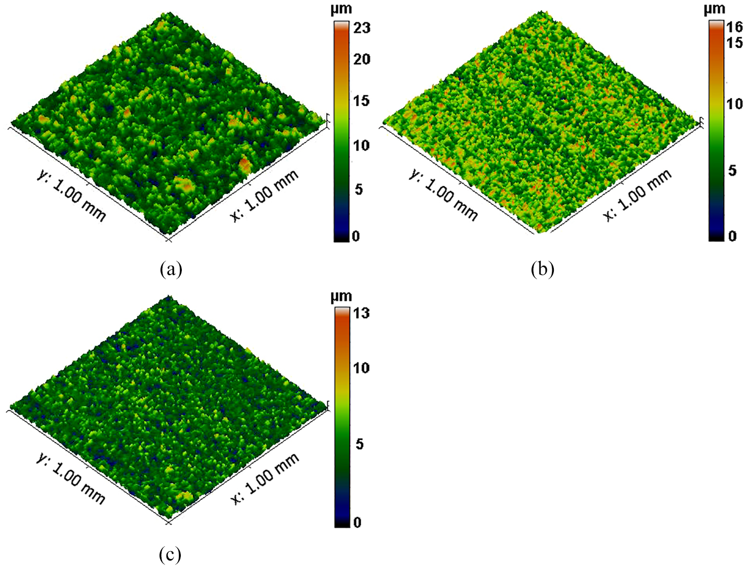
3D reliefs of the surface of Samples 7: (a) Cut 1, (b) Cut 2, and (c) Cut 3.
Morphology of machined surfaces, analysis of chemical composition and subsurface area
Electrically discharge machined surfaces have a special morphology, which is formed by a large number of craters occurring close to each other, but which are randomly distributed and therefore this type of texture is called random. The individual craters were created periodically with repetitive electrical impulses, which are necessary for the material separation process itself. The simulations of the formation of individual craters have been the subject of study in several publications, such as Schulze et al., 34 Shao and Rajurkar, 35 Tosun and Pihtili, 36 or Das and Joshi. 37 However, the size of craters and their appearance depends on many input factors, which are mainly the type of the machined material and its heat treatment, machine setting parameters, direction of the cut of the semi-product, etc. It is also possible to monitor the change of morphology in multicut technology when higher and higher quality of the machined surface is reached by individual cuts, which was presented, for example, in the study of Mandal et al. 24 or Huang et al. 25 The occurrence of surface and subsurface defects, which are relatively common in WEDM, has a significant effect on the quality of the machined surface, its correct functionality and predicted service life. These defects can only be found in the recast layer (completely melted and re-cooled layer of the material) or interfere with the base material. For this reason, it is always necessary to study not only the surface layer but especially the subsurface layer, in order to determine the depth to which cracks penetrated the material. A backscattered electron (BSE) detector was used for imaging in all cases, and the samples were always studied at a magnification of 1000x, 2500x, and then 4000x.
Figure 7 shows the morphology of two produced samples by Cut 1, namely Sample 11, which had the lowest values of topography parameters, and Sample 2, which had the highest values. From the morphological point of view, all samples produced were similar, there were no visible defects and the amount of recast layer was evenly distributed over the surfaces. From the chemical analysis of two places, the smooth bottom of the crater and the place with a high occurrence of the recast layer, it can be concluded that the contamination of elements from the wire electrode is significantly lower at the place of the smooth bottom of the crater. The surface contamination with wire electrode elements is a common phenomenon observed in most machined materials, such as Hardox 400 steel, 7 Creusabro 4800, 9 or Hadfield steel. 10 The only way to minimally minimize this contamination is with multicut technology, as found in the Huang et al. 38 or Jadam et al. 39 studies. The smooth bottoms of craters are covered with large amounts of oxides as well as carbon.
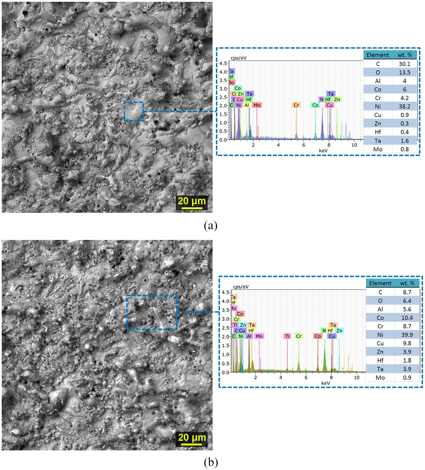
The surface morphology of samples after the first cut (SEM/BSE) including marking of the places where EDX analysis was performed and its final spectrum: (a) Sample 11 with machine setting parameters: U = 60 V, Ton = 6 µs, Toff = 30 µs, v = 12 m/min, and I = 25 A and (b) Sample 2 with machine setting parameters: U = 60 V, Ton = 10 µs, Toff = 50 µs, v = 12 m/min, and I = 35 A.
The morphology of the samples made in two cuts is shown in Figure 8, where there is a significant change in the appearance of the entire surface compared to samples machined with only one cut. The surface is generally significantly smoother, without large craters and an almost continuous recast layer as in Figure 7. Smooth places are again much less composed of diffused elements of the wire electrode. In addition, you can see small bubbles in the detail, which were formed in some places on the surfaces. Figure 8 shows the morphologies of two samples, with the highest topographic parameters, Sample 6 and the lowest ones Sample 7.
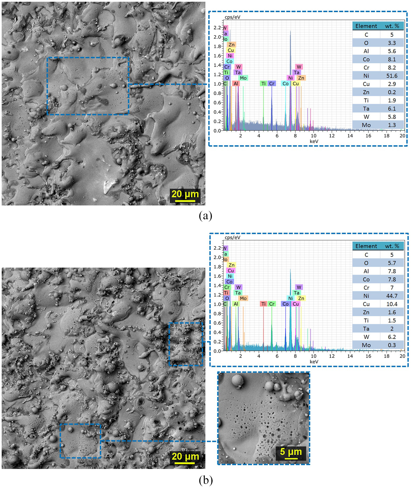
The surface morphology of the samples after the second cut (SEM/BSE) including the detail and marking of places where EDX analysis was performed and its final spectrum: (a) Sample 7 with machine setting parameters: U = 30 V, Ton = 1 µs, Toff = 55 µs, v = 10 m/min, and I = 4 A and (b) Sample 6 with machine setting parameters: U = 30 V, Ton = 3 µs, Toff = 55 µs, v = 10 m/min, and I = 10 A.
Samples made in three cuts again have a very similar morphology. Again, a sample with the lowest parameters of topography Sample 7 and Sample 6 with the highest parameters was selected for display. Their morphology, including area analysis of the chemical composition, is shown in Figure 9. It is clear that the diffusion has been largely eliminated and zinc has not been detected at all. The surface is covered with only a very small amount of carbon and oxygen.
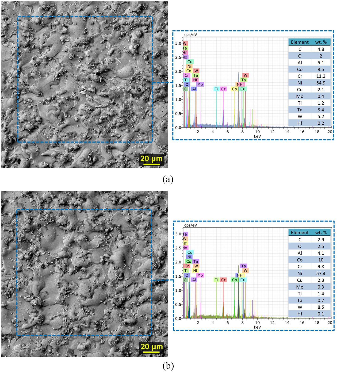
The surface morphology of the samples after the third cut (SEM/BSE) including the marking of places where EDX analysis was performed and its final spectrum: (a) Sample 7 with machine setting parameters: U = 30 V, Ton = 1 µs, Toff = 55 µs, v = 10 m/min, and I = 4 A and (b) Sample 6 with machine setting parameters: U = 30 V, Ton = 3 µs, Toff = 55 µs, v = 10 m/min, and I = 7 A.
Despite the fact that no defects (cracks) were found on the surface of the samples, it was necessary to perform the checking of the condition of the subsurface layer. For this reason, metallographic cross-sectional preparations of all samples were made and studied by electron microscopy on Lyra3, using a BSE detector at a magnification of 1000x and then 2500x and 4000x. From the study of the subsurface layer of the samples, it was found that the first cut contains a large number of subsurface cracks up to 10 µm in length, which lead through coarse carbides, which is visible in Figure 10(a) and (b). The cracks may also have a branched structure, as can be seen in Figure 10(a). Due to the length of each sample, which was 3 mm, about 10 such cracks were found on each of them without exception. From the images of the condition of the subsurface area of the samples with two and three cuts (see Figure 10(c)–(f)) it is clear that no cracks were present in these samples, despite the fact that the coarse carbides were again in close proximity to the machined surface. Thus, it can be said that the occurrence of cracks was completely eliminated thanks to the use of multicut technology. However, this is not the rule and, for example, when machining the titanium alloy Ti-6Al-4V in Patnaik et al. 26 and Jadam et al., 39 the cracks were not removed even after the third cut.
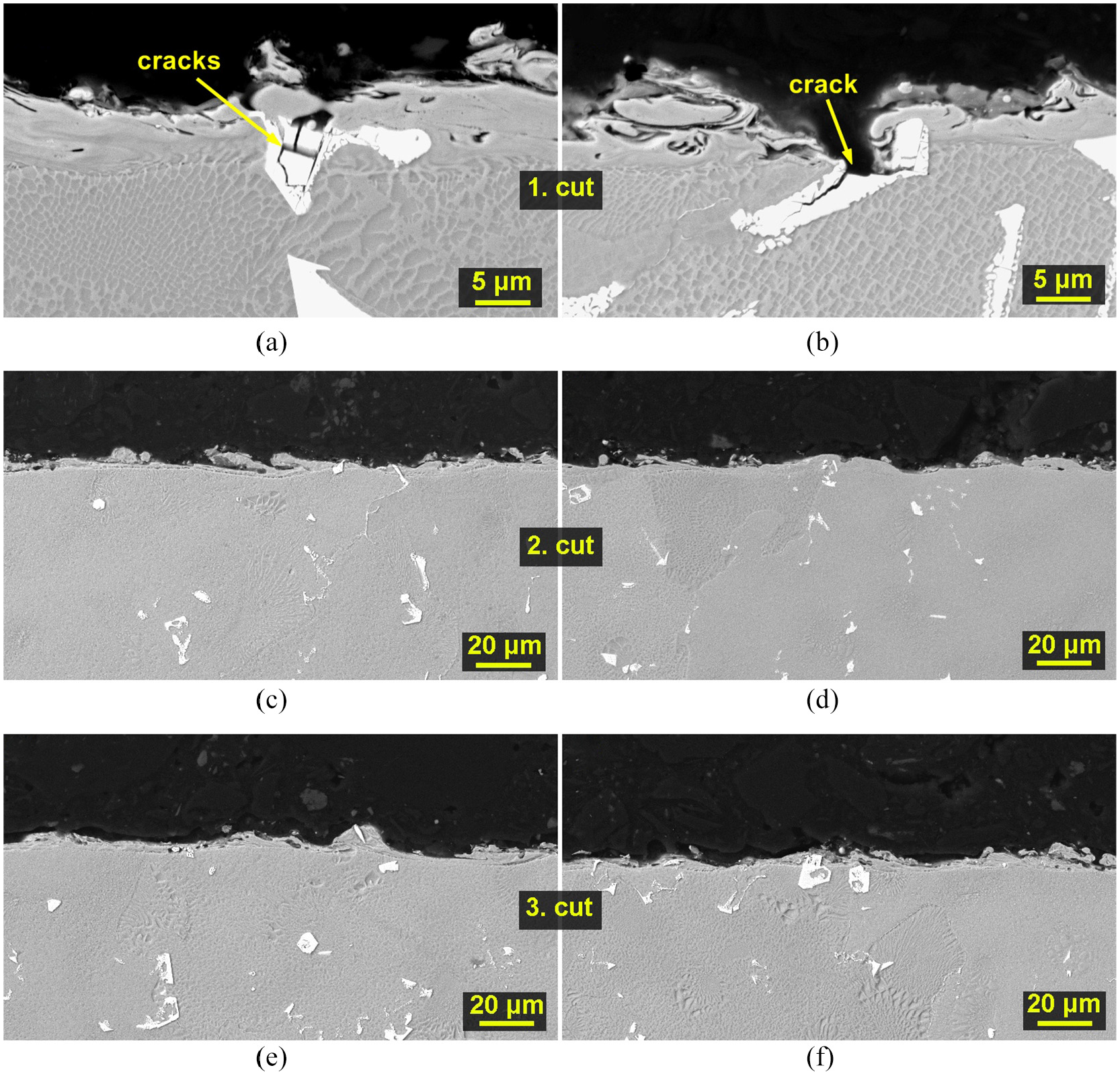
SEM/BSE sample cross-sections: (a) Sample 11 machined by the first cut with machine setting parameters: U = 60 V, Ton = 6 µs, Toff = 30 µs, v = 12 m/min, and I = 25 A; (b) Sample 2 machined with the first cut with machine setting parameters: U = 60 V, Ton = 10 µs, Toff = 50 µs, v = 12 m/min, and I = 35 A; (c) Sample 7 machined with the second cut with machine setting parameters: U = 30 V, Ton = 1 µs, Toff = 55 µs, v = 10 m/min, and I = 4 A; (d) Sample 6 machined with the second cut with machine setting parameters: U = 30 V, Ton = 3 µs, Toff = 55 µs, v = 10 m/min, and I = 10 A; (e) Sample 8 machined with the third cut with machine setting parameters: U = 30 V, Ton = 1 µs, Toff = 45 µs, v = 10 m/min, and I = 3 A; (f) Sample 6 machined with the third cut with machine setting parameters: U = 30 V, Ton = 3 µs, Toff = 55 µs, v = 10 m/min, and I = 7 A.
TEM lamella analysis
The lamella made of Mar-M 247 material from Sample 11 with machine setting parameters: U = 60 V, Ton=6 µs, Toff = 30 µs, v = 12 m/min, and I = 25 A was studied in terms of change in distribution and the content of individual chemical elements and the effect of machining on the crystal structure. The analysis was performed using a transmission electron microscope Titanat an accelerating voltage of 300 kV. EDX measurements were performed in scan mode (STEM) with a current of 1 nA to ensure a sufficient X-ray signal. The total measurement length was 10 min.
The lamella produced is shown in Figure 11, and two EDX measurements were performed, focusing on two areas. The EDX 1 scan focused on the heat affected area between the base material and the recast layer, which is formed by homogeneously distributed elements except for boron, iron, hafnium, and titanium, which have a higher concentration here, there is also copper and zinc originating from the wire electrode. In addition, separate particles consisting of aluminum, copper, hafnium, titanium, and tantalum have been found in this area. In the area of the recast layer, almost all basic elements had an increased concentration except for nickel, cobalt, molybdenum, and tungsten. The particles found at the interface of the recast layer and the base material were mainly made of aluminum. The increased concentration of tungsten in the upper part of the recast layer is caused by the use of tungsten as a protective layer during the production of the lamella. EDX 2 included a portion of the unaffected base material, and measurements show that in the base material, the individual elements are evenly distributed in the mixture except for cobalt, chromium, and to lesser extent tungsten which together form a venous structure separated by nickel. The high concentration of copper on the entire surface of the sample can be explained by the secondary transfer of electrode material during machining.
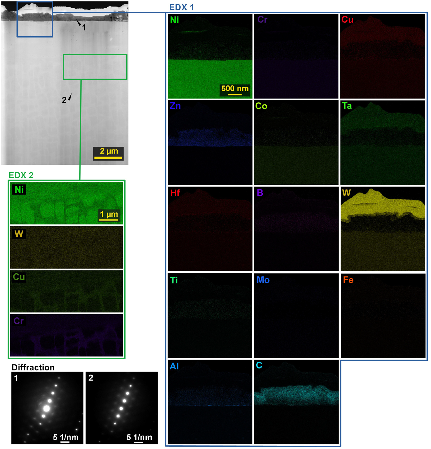
TEM lamella made of Mar-M247, including maps of distribution of individual elements in various details and diffraction patterns.
The impact of WEDM on the crystal lattice of the material was investigated in a diffraction image of a transmission microscope by taking two photographs in the middle of the base material and in the recast layer, as shown in Figure 11. To observe, it was necessary to change the microscope setting from scan to projection mode. The beam current changed from 1 to 10 nA to enhance diffraction. The comparison of diffraction patterns shows that due to machining there was only a slight change in interplanar distances by only 1%. There was an expansion in two-directional vectors and a reduction in one. This finding indicates slight residual stress.
Conclusions
In order to comprehensively study the multicut technology (Cut 1, 2, and 3) of the WEDM aerospace nickel superalloy Mar-M247, an extensive design of experiment of a total of 54 circles was performed, analyzing the effect of Pulse on time, Pulse off time, and Discharge current on the cutting speed and the quality of the machined surface, reaching the following conclusions:
-the highest cutting speed in the first cut was achieved for Sample 2 (machine setting parameters: U = 60 V, Ton = 10 µs, Toff = 50 µs, v = 12 m/min, and I = 35 A), namely 2.8 mm/min, on the contrary, the highest cutting speed was achieved in the second cut when machining Sample 17 (setting of machine parameters: U = 30 V, Ton = 3 µs, Toff = 50 µs, v = 10 m/min, and I = 7A), namely 10.8 mm/min, while in Cut3 this speed was further increased, specifically in the case of cutting Sample 5 (setting of machine parameters: U = 30 V, Ton = 3 µs, Toff = 45 µs, v = 10 m/min, and I = 7 A) to a value of 10.9 mm/min,
-pulse ontime and Discharge current factors have a positive effect on the cutting speed and increase it, therefore it is appropriate to set them to the maximum ranges monitored by us in all cuts, but in the case of the third cut, where the primary response was topography, it was found out that the cutting speed affects against the topography and it is more appropriate to set these parameters to the lower level,
-the lowest values of the topography parameters were achieved in Sample 7, when after the first cut this sample had the value of Ra 2.5 µm, after the second cut Ra 1.4 µm, and after the third cut – equally Ra 1.4 µm,
-the analysis of the cross-sections of the sample showed the occurrence of cracks up to 10 µm in length leading to coarse carbides on all samples made by only one cut, with about 10 such cracks on each sample (3 mm) without exception,
-no more cracks were studied on the samples machined with two and three cuts,
-TEM analysis of the lamella showed that the recast layer is formed by homogeneously distributed elements except for boron, iron, hafnium, and titanium, which show a higher concentration, there is also copper and zinc originating from the wire electrode.
-based on the above conclusions, it can be stated that the use of mutlicut technology will not only contribute to increasing the quality of the machined surface but also completely remove the cracks from the first cut. This knowledge will clearly contribute to increasing the life of manufactured parts and also to maintaining the competitiveness of WEDM technology.
Footnotes
Declaration of conflicting interests
The author(s) declared no potential conflicts of interest with respect to the research, authorship, and/or publication of this article.
Funding
The author(s) disclosed receipt of the following financial support for the research, authorship, and/or publication of this article: CzechNanoLab project LM2018110 funded by MEYS CR is gratefully acknowledged for the financial support of the measurements/sample fabrication at CEITEC Nano Research Infrastructure. This publication is a result of the project CACTU, Reg. No. CZ.02.1.01/0.0/0.0/17_049/0008397, which has been co-financed by European Union from the European Regional Development Fund through the Operational Programme Research, Development and Education. This project has also been financially supported by the Ministry of Industry and Trade of the Czech Republic which has been providing institutional support for long-term conceptual development of research organization. The project CACTU has been integrated into the National Sustainability Programme I of the Ministry of Education, Youth and Sports of the Czech Republic (MEYS) through the project Development of the UniCRE Centre (LO1606). This work was supported by the Brno University of Technology Specific Research Program, project no. FSI-S-17-4464.