
Abstract
Due to the poor processability of 0Cr17Ni4Cu4Nb stainless steel, the inserts are quickly worn down during the cutting process, affecting both the machining accuracy and surface quality of the machined part. In this study, the wear performance of four different types of coated inserts, TiCN+Al2O3, TiAlN, multilayer Ti composite, and TiCN+Al2O3+TiN, were investigated on the external turning of 0Cr17Ni4Cu4Nb stainless steel. The effects of different coatings on insert durability were analyzed from the perspective of wear profile, flank wear, and chip morphology. The wear of the inserts was mainly resulted from abrasive wear, diffusion wear, and adhesive wear. The flank wear ranking from the lowest to the highest for four coated inserts was TiAlN coating, TiCN+Al2O3 coating, TiCN+Al2O3+TiN coating, and multilayer Ti composite coating. The TiAlN coating deposited by physical vapor deposition exhibited excellent high-temperature oxidation resistance and stability, indicating its suitability for the turning of 0Cr17Ni4Cu4Nb stainless steel component. This study provides not only an important guidance for choosing inserts with different coating materials to improve wear performance, but also a good reference on the optimal design of indexable coated inserts for different materials.
Introduction
0Cr17Ni4Cu4Nb stainless steel is widely used in the aviation, petrochemical, and nuclear reaction industries, as well as various other fields, owing to its good mechanical properties and excellent corrosion resistance. 1 However, 0Cr17Ni4Cu4Nb stainless steel is known as a difficult-to-machine material, 2 which often leads to insert failure in the process of cutting 0Cr17Ni4Cu4Nb stainless steel. 3 The impact of insert failure on manufacturing has been becoming one of the key factors hindering improvements in production efficiency. 4 The common cause of insert failure is insert wear. Insert wear not only affects machining accuracy and surface quality of the machined part, but could also lead to the vibration and damage of the insert. As a result of that, insert wear has a direct impact on the success of the cutting process. 5 Changing the insert material is one way of improving the performance of an insert. The materials which might be able to meet production requirements for the insert are generally extremely expensive, and another alternative solution is to apply coating technologies. 6 Coating technologies deposit one or more layers of material on the insert substrate to increase its hardness, thermal stability, and wear resistance. 7 One or more layers of material are deposited by physical vapor deposition (PVD) or chemical vapor deposition (CVD) methods. 8 Thus various indexable insert coatings can be formed on the substrate to process difficult-to-machine material to improve wear performance at a relatively low cost.
Many studies have been mainly focused on improving insert life using different coating layers. Coating layers mainly include aluminum oxide (Al2O3), 9 titanium carbide (TiC), titanium carbo-nitride (TiCN), 10 titanium nitride (TiN), 11 and titanium aluminum nitride (TiAlN). 12 The insert life is correlated with the workpiece materials. Boing et al. 13 studied the insert life when turning different hardened steel. The results show that the insert with TiAlN coating layer by PVD method has better results in the turning of AISI 4340 steel, while the insert with TiCN/Al2O3/TiN coating layer using CVD method has better effects on the turning for AISI 52100 and D2 steels. Silva et al. 14 found that the wear resistance of inserts coated with TiAlN via PVD is better than that of TiCN/Al2O3/TiN by CVD method in the DDS machining. De Paiva et al. 15 obtained that the insert life coated with AlTiN by PVD method was approximately two times higher than TiCN/Al2O3 via CVD method during the machining of superduplex stainless steel. Sivaiah and Chakradhar 16 used the AlTiN PVD-coated insert to machine 0Cr17Ni4Cu4Nb stainless steel and found that adhesion and abrasion wear were the main failures of the insert.
To my knowledge, there is very limited research on the wear causing the insert failure. In this study, we investigated the wear performance of different coated inserts on processing 0Cr17Ni4Cu4Nb stainless steel. Four different types of coated inserts, TiAlN, multilayer Ti composite, TiCN+Al2O3, and TiCN+Al2 O3+TiN, were applied in the external turning. Insert wear profile, flank wear Bave, and chip morphology were analyzed. The insert wear modes were analyzed by the wear profile and the tool life was evaluated by the measurement of flank wear VBave. In addition, the wear mechanism of each coated insert was analyzed, thereby providing a foundation for discussing the applicability of the four coated inserts.
Materials and methods
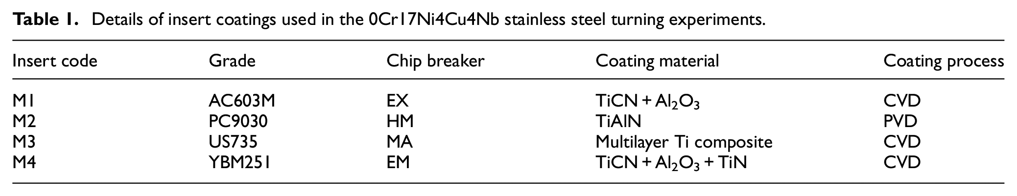
In this study, 0Cr17Ni4Cu4Nb stainless-steel bars were used as experimental specimens for their difficult-to-machine property and external turning experiments of 0Cr17Ni4Cu4Nb stainless steel were carried out under different indexable coated inserts. The indexable coated inserts were selected according to the properties and processing methods of 0Cr17Ni4Cu4Nb stainless-steel. Four types of coated inserts were selected and classified by their coating material, coating process, chip breaker, and grade as M1 to M4 shown in Table 1. The M1 insert was produced by Sumitomo Electric Carbide Inc with an EX-type chip breaker and is coated with TiCN and Al2O3 via CVD method shown in Figure 1(a). The M2 insert with HM-type chip breaker produced by Korloy Inc was coated with TiAlN by PVD method shown in Figure 1(b). The M3 insert with MA type chip breaker was produced by Mitsubishi Materials Corporation, which was coated with Multilayer Ti composite by CVD method shown in Figure 1(c). M4 insert, with EM-type chip breaker, was covered with TiCN, Al2O3, and TiN coating through CVD method, manufactured by Zhuzhou Cemented Carbide Cutting Tools Co., Ltd shown in Figure 1(d). All the coated inserts were installed on the tool holder and the model of the tool holder was MWLNR2525-M08, as shown in Figure 2.
Details of insert coatings used in the 0Cr17Ni4Cu4Nb stainless steel turning experiments.
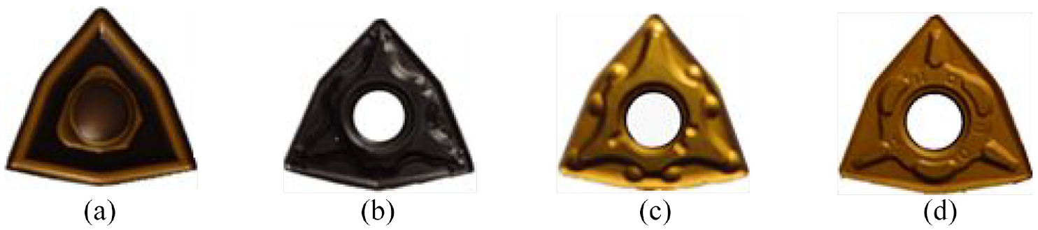
Four different indexable coated inserts: (a) M1, (b) M2, (c) M3, and (d) M4.
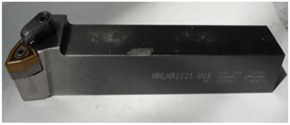
MWLNR 2525-M08 external turning tool holder.
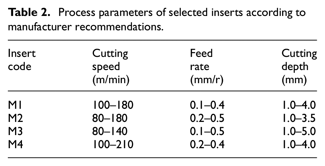
External turning experiments of the 0Cr17Ni4Cu 4Nb stainless steel were carried out under certain process parameters. The process parameters of external turning included the cutting speed, feed rate, and cutting depth. The initial set of process parameters was based on recommendation from the manufacturer and practical experience from other researchers. The parameter recommendation from the manufacturer helped us find the most effective and economical solutions to the 0Cr17Ni4Cu4Nb stainless steel turning problems. It also made it easier to eliminate time loss caused by unreasonable cutting speed, feed rates, and cutting depth. The recommended process parameters provided by the tool manufacturer for each corresponding insert were presented in Table 2. For the M1 insert, the recommended ranges of cutting speed, feed rate, and cutting depth were 100–180 m/min, 0.1–0.4 mm/r, and 1.0–4.0 mm respectively. For the M2 insert, the recommended cutting speed was between 80 and 180 m/min, the feed rate varied from 0.2 to 0.5 mm/r, and the cutting depth ranged from 1.0 to 3.5 mm. For the M3 insert, the recommended values for cutting speed, feed rate, and cutting depth were 80–140 m/min, 0.1–0.5 mm/r, and 1.0–5.0 mm, respectively. For the M4 insert, the cutting speed was between 100 and 210 m/min, the feed rate varied from 0.2 to 0.4 mm/r, and the cutting depth ranged from 1.0 to 4.0 mm. Xiao et al. 17 recommended the cutting speed from 120 to 140 m/min and found a cutting speed of 120 m/min was an optimal value for stainless steel turning. Elkaseer et al. 18 set the cutting speed at 120 m/min. Dinde and Dhende 19 investigated the turning of super duplex stainless steel and obtained the optimal combination of parameters for the cutting speed of 120 m/min and back cutting depth of 2.0 mm. Dudzik and Labuda 20 set a cutting depth of 2.0 mm in the turning process. Tekıner and Yeşılyurt 21 studied the turning of austenitic stainless steel with feed rate ranging from 0.2 to 0.3 mm/r and found the feed rate of 0.25 mm/r had the best results. Therefore, based on the manufacturer recommendation and practical experience from others, the specific cutting parameters used in the experiment were 120 m/min, 0.25 mm/r, and 2.0 mm for cutting speed, feed rate, and cutting depth respectively.
Process parameters of selected inserts according to manufacturer recommendations.
To investigate the influence of each coated insert on turning performance, the insert wear, flank wear VBave and chip morphology were studied. The insert wear was analyzed by JSM-6390A scanning electron microscopy (SEM) and energy dispersive spectroscopy (EDS). JGX-2 Large Tool Microscope was used to measure the flank wear VBave on the flank face of the insert. It was measured per 5 min from the beginning of turning process to the end, lasting for 30 min.
Results and discussion
In this section, indexable coated inserts wear, flank wear VBave, and chip morphology were investigated for the external turning of the 0Cr17Ni4Cu4Nb stainless-steel workpiece.
Indexable coated insert wear
It was found that the wear occurred on the rake face and flank face of the insert in the external turning process. The wear modes of the inserts were the coating layer peeling off, cutting-edge chipping, and crater wear of rake face, which resulted from abrasive wear, diffusion wear, and adhesive wear.
Wear on rake face
Wear on the rake face of four coated inserts was shown in Figure 3. It can be seen that wear on the rake face of the four inserts was mainly characterized by peeling of the coating material and some particles bonded to the surface, and scratching of the hard particles.
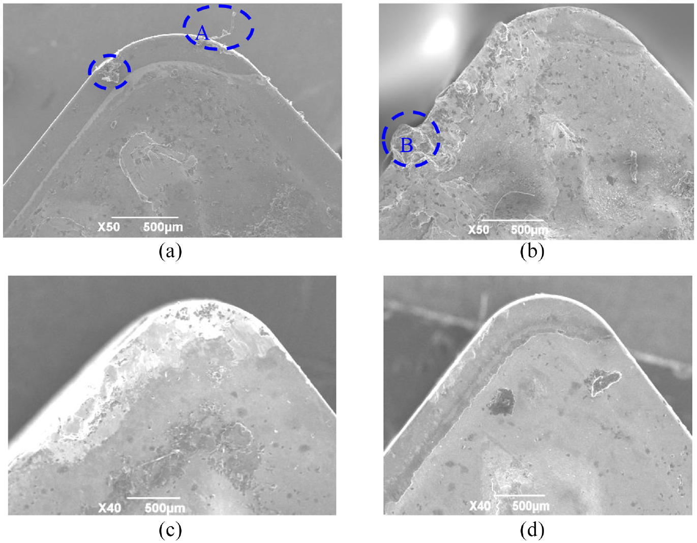
Wear on the rake face of the four different indexable coated inserts: (a) M1, (b) M2, (c) M3, and (d) M4.
The surface of the M1 insert has a small abrasion on the coated surface, and the main wear mode is the coating layer peeling off, which is a result of adhesive wear. Two obvious coating peeling phenomena can be observed near the cutting-edge in Figure 3(a). This may be because some workpiece material was stuck to the surface of the rake face under high stresses and temperature during the turning process. As a result of that, it leads to a buildup of material on the rake face. Some buildup was bonded to the rake face of the insert so strongly that small parts of the coating material could also be taken off when the buildup was large enough to be eventually carried away by flowing chips. The peeling phenomenon in region A of the M1 insert (Figure 3) was quite evident shown in Figure 4. When the coated surface of the insert was peeled off, the exposed cemented carbide substrate continued to be scratched and rubbed by the hard abrasive particles from the 0Cr17Ni4Cu4Nb stainless-steel workpiece, leading to further abrasive wear.
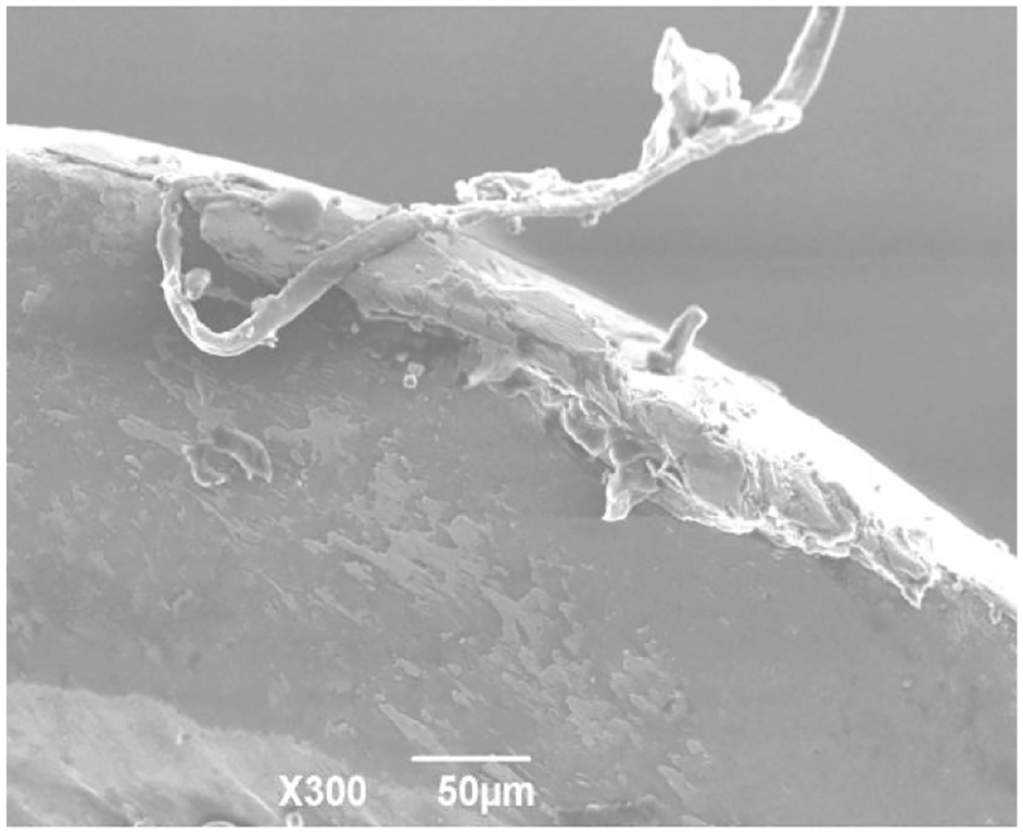
Coating peeling of M1 insert.
The M2 insert was mainly subjected to adhesive wear. A large amount of workpiece material can be seen adhered to the rake face, and there was relatively less wear at the cutter point in Figure 3(b). To further analyze the wear of the M2 insert, the region 001 in the region B was selected for the analysis of the energy spectrum. Figure 5 showed the energy spectrum analysis of the region 001. It can be seen that the elements of nickel, chromium, and copper were detected, which was consistent with the main chemical composition of 0Cr17Ni4Cu4Nb stainless steel. The contact between the chips and rake face made it possible for the elements of nickel, chromium, and copper from stainless steel to diffuse into the rake face at high temperatures. The diffusion changed the original chemical compositions of the insert, accelerated the wear of the rake face, and lowered the cutting performance. In addition, the buildup formed on the surface of the insert was eventually carried away when it became large enough as the turning continued, resulting in part of the insert material being taken away as well.
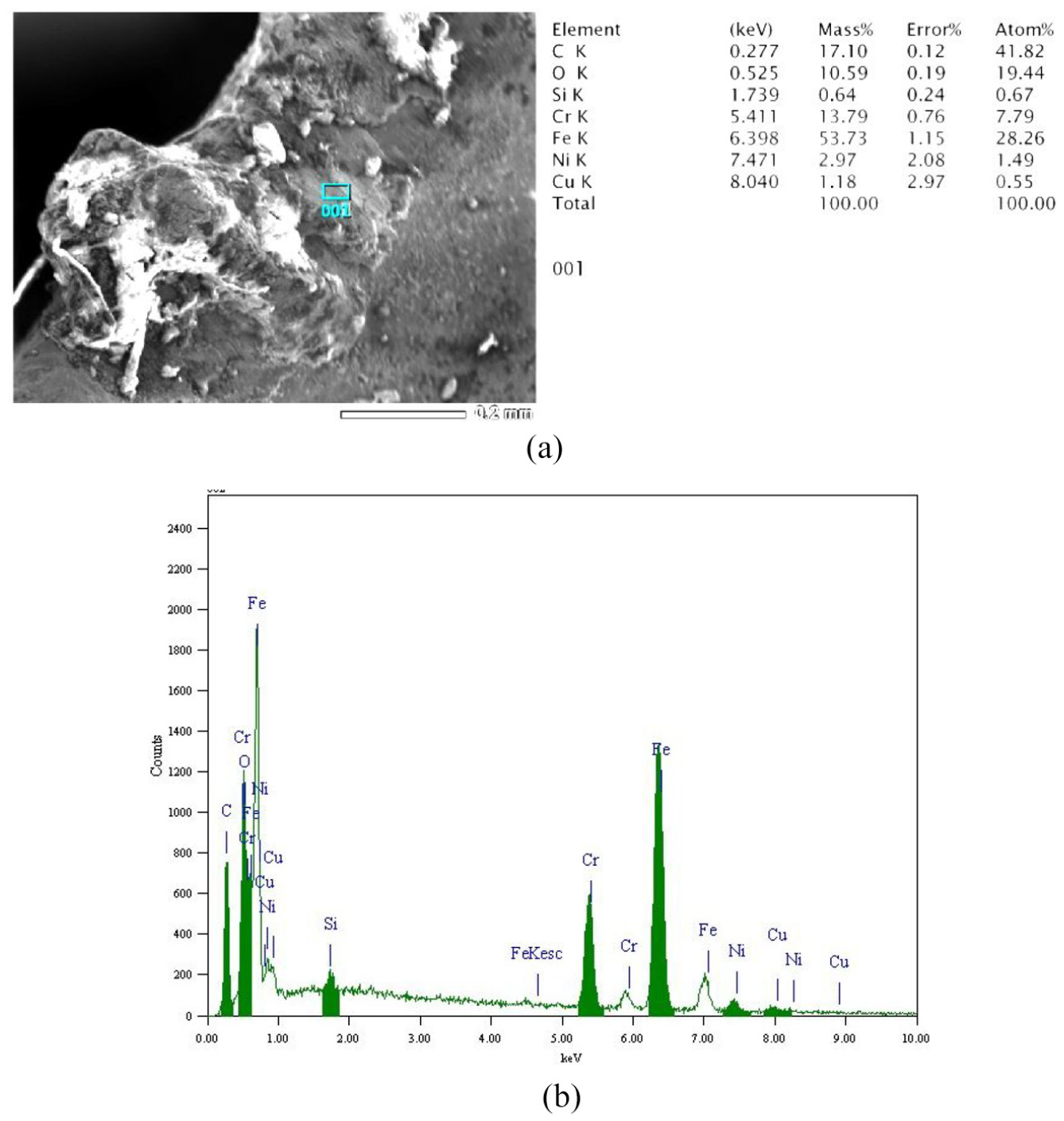
Energy spectrum analysis on rake face of M2 insert: (a) EDS of point 001 on the M2 insert and (b) Region 001.
The surface of the M3 insert showed many bright white areas and large amounts of material loss at the cutting edge and cutter point in Figure 3(c). Cemented carbide substrate can be observed at the cutting edge of the insert after the coating was peeled off. The cemented carbide substrate was also subjected to severe abrasive wear. This was because 0Cr17Ni4Cu4Nb stainless steel underwent hardening during the turning process, and the formed hardened layer caused severe wear on the cemented carbide substrate. The M4 insert clearly showed peeling of the coating and sticking particles on the rake face, as well as slight scratches on the cutting edge in Figure 3(d). It was caused by the adhesive wear and abrasive wear.
Wear on flank face
Wear on the flank face of the different coated inserts was shown in Figure 6. It included boundary wear, notch wear, spalling, and adhesive wear. The M1 insert showed notch wear and abrasion wear. The grooves can be seen on the flank face due to the abrasion between the insert and workpiece. The cutting edge of the M2 insert has obvious adhesion wear, and also localized bonding on the solid surfaces of the insert can be observed shown in Figure 6(b). There is no obvious wear or scratches on the flank surface of the M2 insert. The flank face of the M3 insert has severe spalling and large scratches shown in Figure 6(c). The cutting edge of the M3 insert close to the maximum cutting depth was peeled off. Wear of the flank face of the M4 insert was similar to the wear observed on the M1 insert shown in Figure 6(d), including significant scratches on the flank face. But the bright white area near the cutting edge is larger compared to the same area on the M1 insert. This was caused by an extra layer of TiN coating for M4 insert, resulting in its lower wear resistance than the M1 insert.
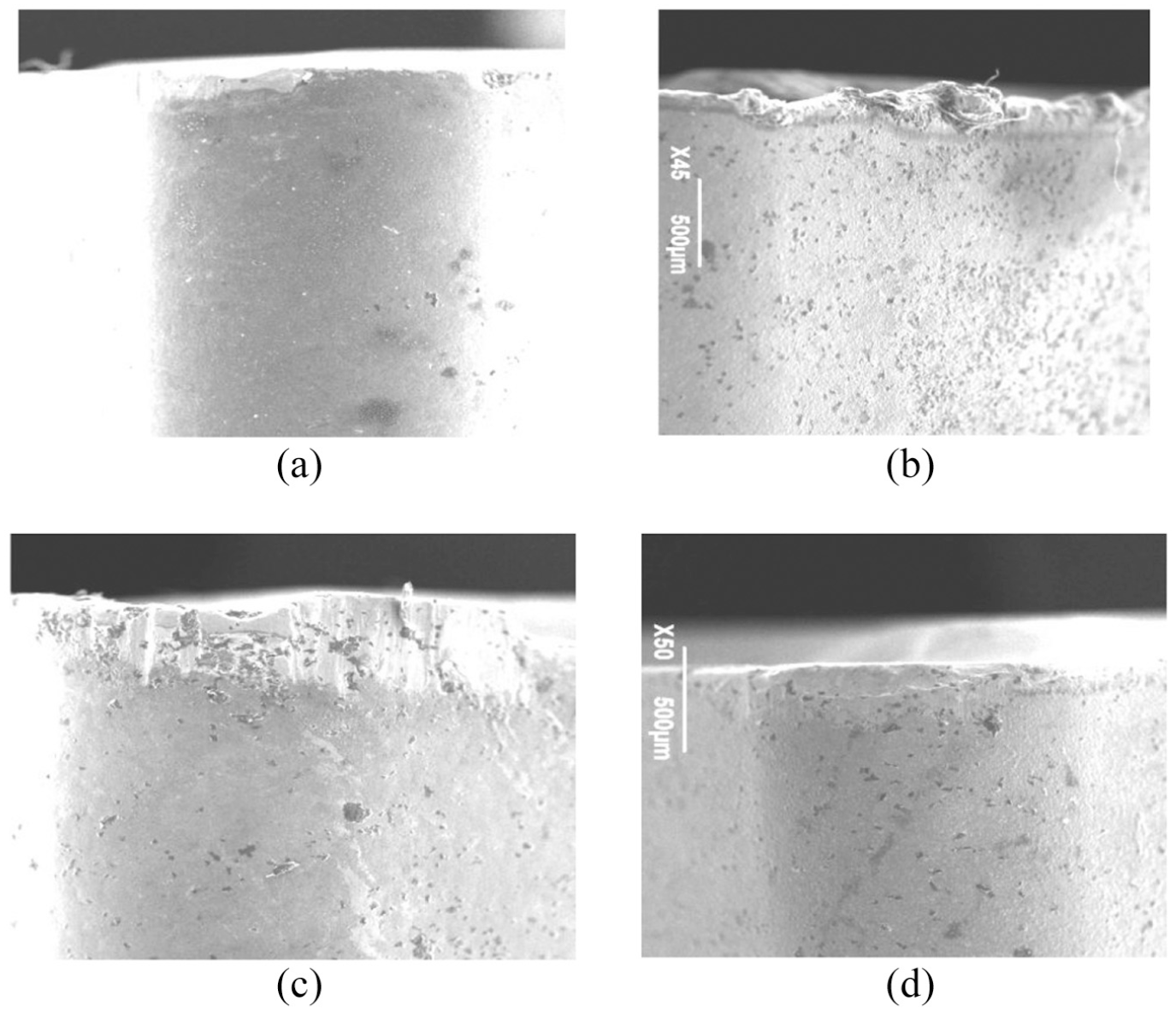
Wear on the flank face of each indexable coated insert: (a) M1, (b) M2, (c) M3, and (d) M4.
Flank wear VBave measurement
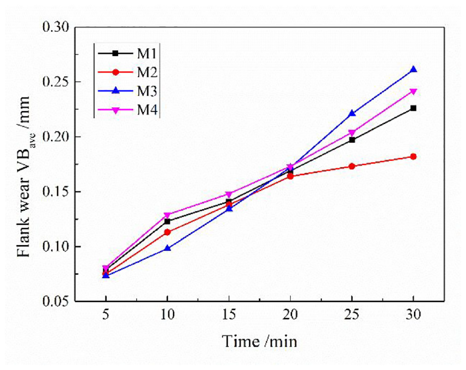
According to the ISO international standard, the insert life criterion of the flank wear VBave was 0.30 mm. The flank wear VBave of the four indexable coated inserts are presented in Table 3. The flank wear VBave was plotted as turning time versus flank wear loss for each insert, as presented in Figure 7.
Flank wear VBave of each indexable coated insert.
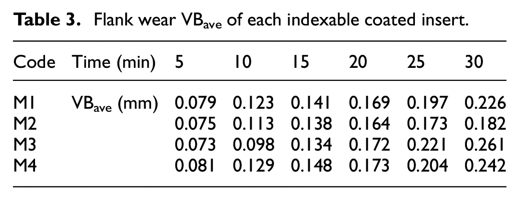
Flank wear VBave of each indexable coated insert.
Within the first 15 min of external turning, it was observed that the rank of the flank wear VBave for four different inserts from the lowest to the highest was M3, M2, M1, and M4. This was because the multi-layer titanium composite coating on insert M3 had high hardness, so it tended to resist the wear better at the initial stage of the external turning when the tool temperature were relatively low. Flank wear VBave of the M2 insert was slightly higher than that of M3 insert, but lower than the insert M1 and M4 because the hardness of TiAlN layer was higher than the Al2O3 layer and TiN layer in M1 and M4. Therefore, at the initial stage of mechanical friction, harness played a critical role in wear resistance.
After 15 min, flank wear VBave of the M3 insert increased sharply, and became the largest wear among the four inserts after 20 min. New order for the flank wear VBave from the lowest to the highest was M2, M1, M4, and M3. As the turning process time increased, the temperature of the tool surface kept increasing. Both the hardness and stability of the insert at the high temperature became the main factors to affect the flank wear VBave. This might be the reason why M2 insert coated with TiAlN showed minimal flank wear and M3 insert exhibited maximum wear among four inserts. The high temperature made it possible for Al in the TiAlN coating to diffuse outward during the turning process and react with oxygen to form a dense and complete Al2O3 protective film, which prevented further oxidation of the coating and greatly improved the stability of the TiAlN coating. Although its hardness is slightly lower than that of multilayer Ti composite coating, it still showed an ideal cutting effect. Compared to the rate of wear of the M1 insert, the M4 insert showed faster wear. This was because the top layer TiN coating of the M4 insert had lower hardness and underwent abrasion wear and adhesive wear until the Al2O3 layer in the middle was exposed to slow down the wear. Meanwhile, Al2O3 was the top layer of the M1 insert and exhibited better wear resistance at high temperature environments than the M4 insert.
Chip morphology
Figure 8 showed the chip morphologies generated by each indexable coated insert during the turning process of 0Cr17Ni4Cu4Nb stainless steel. All chips produced by the coated inserts were taupe-colored C-type chips. The chip morphology among four different inserts showed very slightly different, indicating the low possibility of difference caused by the wear. All inserts exhibited less wear on the flank face during the turning process. Although peeling, spalling, and adhesive wear were observed on the rake face, they did not have a great impact on the chip breaking performance.
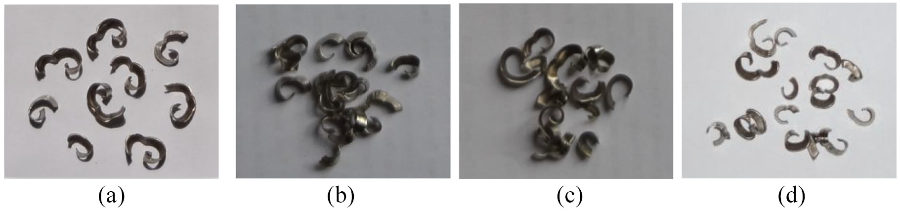
Chip morphologies produced by inserts M1 to M4: (a) M1 insert, (b) M2 insert, (c) M3 insert, and (d) M4 insert.
The analysis of wear resistance of inserts
Effect of coating material
The influence of the coating material on wear resistance mainly depends on the hardness, thermal stability, oxidation resistance, chemical stability, and anti-blocking ability of the material.
The thick Al2O3 surface coating on the M1 insert had high hardness, excellent chemical stability, and good high-temperature oxidation resistance. The coating was effective against oxidation wear, crater wear, and thermoplastic deformation. However, the M1 insert exhibited significant peeling of coating layer and bright white wear areas during the turning tests.
The TiAlN coating on the M2 insert demonstrated the best wear resistance during the turning test. TiAlN not only had high hardness, but also exhibited excellent stability and oxidation resistance under high temperatures. At the early stage of turning, the aluminum oxide was not able to be formed on the TiAlN coatings, which lead to relatively faster tool wear. After processing for a period of time, the TiAlN coating showed good wear resistance, which might be a result of the possible formation of Al2O3 film on top of the coating to slow down the wear. This is why it was often used in semi-finishing and roughing environments in which a huge amount of cutting heat was generated.
The M3 insert was coated with multilayer Ti composite, of which the main components were Ti, C, and N. Since both TiC and TiCN had high hardness, the M3 coating had the highest hardness among the four coating materials and exhibited excellent wear resistance during the initial stage of processing. However, as the temperature increased, the coating was quickly peeled off due to the adhesive wear.
The M4 insert was coated with TiN, which had the lowest hardness out of the four surface coatings examined in this study, and the coating was quickly worn out during the initial cutting stage, and more wear can be observed on the flank face compared to the other three inserts. However, the TiN coating had excellent anti-blocking properties and no serious bonding phenomenon occurred during the turning process.
Effect of coating method
The M1, M3, and M4 inserts had multi-layer coatings that are deposited onto the insert via the CVD process, whereas the M2 insert had a single-layer coating deposited using the PVD process.
The coating on the M1 insert had a double-layered structure. First, a layer of TiCN was deposited on the cemented carbide substrate, subsequently a thick layer of Al2O3 was deposited on top of it. The TiCN coating formed a multi-layered structure by continuously altering its C and N content, which can reduce internal stress in the coating material and improve the bonding forces between elements. Therefore, it was often used as the underlying coating material in CVD coating. The Al2O3 coating showed low thermal conductivity and good high-temperature performance and can effectively prevent the underlying tool substrate to be affected from the high cutting temperature on the top layer. The thick Al2O3 coating exhibited excellent thermal insulation, particularly in high-temperature environments.
The multilayer structure of the M3 insert coating layer included Ti, C, N, and very small amount Fe without any other impurity elements. The TiC layer was bottom layer next to the substrate, then the TiCN intermediate layer, and the TiN top layer. The multilayer structure had lowered internal stress between the different coating layers, and also between the coating layer and substrate. The relatively low internal stress within the coating can effectively improve its adhesion strength and increase both its hardness and toughness.
The coating on the M4 insert consisted of a layer of TiCN that adheres to the cemented carbide substrate with a thin intermediate layer of Al2O3, and finally, a layer of TiN was applied to the top. The wear resistance of the M4 insert coating was similar to that of the M1 insert coating, but the lifespan of the M1 coating was slightly better.
The M2 insert is coated with a single layer of TiAlN. The biggest structural difference between the PVD and CVD coatings was that the PVD process resulted in a relatively thin coating not adhering to the underlying substrate very well. As the thickness of the coating increased, overall wear resistance of the coating improved, however, the increase in thickness also increased the residual stress between coatings. Excessive residual stress can reduce the strength of the material and may lead to cracking.
In summary, the TiAlN coating deposited by PVD offers better wear resistance compared to the other three coatings deposited by CVD. Among the three CVD-coated inserts, the M1 insert had a thicker Al2O3 coating offering the best wear resistance, followed by the three-layered M4 coating. The multi-layered M3 insert composed of multilayer Ti composite had the lowest wear resistance under high-temperature environments.
Conclusions
In this study, the wear performance of four types of indexable coated inserts was studied during external turning of 0Cr17Ni4Cu4Nb stainless steel. Based on both theoretical and experimental analyses, the following conclusions can be made:
The main forms of insert wear that occur while cutting 0Cr17Ni4Cu4Nb stainless steel are abrasive wear, diffusion wear, and adhesive wear.
All chip morphologies are taupe-colored C-type chips. The coated material has little impact on the chip morphology.
TiAlN coatings deposited by PVD have excellent high-temperature oxidation resistance and stability which is more suitable for semi-finishing of 0Cr17Ni4Cu4Nb stainless steel components among four different studied inserts.
The results of this work provide an important guidance for the selection of coated inserts in actual production processes and optimal design of indexable coated inserts.
Footnotes
Declaration of conflicting interests
The author(s) declared no potential conflicts of interest with respect to the research, authorship, and/or publication of this article.
Funding
The author(s) disclosed receipt of the following financial support for the research, authorship, and/or publication of this article: This research was funded by Natural Science Foundation of the Shaanxi Province of China (Grant No. 2018JQ5002).