
Abstract
Widespread application of ball end milling operation is an outstanding characteristic in the field of manufacturing of die and molds. Tool inclination angles, which could improve the cutting performance of ball end mill, are critical factor in the ball end milling process, and also chip formation is one of the most important phenomena in the machining process. Numerical simulation, geometric analysis, observation by optical microscope and scanning electron microscope, and energy-dispersive spectroscopy analysis were adopted to study the chip formation during ball end milling of H13 die steels involving tool inclination angles in this work. The theoretical uncut chip geometry and tool–work contact zone were analyzed by computer-aided modeling technology. Finite element modeling of chip formation process involving tool inclination angles was performed, and variations of the maximum chip temperature which could provide assistant understanding of practical chip formation were analyzed. This article also investigated the practical chip morphologies, chip color, and the cutting characteristics under different process conditions and tool inclination angles. The optical microscope and scanning electronic microscope were used to capture the micro-photos of the chips under different process parameters, and the chip color and chip morphologies were discussed together with the cutting characteristics with regard to various process parameters. Energy-dispersive spectroscopy analysis of the chip free surface and back surface was also carried out for some special tool inclination angles. Deep understanding of the chip formation in multi-axis milling process was enhanced, and the research work could provide support for the selection of process parameters to some extent.
Keywords
Introduction
Ball end milling process is widely used to remove materials for complex three-dimensional (3D) surface manufacturing in some fields such as die and molds. The tool inclination angles are generally used in the multi-axis ball end milling process, and the machining performance could be significantly improved using the inclination angles. Chip formation is one of the most important phenomena in the machining field, 1 which is critical to the better understanding of the cutting process and prediction of cutting forces. Many researchers have paid attention to the chip analysis for milling process.
Milling process is the most widely used machining operation, and the following research works involve different milling modes concerning the chip features and formation process. Fromentin and Poulachon 2 focused on the thread milling process, and the uncut chip thickness for internal thread milling was calculated to model the cutting forces. Mian et al. 3 studied the minimum chip thickness by means of analyzing acoustic emission (AE) signals with regard to micro-milling process. Spiewak 4 proposed an improved model for chip thickness, and the model’s sophistication was increased by combining the essential characteristics of the previously developed models in order to improve the accuracy and reliability. Pu et al. 5 developed an algorithm for instantaneous uncut chip thickness using nonuniform rational B-spline (NURBS) helix for peripheral milling. They used the NURBS helix to characterize the contact cutting edges between the cutter and workpiece and chip thickness curve, and the instantaneous uncut chip was built as ruled surfaces with the two special curves. Tang et al. 6 investigated the effects of cutting speed on the chip morphology for peripheral milling process with conventional and high cutting speed, and cutting forces, effective stresses, and temperature in deformation zone were also discussed. Ekinovic et al. 7 investigated the chip formation process and chip geometry of high-speed milling hardened steels in order to make a trade-off with regard to the machining performance and cost. Wan and Zhang 8 presented a model for calculating the instantaneous undeformed chip thickness concerning the tool–workpiece deflection and the immersion angle variations in end milling of flexible workpiece. Toh 9 studied the effects of depth of cut, tool condition, and milling modes on the chip surface temperature of high-speed rough milling of hardened steels with ultrafine grain tungsten carbide corner radius end mills, and temperature was measured by an infrared red technique. Also, the chip color and micrograph were discussed. Wang et al. 10 investigated the slot micro-milling of Al6061-T6 by means of finite element (FE) method, and the tool–chip contact length, chip angular acceleration, and chip moments were analyzed. The scanning electron microscope (SEM) images of the experimental chip were also discussed.
The face milling process is also a popular research field, and the following works are concentrated on face milling. Shaw and Vyas 11 focused on the chip formation of face milling of hardened steel with polycrystalline cubic boron nitride, and cyclic saw tooth chip was analyzed. Zheng et al. 12 studied the influence of tool run-out on the undeformed chip thickness to predict the milling forces during face milling process, and both the radial and axial offsets of the insert tip to the datum point were considered to model the tool run-out effects. Pittalà and Monno 13 investigated the chip formation process for face milling operation using 3D FE simulation method, and modeling of insert geometry and sensitivity analysis of friction model was carried out in the simulation. Also, the cutting forces measured during practical cutting tests were used to validate the FE model.
Ball end milling is widely used to generate complex surface, and the following examples show the relative analysis of the chip features induced in ball end milling operation, which is mainly about three-axis milling process. Jung et al. 14 proposed a calculation algorithm for chip load of cutting edge, and mathematical analysis of exact chip engagement surface was conducted. Sonawane and Joshi 15 predicted the instantaneous chip dimensions including the chip length, width, and thickness, and the corresponding instantaneous shear angle was also calculated in order to predict the cutting forces of ball end milling of Inconel 718. Soo et al. 16 studied the chip formation process of three-axis high-speed ball end milling using FE modeling method, and the actual chip was also given to validate the simulation result. Liu and Loftus 17 studied the surface topography considering the trajectory of single flute using surface generation and material removing algorithm, and the chip geometry definition was also analyzed for three-axis ball nose end milling process. Ning et al. 18 focused on the chip formation induced by three-axis ball end milling process, and the effects of chatter behavior on the chip were also analyzed. Tsai and Liao 19 predicted the cutting forces for three-axis ball end milling using geometrical analysis, and the undeformed chip thickness and chip formation characteristic were also discussed. Bouzakis et al. 20 investigated the chip cross section and undeformed chip thickness in ball end milling by mathematical procedures, and the influence of tool inclination angles on the chip formation was considered. Liang and Yao 21 modeled the instantaneous chip thickness of five-axis ball end milling under finish machining condition using engagement boundary chip model, and the result was validated by comparing the chip volume with the data measured with the commercial software. Feng and Menq 22 presented the undeformed chip thickness distribution along the cutting edges in ball end milling process, and the effect of cutter axis offset and tilt on the undeformed chip geometry was also considered. Lazoglu and Liang 23 expressed the undeformed chip thickness in ball end milling for modeling the cutting forces. Yang and Park 24 developed a cutting force model treating the cutting edge as a series of infinitesimal elements, and the cutting process corresponding to each element was processed as an orthogonal cutting process in the plane containing the cutting velocity and chip flow direction. Fontaine et al. 25 involved the local undeformed chip section in the modeling of cutting forces for ball end milling with tool–work inclination angles. Wei et al. 26 presented the instantaneous chip thickness of the engaged cutting element in the prediction of cutting forces for three-axis ball end milling of sculptured surface with Z-level contouring tool path.
There are many published articles concerning chip geometry analysis for ball end milling process based on mathematical modeling, but investigations on the chip derived from the multi-axis ball end milling operations are rarely reported. The chip inevitably suffers the mechanical load, such as cutting force, compression, and friction, and the thermal load, such as heat, temperature, and heat flux transferred into the chip, during the practical cutting process, and so the geometry and morphology of the actual chips are different from the theoretical analysis under ideal condition. Hence, the research about the actual chips generated by practical ball end milling experiments is necessary. However, the reported works on the actual chips, especially the actual chips produced by multi-axis milling process, from several perspectives are limited. This work concentrated on the chip formation process and chip features for ball end milling process concerning the tool inclination angles in order to deepen the understanding of chip formation mechanism. Numerical simulation, geometric analysis, observation by optical microscope and SEM, and energy-dispersive spectroscopy (EDS) analysis were adopted to study the chip formation during ball end milling process involving tool inclination angles in this work. Better explanations are given to recognize the chip formation induced in machining process involving various tool inclination angles using ball end mill. With the help of studying the chip formation process, the effects of tool inclination angles on cutting conditions, such as the tool tip engaging in the cutting process or not, posture of the engaged cutting edges, and the effective cutting speed, could be better understand to some extent. Furthermore, the adverse cutting conditions derived from some specific tool inclination angles could be avoided, and the optimal tool inclination angles which would result in large effective cutting speed and the engagement conditions without tool tip participating in cutting process could be identified and selected in practical machining process. This research work could also provide support for process planning in some degree.
Experimental settings and numerical simulation settings
Experimental details
The five-axis machine tool DMU-70V was used to carry out the milling experiments. The solid carbide ball end mill with diameter of 10 mm was chosen as the cutting tool. The workpiece material is AISI H13 (ISO: 40CrMoV51) die steels. The optical microscope and SEM (model: JSM-6510LV) were used to capture the color and morphologies of the chips. The cutting forces were measured using Kistler three-component dynamometer 9257B.
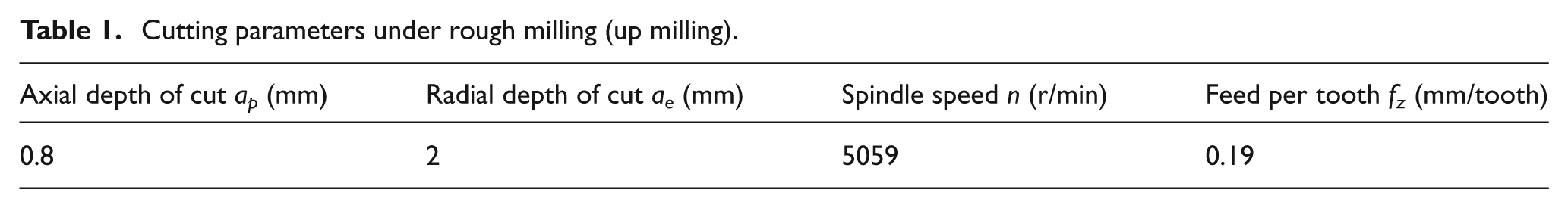
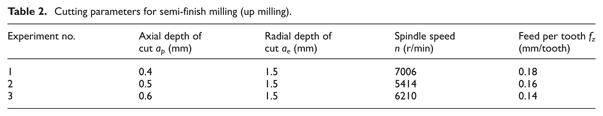
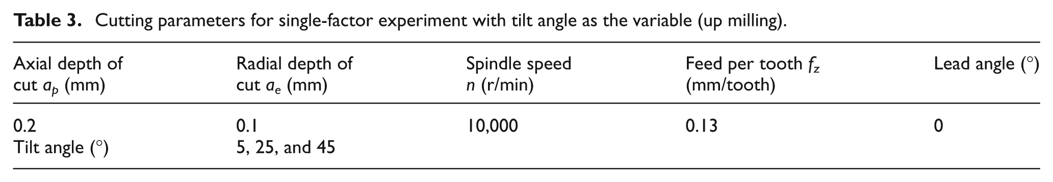
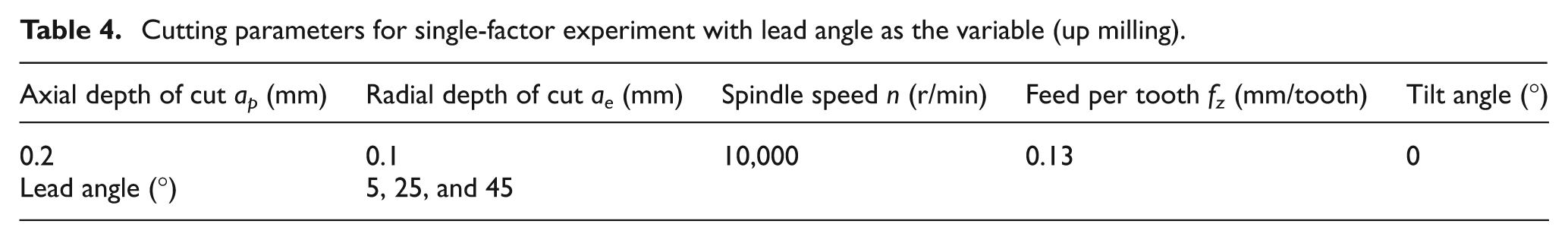
The cutting parameters for the milling experiments (rough milling, semi-finish milling, and finish milling with tool inclination angles) are shown in Tables 1–4. Three groups of cutting parameters are used as the semi-finish milling operation.
Cutting parameters under rough milling (up milling).
Cutting parameters for semi-finish milling (up milling).
Cutting parameters for single-factor experiment with tilt angle as the variable (up milling).
Cutting parameters for single-factor experiment with lead angle as the variable (up milling).
The definition of tool inclination angles employed in multi-axis ball milling process is shown in Figure 1. The tilt angle is evaluated by rotating the tool axis around feed direction, which passes through the ball center of the spherical part in the cutter, and the positive and negative values for tilt angle are presented in Figure 1(a). The lead angle is introduced by rotating the tool axis about the cross-feed direction. As shown in Figure 1(b), the positive lead angle is defined as rotating the tool axis in counterclockwise direction seeing from the positive direction of y-axis (cross-feed), while the negative lead angle is the inverse intersection angle.
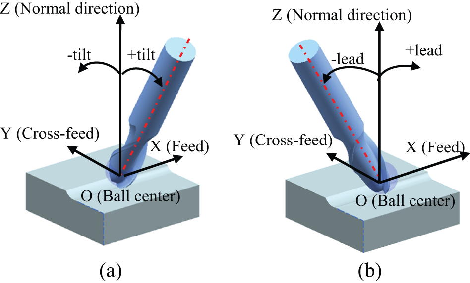
Definition of the tool inclination angles: (a) definition of tilt angle and (b) definition of lead angle.
Numerical simulation details
Computer-aided design (CAD) model of ball end mill was one of the most critical factors in the simulation. The geometrical model is shown in Figure 2. The cutting edges in the form of S shape are shown in the right part of Figure 2(a). The cutting edges of ball end mill could be divided into three parts on the basis of the position on the tool. The first one is cutting edges in the form of S shape, the second one is transition cutting edges connecting the spherical and cylindrical parts, and the last one is the cutting edges in cylindrical part of the cutter, as shown in the left part of Figure 2(a). The rake faces and flank faces of the spherical and cylindrical parts could also be observed. The chip pockets, curved surface of spiral grooves, and curved surfaces of withdrawal grooves with side cutting edges are presented in Figure 2(b).
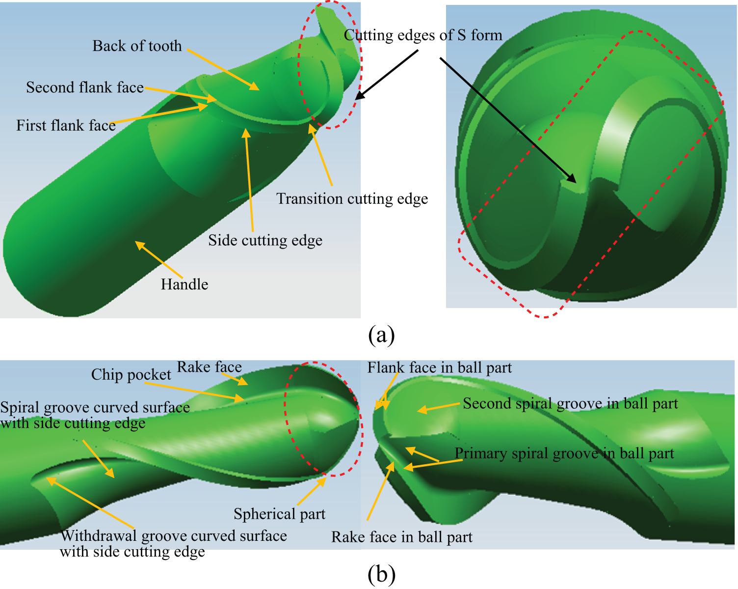
Geometrical models of the ball end mill: (a) cutting edges of cutter and flank faces of cylindrical part and (b) curved surface features included in the cutter.
Because only cutting edges in the spherical part of ball end mill engage with the workpiece in the practical machining parameters under finishing milling conditions with tool inclination angles in this work, the spherical part of the cutter is just selected as the cutting tool in the numerical modeling settings, which could greatly increase the simulation efficiency under the premise of accuracy guarantee. The FE simulations of various process parameters involving tool inclination angles were conducted in DEFORM 3D, and the settings for tool and workpiece under tilt of 45° and lead of 45° are shown in Figure 3. The spherical part was modeled as the cutting tool instead of the whole cutter, and a small cylinder was added on the spherical part in order to position the cutting part in the simulation environment. The workpiece was meshed using local re-mesh technology. The thermal boundaries of the cutter and workpiece were also considered in the simulation. The initial temperature of the environment, cutter, and workpiece is 20 °C, and the outside surface of the cutter and workpiece engages in the thermal exchange with the environment. The Johnson Cook material equation (1) was used to model the material behavior under high strain, stress, and high temperature
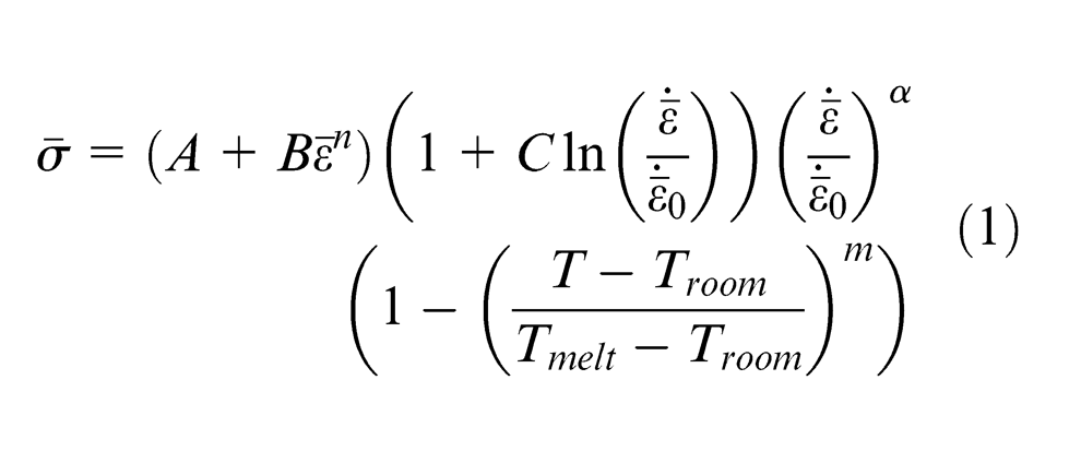
where
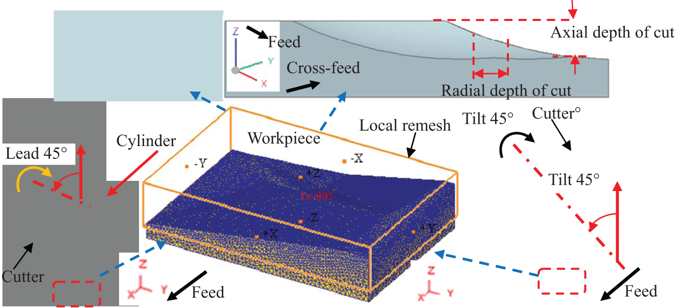
Diagram for the cutter and workpiece configurations with inclination angle (tilt of 45° and lead of 45°).
The cutter rotates around the tool axis together with the feed movement along the x direction, and hence, the actual motion is a combined motion of rotation and feed movement possessed by the cutter and workpiece, respectively. The rotation and feed parameters used in the simulation are in accordance with the practical milling experiments. The settings with regard to the relative position of tool–workpiece are presented in Figure 3. The relative position between the cutter and workpiece is important enough to influence the simulation results, and so the cutter inclination angle, the width of cut, and depth of cut should adjust accurately according to the actual cutting condition under each process parameters in order to realize high precision of the simulation. Feed direction is in accordance with x-axis, as shown in Figure 3, and cross-feed direction is identical with y-axis.
Chip geometry modeling and tool–work contact zone analysis
The chip geometry of ball end milling operation without considering the material deformation, which is modeled by CAD technology, is shown in Figure 4. The uncut chip geometry model was obtained by commercial software UG under up milling condition, and the detailed process parameters are ap = 1 mm, ae = 1 mm, fz = 0.3 mm/z, and n = 10000 r/min. Feed direction of the cutter is identical with the positive direction of x-axis, and the cross-feed direction is in accordance with the positive direction of y-axis, as shown in Figure 4. First, the in-process workpiece produced by the whole previous tool path and the partial current tool path could be generated by the Boolean subtraction operation of 3D geometry. In the first tool path, the cutter, with specific depth of cut, moves along the feed direction to run through the workpiece, and the intersecting part between the cutter and workpiece is a portion of a cylinder with the radius equal to the ball end mill radius. Then, the cutter moves a distance value of specific width of cut along the cross-feed direction, and the cutter moves some distance, penetration depth less than the workpiece length, toward feed direction. Next, the intersection between the cutter sweeping geometry and workpiece is removed from the workpiece geometry by Booleans minus method. Thus, the in-process workpiece including the transition surface of workpiece corresponding to the current cutting edge at specific cutting position is produced. Furthermore, the cutter moves a distance of feed per tooth toward the feed direction to approximately obtain the cutting position of the adjacent cutting edge, and the intersection geometry between the cutting tools and the in-process workpiece geometry after the previous Booleans minus calculation could approximately reflect geometric shape of the uncut chip, as shown in Figure 4. It is obviously seen that the chip is a sheet consisted of four surfaces and six lines. Surface 1 is the uncut surface in the top surface of blank, and surface 2 is the free surface generated by the previous cutting edge in the current cutting tool path. The small surface 3 that is generated by the adjacent cutting edges is removed from the surface generated by the previous cutting tool path without moving the cutter along the cross-feed direction, and surface 4 is the chip back surface induced by the current cutting edge. The chip tip point is the intersection point between the free surface and the surface generated by the previous tool path.
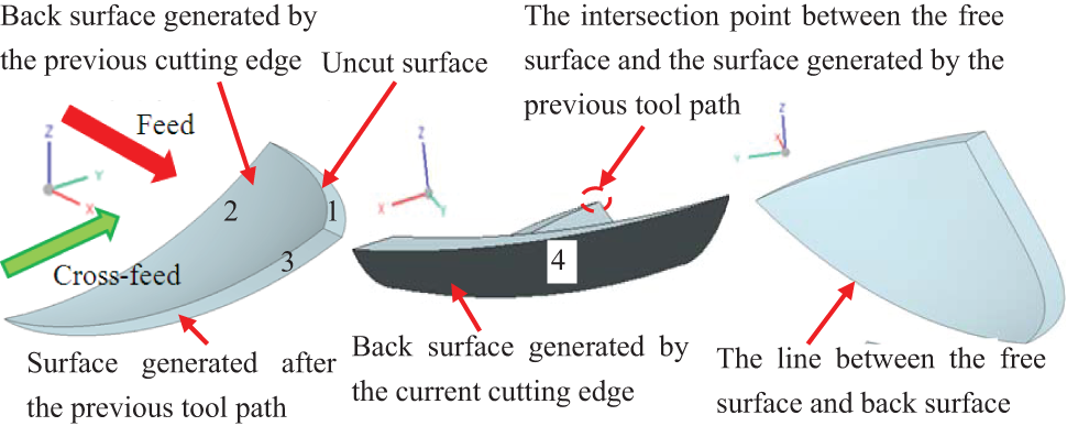
Theoretical uncut chip geometry generated in ball end milling (up milling).
The tool–work contact zone and the undeformed chip under special cutting conditions are shown in Figures 5 and 6. The tool tip engages in the cutting process when no inclination angles are employed in the machining operation, as shown in Figure 5(c), which shows the projection of the spherical part and the chip along the tool axis. The tool and workpiece settings under the condition without inclination angles are shown in Figure 5(a), and the corresponding enlarged view in the proper perspective is shown in Figure 5(b). In Figure 6, it can be seen that the entry and exit positions of the cutting edge engaging in the chip during chip formation process under different inclination angles are obviously different, which would directly influence the chip formation process and chip features. The chip projections in the spherical part of the cutter under different inclination angles are also different, which is due to the fact that the different inclination angles result in different cutting edge positions engaging with the workpiece in the chip formation process. Surface 4 is the potential contact zone between the cutter and the transitional surface in the workpiece, as shown in Figures 5 and 6.
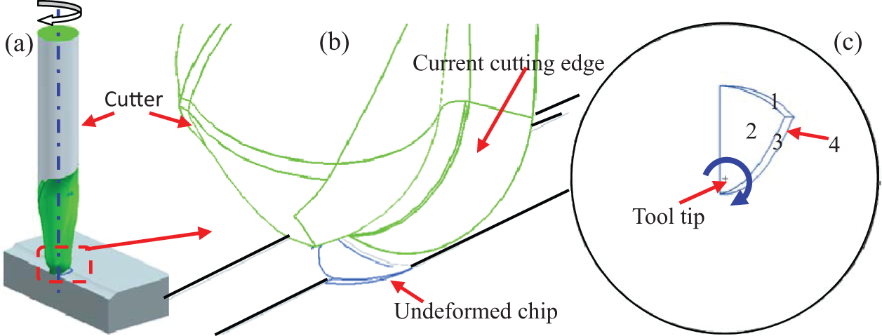
Tool–work contact zone and undeformed chip for three-axis ball end milling (up milling).
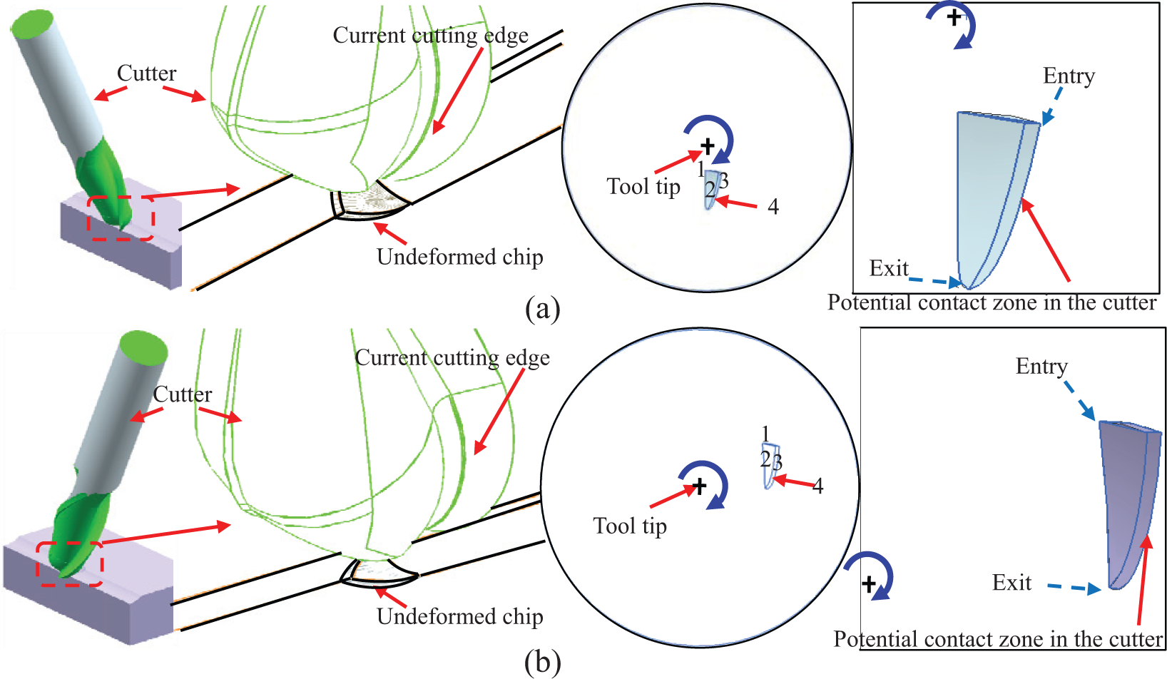
Tool–work contact zone and undeformed chip for special inclination angles under finish milling condition (up milling): (a) inclination angle of tilt of 25° and lead of 0° and (b) inclination angle of tilt of 0° and lead of 25°.
Results and discussions
FE modeling of the chip formation process
Analysis of the tool–work contact line under different inclination angles
The geometrical and kinematic descriptions of the chip formation process under finish milling conditions are presented in Figures 7 and 8, and the DEFORM 3D was employed in the geometry and kinematic settings of the cutter and workpiece. The numerical simulation of the tool–workpiece contact line considered the geometry and relative movement in accordance with the practical machining condition. The contact conditions between the tool and workpiece corresponding to various tilt and lead angles during the chip formation process are shown in Figures 7 and 8. The position of the contact lines in the chip root induced by tilt and lead angles is obviously different during the chip formation process. It could be seen that the two cutting flutes engage in the cutting process because the tool tip is directly in contact with the uncut materials under tilt of 5°, and so the contact lines are consisted of two parts. The contact lines gradually become long at the initial cutting stage and then become short at the later stage under the special tilt and lead angles.
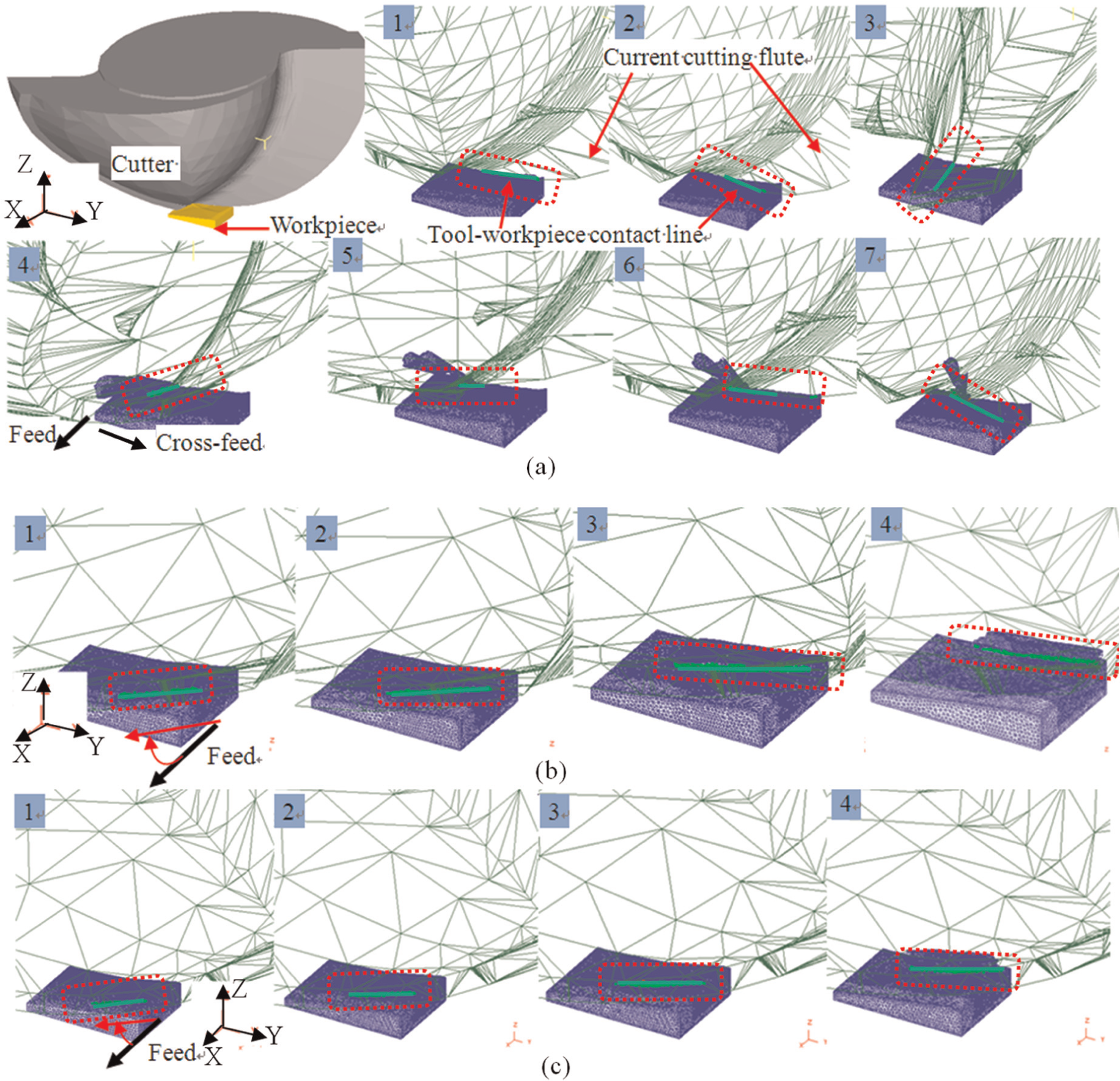
Tool–workpiece contact line varying processes under various tilt angles: (a) chip formation process under tilt of 5°, (b) chip formation process under tilt of 25°, and (c) chip formation process under tilt of 45°.
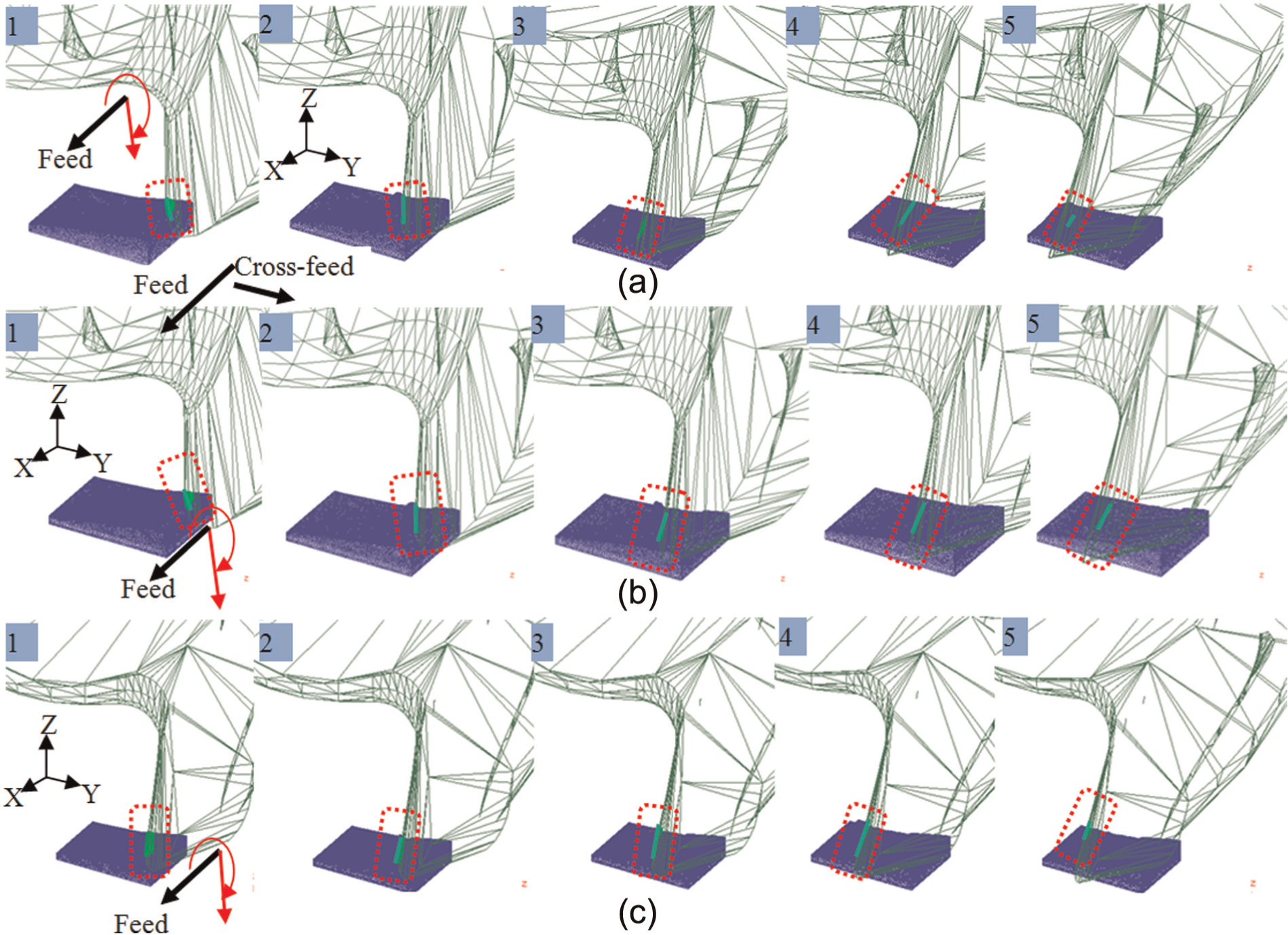
Tool–workpiece contact line varying processes under various lead angles: (a) chip formation process under lead of 5°, (b) chip formation process under lead of 25°, and (c) chip formation process under lead of 45°.
The intersection angles between the contact line and the feed direction are acute angle under tilt of 25° and 45°, and the in-process chip thickness gradually decreases with the cutting flute revolution after short increment at the initial cutting process. While the corresponding intersection angles under lead of 5°, 25°, and 45° are obtuse angles, the in-process chip thickness first increases and then decreases at the final cutting stage.
It can also be found that different parts of the cutting edges engage in the cutting process under different tool inclination angles, and furthermore, the corresponding cutting speeds, which would directly influence the cutting temperature, are different. Hence, the extent of thermal loads influence on the chip is different, and the difference will be reflected in the chip color and morphologies.
Verification of the cutting forces between the simulation results and experimental data
The cutting forces obtained from simulation corresponding to tilt of 25° are shown in Figure 9(a). The variations of cutting forces in each direction present the load between tool and workpiece in the entry and exit processes of single tooth. First, the cutting forces all increase with the increment of simulation step or machining time and then decrease after the cutting forces reach a maximum in each direction. The variations of cutting forces are closely related with the chip formation process, and material quantities separated from the workpiece gradually increase at the initial stage. The material quantities separated from the basal body increase with the chip formation process going on, and moreover, the heat generated from plastic deformation and friction between the tool and workpiece is faint. As a result, the forces acted on the workpiece are small at the initial moment and then gradually increase. With the material separation from the workpiece going on, heat derived from deformation and friction increases much, and temperature rise in chip and active region of tool–workpiece is great. Next, the materials are softened, and the material quantities separated from the workpiece gradually decrease in the process of single tooth cutting out. Hence, the forces acted on the workpiece are small at the last stage of chip formation. The compound influence of heat generated in the cutting process and space geometric features during the chip formation process leads to the variation trends of the cutting forces, which is in accordance with the actual milling process and may serve as an indirect proof of effectiveness of the simulation model.
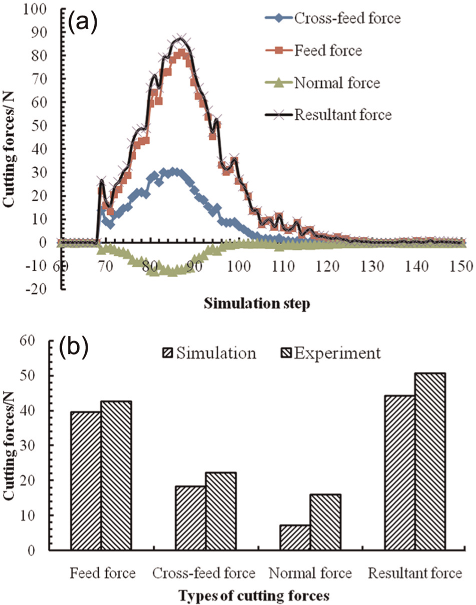
Cutting forces verification between simulation and experiment under tilt of 25°: (a) variations of the cutting forces for tilt of 25° and (b) comparison of average and resultant cutting forces between simulated and experimental result.
The average cutting forces of each direction are extracted from the simulation results to compare with the experimental data, which is shown in Figure 9(b). The height of bar represents the value of cutting force in the corresponding direction. The percentage errors are 7.45% and 17.52% for the average cutting forces in x direction (feed) and y direction (cross-feed), respectively. The machining vibration would apparently influence the cutting force in normal direction, and small vibration gives rise to large cutting force variation in normal direction. The larger percentage error of cutting force in z direction is mainly due to the tool vibration in practical machining. The cutting forces with small values are all measured under finishing machining condition. The experimental values are treated as the denominator in the calculation of the percentage, and so a small amount of deviation between the simulation data and the experimental values will lead to a large percentage error. The percentage error for the resultant cutting force obtained by solving the square root of sum of squares with regard to each average cutting force is 12.95%, which is acceptable.
Chip temperature field and variations of the maximum chip temperature
Figure 10(a) and (b) shows the simulated chip formation process, especially the chip temperature field in 3D view, under tilt of 25° and lead of 25°, respectively. The toolbar with different colors on the right side of the chip temperature field shows the temperature value corresponding to the specific color. It could be obviously seen that the entry and exit positions and posture of the engaged cutting edges under the different tool tilt and lead angles are different from each other, which is also demonstrated by the diagram presented in Figure 6. Chip curl phenomenon could also be observed, which is mainly due to thermal softening effect of the chip and the movement characteristics of the engaged cutting edges bringing about the chip outflow along tool rake face.
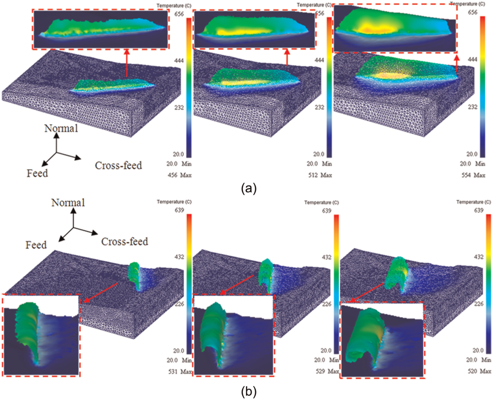
Diagram of the chip temperature during cutting process under tilt of 25° and lead of 25°: (a) chip temperature field under tilt of 25° and (b) chip temperature field under lead of 25°.
Figure 11 shows the variations of maximum chip temperature with tilt angle and lead angle. In the cut-in and cut-out process of only one tooth, the maximum chip temperature first increases with the cutting process going on and then decreases until a certain stable value. The chip maximum temperature increases greatly at the initial cutting stage, and the increasing trend gradually slows at the following cutting stage. Then the temperature slowly reduces in the later stage before the current flute finishing the cutting behavior. The increment of chip temperature is mainly due to the severe plastic deformation and friction between the engaged cutting edges and the work materials at the initial cutting stage, and the chip temperature gradually reduces along with the ease of the plastic deformation and heat transferring into the cutter and surrounding environment.
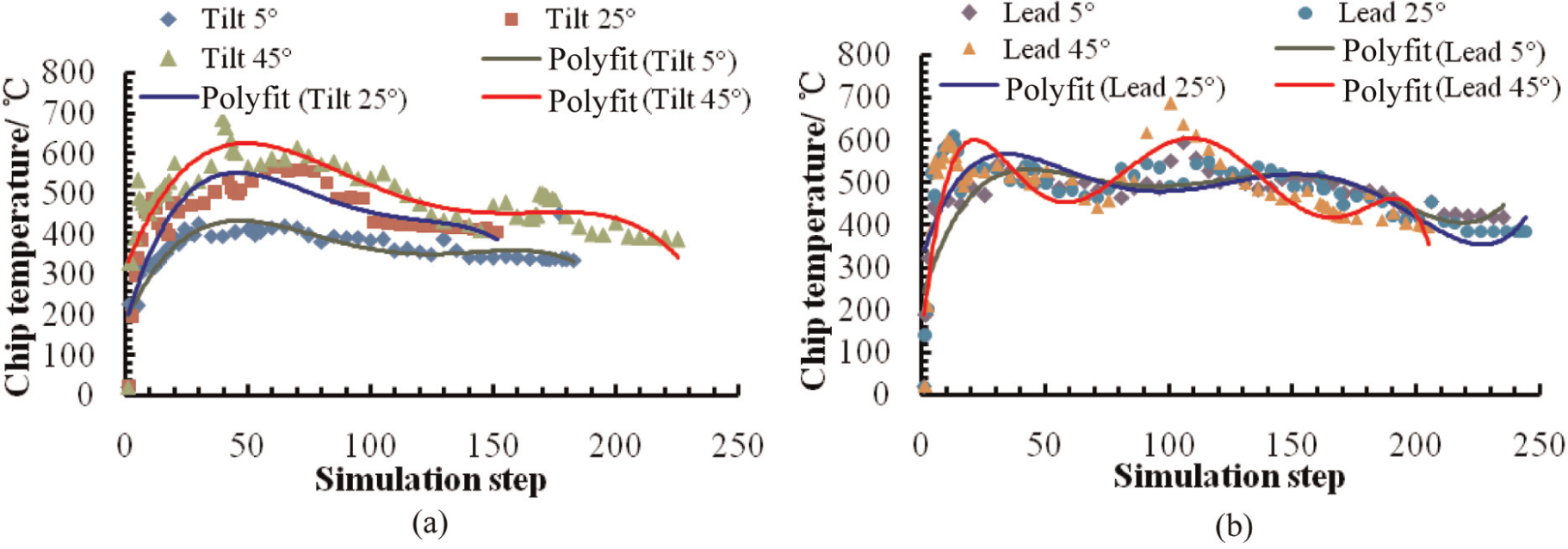
Variation of maximum chip temperature versus different inclination angles: (a) variations of chip temperature with lead angle and (b) variations of chip temperature with tilt angle.
On the whole, the chip temperature increases with the increment of tilt angle, as shown in Figure 11(a). This is mainly due to the effective cutting speed of the engaged cutting edges increases with the increment of tilt angle, which would directly lead to the increment of chip temperature. The final maximum chip temperatures when the current engaged cutting flute completes the cutting action with regard to various tilt angles are approximately 400 °C. The overall varying trend of maximum chip temperatures corresponding to different lead angles does not show significant difference, but the maximum chip temperatures of lead of 25° and 45° are larger than the one of lead of 5° at the initial cutting stage when lead angles are adopted.
Chip morphologies and color
The chips under optical microscope are shown in Figure 12. The color corresponding to the chips generated under different cutting parameters is obviously different to each other. Large material removal rate is adopted under roughing and semi-finishing conditions, and the deformation and friction intensity are far more than the corresponding intensity under finish milling condition. Consequently, plenty of heat generated by the material removal behaviors brings about large temperature rise, which would obviously influence on the chip. The chip color under rough milling condition is obviously dark red. The chip color of semi-finish milling process gradually becomes dark from semi-finish 1 to semi-finish 3, as shown in Figure 12(a), which is mainly caused by the increment of depth of cut for these three groups of cutting parameters leading to more cutting heat generated in the chip formation process.
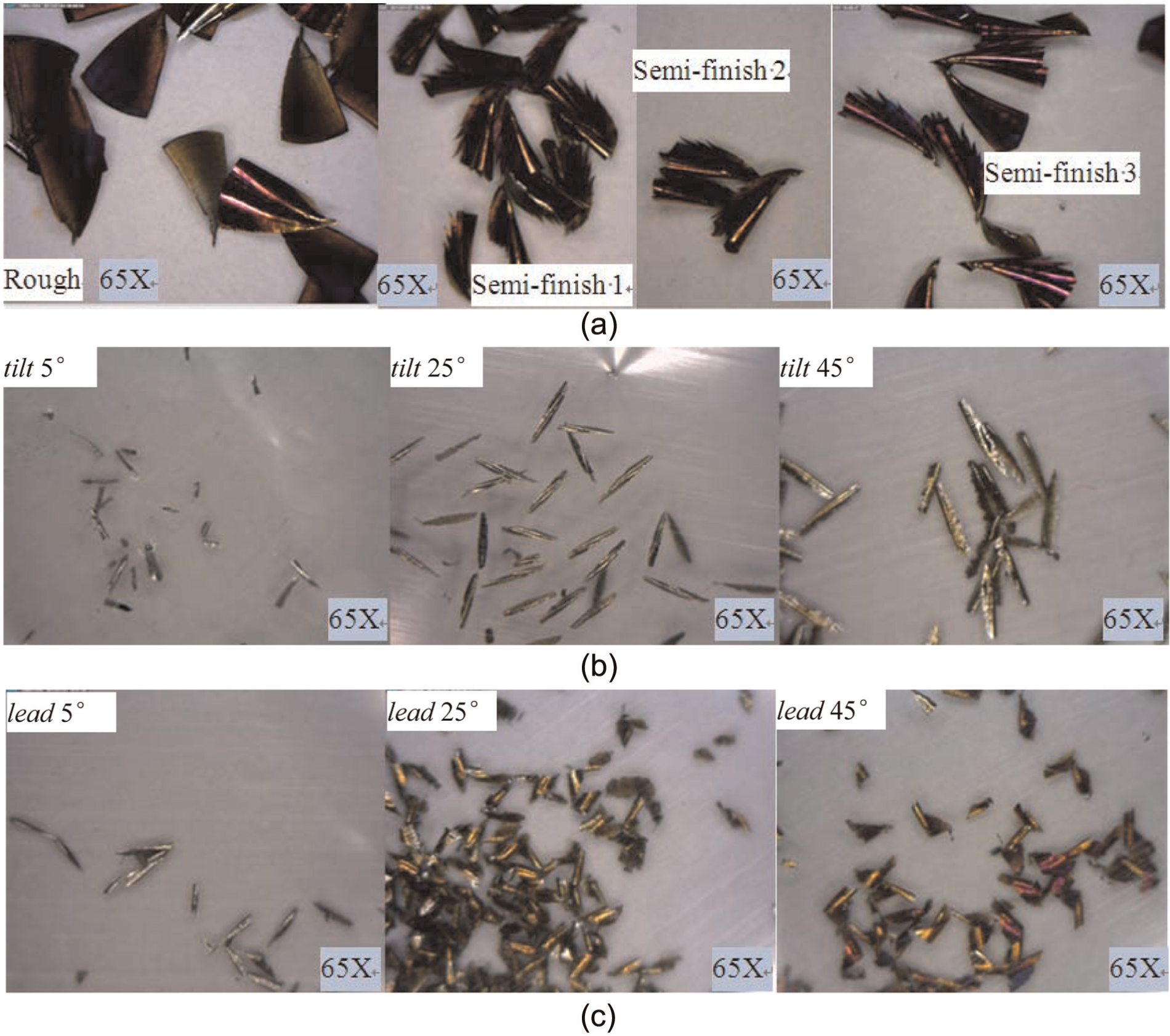
Chip morphologies under various cutting conditions with optimal microscope: (a) chips under rough and three groups of semi-finish milling conditions, (b) chips under finish milling condition with various tilt angles, and (c) chips under finish milling condition with various lead angles.
In general, the chip temperature plays an important role in the chip color variations. The maximum chip temperature increases with the increment of tilt angle, and the detailed information is presented in Figure 11(a). Variation of the maximum chip temperature with the increasing lead angle is not obvious, but at the initial stage of the chip formation, the corresponding maximum chip temperature at lead angles of 25° and 45° is larger than the maximum chip temperature at lead angle of 5°. In the middle stage of the chip formation process, larger maximum chip temperatures, as shown in Figure 11(b), appear under lead angle of 45°, which is directly related to the high efficient cutting speed of the engaged cutting edges corresponding to this tool inclination angle. The variation conditions of chip temperature directly determine the oxidation degree of elements in chip material, which include element Fe and various alloy elements, which eventually results in macro color changes in chip. The chip color gradually becomes dark with the increment of tilt angle and lead angle, and the scrap chips are easier to appear under small tool inclination angles, as shown in Figure 12(b) and (c).
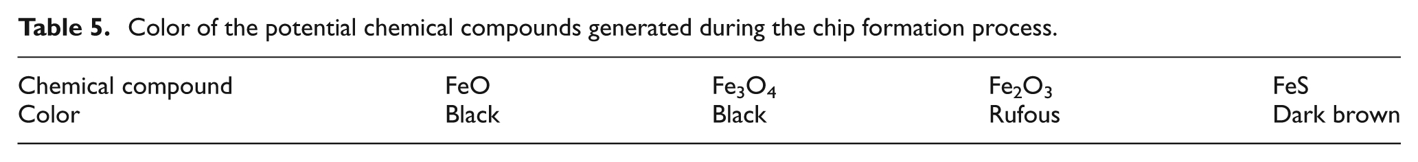
More cutting heats are induced in the rough and semi-finish milling condition. Most of the cutting heat generated in milling process transferred into the chip, and the chip materials equivalently experience a specific type of heat treatment, air cooling after heated to a certain temperature. Meanwhile, the chemical reaction between the existing reactive gas in the air and the metal materials under the condition of high temperature would happen, and iron oxides may probably be generated. 27 According to the EDS analysis of the chip materials, as shown in Figures 17 and 18, the distribution of elements could be detected. The potential chemical reactions are presented in equations (2)–(5), and the potential chemical compounds generated during chip formation process are shown in Table 5. The iron oxide with trivalent ferric ion presents red color, and so the chips present red color under rough and semi-finish milling conditions through optical macro-observation. Due to the different temperatures in the different positions in the chip, the degree of reaction is varying, which would directly affect the color and luster with regard to different positions of the chips. Chip material is likely to be changed under the condition of sufficient oxygen. Hence, the chip color is closely linked with oxidation compositions, such as different oxidation states of the iron and oxidation of the alloying elements, within the main body of chip. 27
Color of the potential chemical compounds generated during the chip formation process.
Analysis of chip under rough milling condition
The chip morphologies under rough milling condition were shown in Figure 13, and the free surface and back surface of the chip were presented, respectively. The back surface with glossy feature, which is generated by the following engaged cutting edge, is convex. The chip free surface is concave, and streaks with various directions appear. The rough free surface experienced two times of thermal and mechanical loads during the chip formation process, and special chip flow characteristics along the tool rake face determined the curved feature.
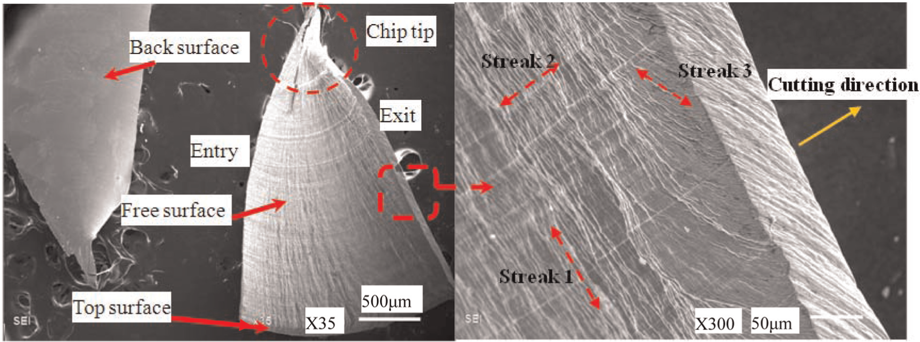
Chip morphology (ap = 0.8 mm, ae = 2 mm, n = 5059 r/min, fz = 0.19 mm/tooth, tilt = 0°, and lead = 0°).
The first kind of streak (streak 1) is perpendicular to the cutting direction, which is induced by the bending of the free surface and the mutual extrusion between the deformed chip material and the uncut material in the cutting zone during the cutting process. Streak 2 is parallel to the cutting direction of the engaged cutting edges in the spherical part of the ball end mill, and this kind of streak is generated by the scraping action of the previous engaged cutting edges. Streak 3 is caused by combined action of the two adjacent engaged cutting edges. The free surface was machined by the previous engaged cutting edge, and the back surface was generated by the following engaged cutting edge.
Cutting edge of the ball end mill could be considered as the combination of a series of infinitesimal microelement, and the cutting behavior of each micro cutting element in the engaged cutting edge could be approximately treated as an oblique cutting process.19,20,24,26 With regard to the oblique cutting process, the extrusion effects between the tool rake face and the back surface of the in-process chip are produced during the chip formation process, and meanwhile, the extrusion effects between the tool flank face and the free surface of the uncut chip in the following machining operation are also generated.
Considering the extrusion and kinematic characteristics of the chip formation, a certain friction would act on the interface between the chip and each infinitesimal cutting element, 28 and so summation of the effects of all the infinitesimal cutting elements within the whole engaged cutting edge gives rise to the friction effects on the chip during ball end milling process. The friction would also make some contribution to the generation of the thermal and mechanical loads in shear zone. 7
Furthermore, the friction effects directly affect the chip micromorphology. The friction between the tool flank face and the chip free surface would lead to the relative slide of the end zone in free surface to the chip back surface generated by the following engaged cutting edge, and furthermore, the friction between tool rake face and the chip back surface in the cutting process by the following engaged cutting edge directly makes the slide of the back surface. Also, the effects of thermal softening action 7 on the uncut chip materials promote the relative slide between the chip materials in different locations. Finally, the special streak presents a certain intersection angle with the cutting speed.
It also can be seen that the flocculent feature appears in the chip tip, and this phenomenon is induced by the cutting engagement of the tool tip. Because the cutting velocity of the tool tip is 0 in the cutting parameters without the tool inclination angles, the squeezing action during the tool revolution process directly leads to the damage of the chip end.
Analysis of chip under semi-finish milling condition
The chip morphologies under semi-finish cutting parameters are shown in Figure 14. The width of cut was fixed at 1.5 mm for the three groups of cutting parameters, as shown in Table 2. The streaks also exist like the ones generated in the chips under rough milling condition.
Chip morphologies under semi-finish milling condition: (a) experiment no. 1, (b) experiment no. 2, and (c) experiment no. 3.
The curly features are apparently presented in the cutting in part marked as “Entry” in Figure 14(a). The thermal stress cracks in the part of the flute cutting out of the workpiece are more easily to be seen, and even the sawed tooth chips significantly happen. The cutting flutes of the cutter in spherical part are spiral, and the engagement line between the cutting edge and the uncut materials is also spiral. Hence, the undeformed chip materials are separated away from the workpiece section by section, and so generation of the sawed tooth chips is enhanced. Moreover, under semi-finish milling parameters, the chip thickness that is within the middle level of the chip thickness formed in rough and finish milling conditions is approximate, and the coupling effects of thermal and mechanical loads essentially contribute to the generation of the saw tooth chips.
Heating could make the chip materials softening together with specific expansion, and then chip is cooled in the air after separating from the workpiece. And furthermore, a certain degree of shrinkage in chip materials is caused in the cooling process. Considering the cutting edges consisted of a series of infinitesimal elements, the cutting condition of each infinitesimal element is equivalent to the oblique cutting. The thermal and mechanical coupling effects with regard to the instantaneous shear zone formed during the chip formation process could also affect the final chip morphologies. In general, if the chip thickness is large enough, it is not easy to induce the material separation in the chip margin. If the chip thickness is relatively small, chip materials are easy to shed from the whole chip, as presented in Figures 15 and 16. For semi-finish milling, the chip geometry dimensions are just between the chips under rough and finish milling conditions. Under semi-finish milling condition, the coexistence of heating, cooling, thermal and mechanical coupling effects with regard to the instantaneous shear zone, and appropriate chip geometry dimensions act on the chip, and so the chips corresponding to semi-finish milling present serrated forms in the margin parts when experiencing air cooling after heated to a certain temperature, as shown in Figure 14.
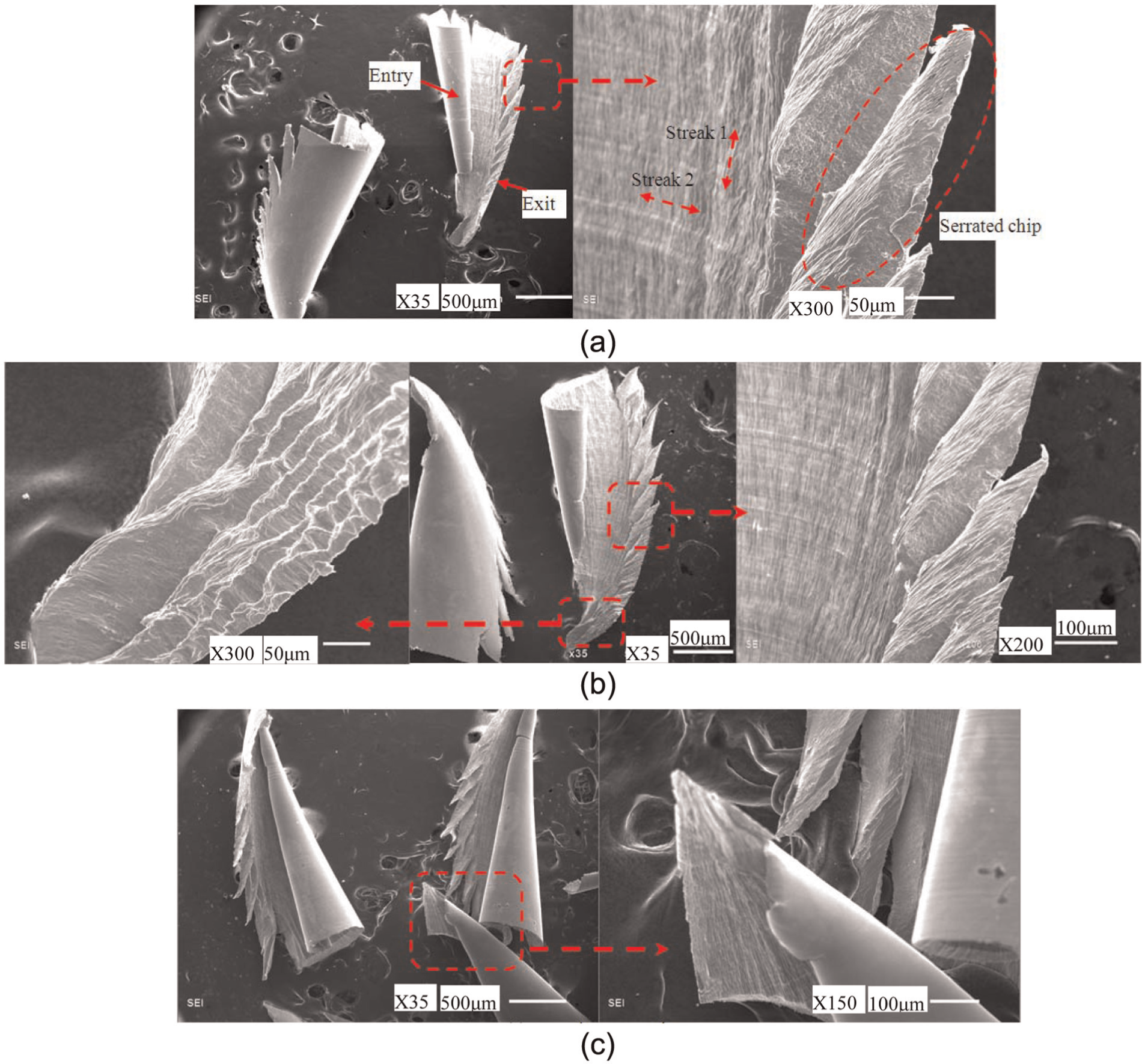
Chip morphologies (ap = 0.2 mm, ae = 0.1 mm, n = 10,000 r/min, fz = 0.13 mm/tooth, and lead = 0°): (a) tilt = 5°, (b) tilt = 25°, and (c) tilt = 45°.
Chip morphologies (ap = 0.2 mm, ae = 0.1 mm, n = 10,000 r/min, fz = 0.13 mm/tooth, and tilt = 0°): (a) lead = 5°, (b) lead = 25°, and (c) lead = 45°.
Analysis of chip corresponding to finish milling condition
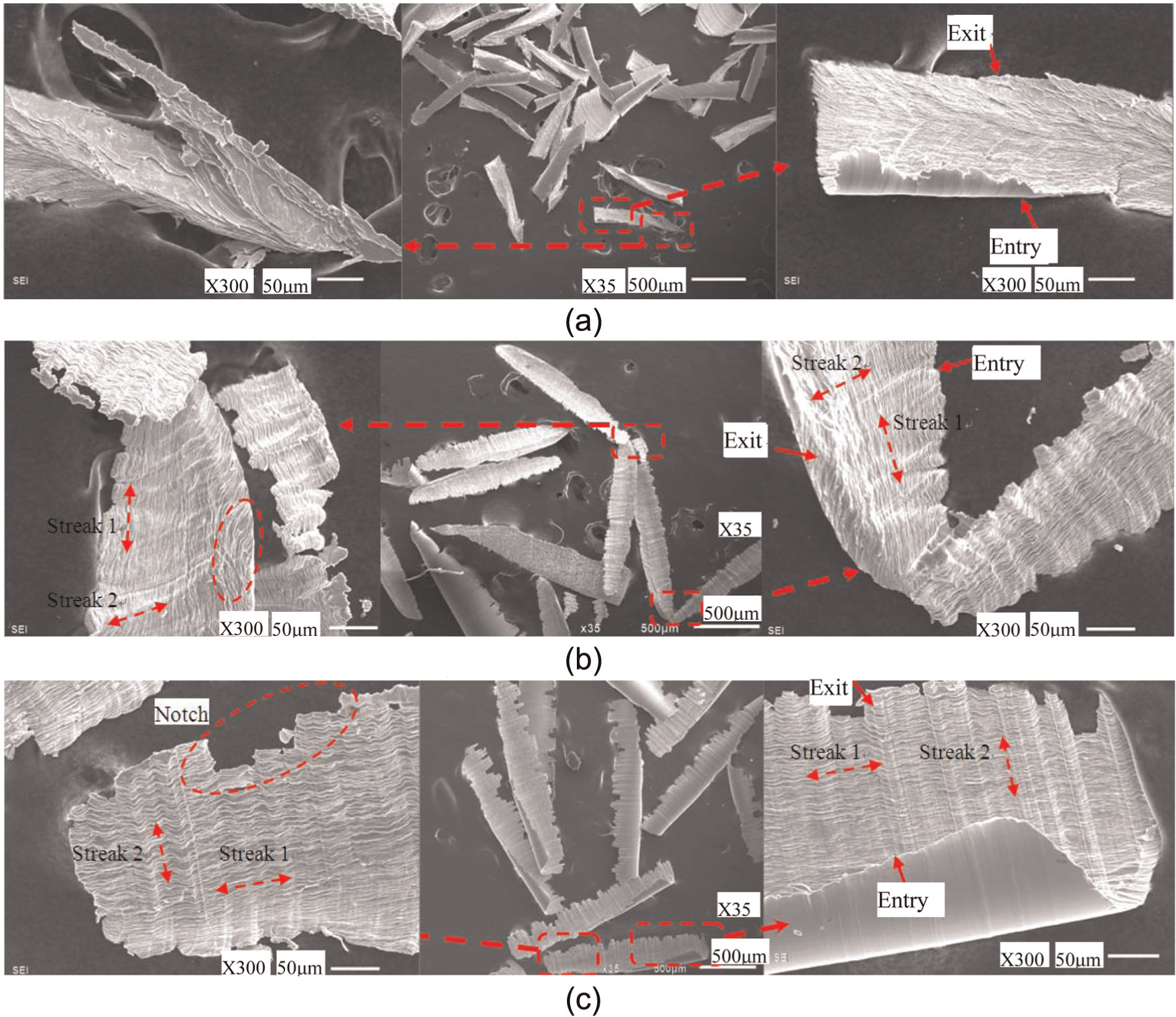
The chip morphologies under finish milling conditions with various tool inclination angles are shown in Figures 15 and 16. The tool tip engages in the removing process of chip materials when tilt angle is 5°, and so the extrusion action of the tool tip on the end part of the chip is obvious. Furthermore, the textures of the chip end are not regular. Furthermore, the burrs easily appear, as shown in Figure 15(a), and the machined surface quality may probably deteriorate under this cutting condition.
The nicks could be easily seen under tilt of 25°, and this feature appears more frequently when tilt angle is 45°. This is mainly due to the high chip temperature generated under the special cutting parameters of tilt of 25° and 45°. At the same time, more nicks appear in the position of chip at the cutting-out location of the current cutting edge than the one at the other side of the chip marked with “Entry.” The chip thickness is relatively large at the cutting in location, which is marked with “Entry,” and so the partial materials are difficult to break away from the main chip body. However, the chip thickness at the location “Exit” is small, and responses to the mechanical and thermal loads in this location, which is presented in terms of the pieces of chip materials breaking away from the chip main body, are more intense.
The chip thickness and chip volume under finish milling parameters are smaller than the ones with regard to rough and semi-finish milling conditions, and so the relative sliding behavior perpendicular to the cutting speed and the machining marks of the engaged cutting edge are more apparent. As a result, the streaks along with and perpendicular to the cutting direction could obviously be seen, as shown in Figure 15, especially Figure 15(b) and (c). The chip tip may probably separate from the chip main body owning to the extrusion effect of the engaged tool tip, and so the relative round geometry appears at the chip tip location, as shown in Figure 15(c).
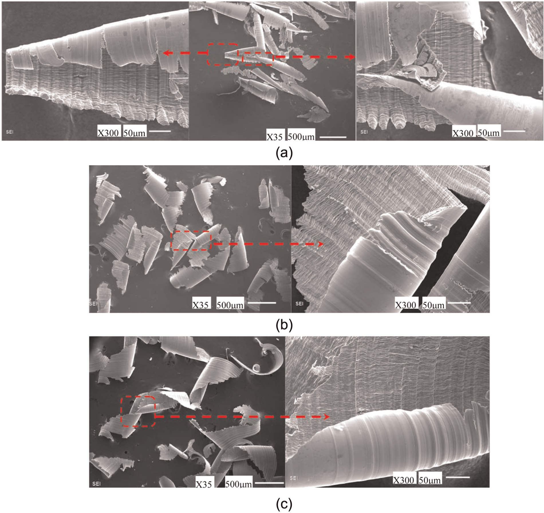
As shown in Figure 16, the chip morphologies under various lead angles are presented. The EDS analysis of special points on the chip corresponding to lead of 25° and 45° is shown in Figures 17 and 18, respectively. Curly phenomena in the chips under various lead angles are obviously presented in Figure 16. The tool tip is far away from the tool–workpiece interaction region against the feed direction under positive lead angle, and so the engaged cutting edges would have high effective cutting radius and cutting speed. Consequently, the high cutting temperature approximately 500 °C shown in Figure 11 giving rise to the material softening effects is induced, and the obvious curly features happen together with the mechanical loads acting on the chip and the chip flow characteristics along the tool rake face. Also, under the cutting condition with tool lead angle, the cracks along the cutting speed direction of the engaged cutting edge are more likely to appear comparing with the condition with tilt angle. The orientation and position of the engaged cutting edges cutting in the uncut materials, as shown in Figures 7 and 8, directly influence the chip geometry under various inclination angles, as shown in Figures 15 and 16.
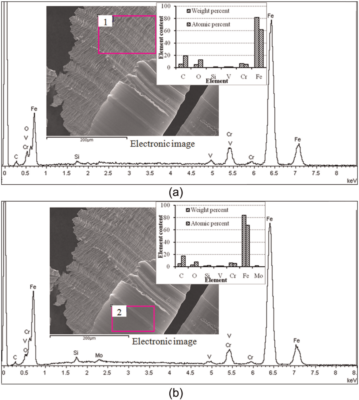
EDS analysis of the chip under lead of 25° (ap = 0.2 mm, ae = 0.1 mm, n = 10,000 r/min, fz = 0.13 mm/tooth, tilt = 0°, and lead = 25°): (a) EDS analysis of the chip free surface and (b) EDS analysis of the back surface.
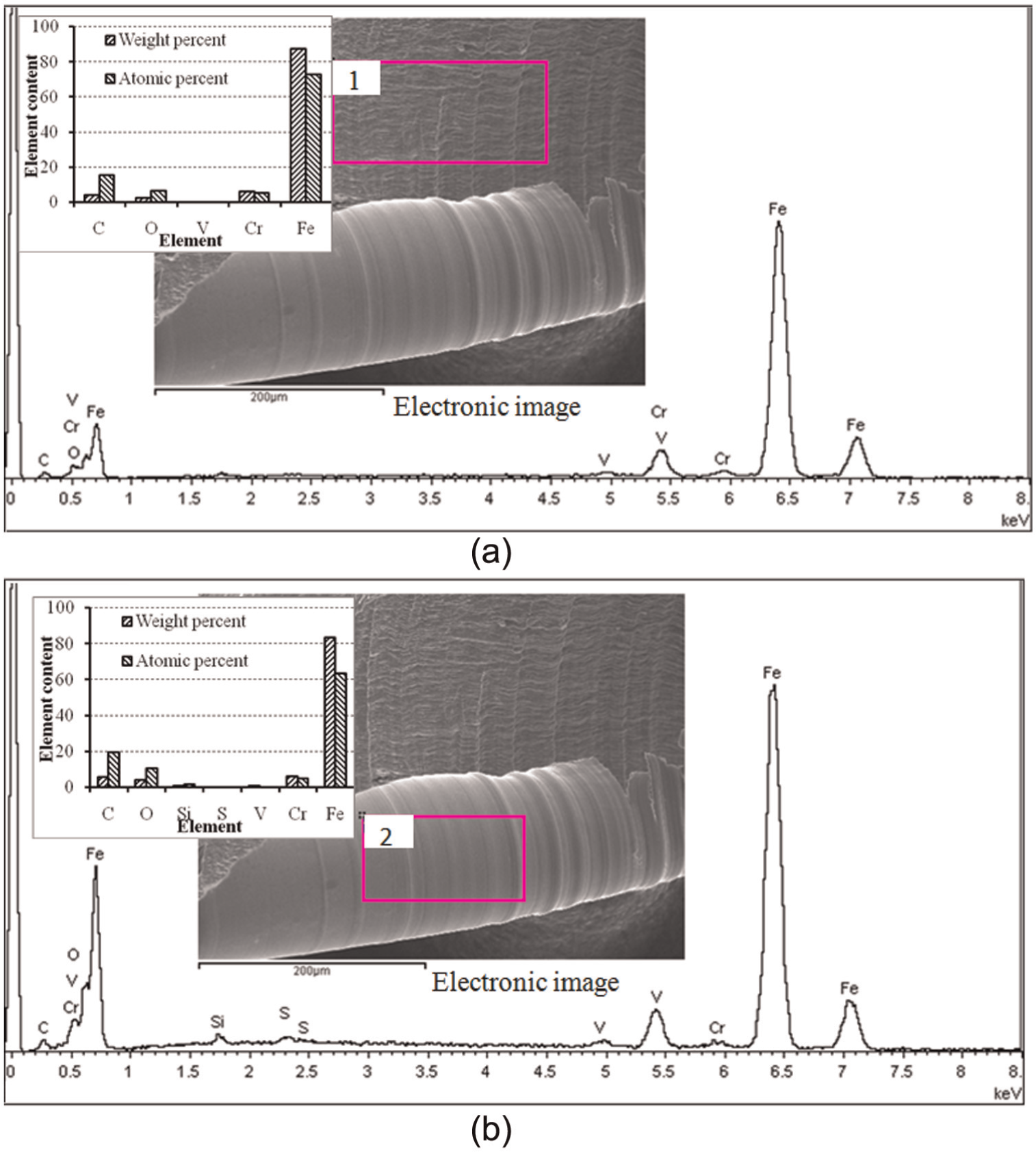
EDS analysis of the chip under lead of 45° (ap = 0.2 mm, ae = 0.1 mm, n = 10,000 r/min, fz = 0.13 mm/tooth, tilt = 0°, and lead = 45°): (a) EDS analysis of the chip free surface and (b) EDS analysis of the back surface.
The detailed contents of various elements on the selected zone on the free surface and back surface of chip generated under lead of 25° are also presented in Figure 17(a) and (b). The contents of element O, which is evaluated by weight percent and atomic percent, at the free surface zone 1 are a little large than the ones at the back surface zone 2, as shown in Figure 17, which could indirectly demonstrate that the reaction degree between the chip free surface and active gas in air more intense than the chip back surface under the effect of cutting heat under lead of 25°. The primary chemical oxidation reaction between Fe and O is presented in equations (2)–(4) 27


Special zone 1 shown in Figure 17(a) is directly in contact with air, and this position, which finally separates from the workpiece under lead of 25°, indirectly heated by the heat generated during the later cutting stage. Special zone 2 in Figure 17(b) that is directly in contact with the rake face of the current engaged cutting flute first separates from the workpiece under lead of 25°, which means the thermal load acts on this zone at the initial cutting stage, and the chip curl would lead to the back surface with high temperature in contact with air. Hence, favorable external condition for the chemical reaction between the chip and surrounding active materials could be achieved.
The detailed contents of various elements on the selected zone on the free surface and back surface of chip generated under lead of 45° are included in Figure 18(a) and (b). It can be seen that the element O exists in the free surface and back surface of the chip, and this phenomenon could demonstrate that the chemical reaction happens between the chip and surrounding air both in the free surface and in the back surface. Furthermore, more active gases, such as O and S, participate into the reaction behavior in the chip formation process on the back surface, as shown in Figure 18(b) than the free surface presented in Figure 18(a) under the special cutting parameters with lead of 45°. The potential chemical between the elements Fe and S is represented as follows

FeO and Fe3O4 own the color of black, while the color of Fe2O3 is rufous. Ferrous sulfide FeS is six-party crystals with color of dark brown. Hence, the chip color is closely related to oxidation compositions within the main body of chip. More and more FeO and Fe3O4 directly result in the chip color being darker and darker. The chip colors were not entirely due to different oxidation states of the iron, and the oxidation of the alloying elements also makes some contribution to the variation in chip colors. 27 The EDS analysis of chip materials could provide support for the possibility of chemical reaction and chip color variation previously discussed in the text.
Conclusion
Ball end milling of H13 die steel under rough, semi-finish, and finish milling conditions was carried out, and the tool inclination angles were considered in the finish milling process. The chip geometry and tool–work contact conditions, chip formation process, chip morphologies, and chip color under various process parameters were discussed. The position of entry and exit of the cutting edge and the projection of tool–work contact zone along tool axis are different from each other under different tool inclination angles in the chip formation process.
The red color of chips under rough and semi-finish milling parameters could obviously be seen, which is mainly due to more cutting heat induced in cutting process bringing about more oxides presenting red color through macro-observation, such as ferric oxide. Chip material is likely to be changed under the condition of sufficient oxygen. Considering the cutting edges consisted of a series of infinitesimal elements, the cutting condition of each infinitesimal element is equivalent to the oblique cutting. The thermal and mechanical coupling effects with regard to the instantaneous shear zone formed during the chip formation process could also affect the final chip morphologies. In general, if the chip thickness is large enough, it is not easy to induce the material separation in the chip margin. If the chip thickness is relatively small, chip materials are easy to shed from the whole chip. For semi-finish milling, the chip geometry dimensions are just between the chips under rough and finish milling conditions. Under semi-finish milling condition, thermal and mechanical coupling effects with regard to the instantaneous shear zone including heating, cooling, extrusion, and friction also act on the chip. Consequently, the chips under semi-finish milling condition present the patterns of saw tooth under specific conditions.
The orientation and cutting positions at the initial cutting stage with regard to the current engaged cutting edges are different from each other under various tool inclination angles. Scrap chips easily appear under the cutting condition with small inclination angles, either tilt angle or lead angle. Moreover, the extrusion effects of tool tip on the chip cusp are obvious when small tilt angle, such as tilt of 5°, is used. Inclination angles of 25° and 45° could be adopted for both tilt and lead angles considering the avoidance of tool tip engaging in cutting, while tilt of 25° is not a reasonable selection when the axial depth of cut is large. Under up milling condition using larger depth of cut, the tool tip corresponding to tilt of 25° probably engages with the transition surface generated during the multi-axis ball end milling. The extrusion action between the tool tip with cutting speed of zero and the workpiece is intense, and the cutting conditions would directly be deteriorated. The extrusion effect of tool tip on the uncut workpiece material could be observed in Figure 13, and the incompact and fibriform organizations appear in the chip tip.
The streaks parallel and perpendicular to the cutting direction of the engaged cutting edge exist in the free surface of chips under finish milling conditions with tool inclination angles, which is due to the machining marks derived from the infinitesimal engaged cutting edges and the mutual extrusion and slip between the chip internal materials. The curly features in chips could be obviously noticed under lead angles, and cracks along the cutting trajectory of the engaged cutting edges appear frequently. The thermal effects on the chip materials are prominent. Both the free surface and back surface on the chips are affected by the chemical reaction with surrounding active substances, such as oxygen, and the active elements are detected in special zone on the chip surfaces.
Footnotes
Declaration of conflicting interests
The authors declare that there is no conflict of interest.
Funding
This study was supported by the National Basic Research Program of China (2009CB724402).