
Abstract
This study investigated the effect of boron-doped and undoped diamond coatings on the cutting performance of cobalt cemented tungsten carbide (WC-Co) drills when drilling CFRP. Three types of diamond coating, as boron-doped microcrystalline (B-MCD), boron-doped nanocrystalline (B-NCD), and undoped nanocrystalline (NCD), were deposited on specially designed for drilling of CFRP one-shot drills by the hot filament chemical vapor deposition (HFCVD) method. The coating characteristics, such as surface morphology, roughness, carbon structure, and interfacial adhesion, were investigated. Then cutting tests were carried out, and the tool’s flank wear, thrust force, and torque were evaluated. For comparison of cutting performance, non-coated WC-Co drills were used in the tests as well. Furthermore, drilled holes were inspected in terms of peel-up and push-out delamination. According to the results, the B-MCD coated drill presented advantages in tool life, and quality of drilled holes over the NCD and B-NCD coated drills. Also, the results confirmed the adhesion enhanced effect of diamond coating to WC-Co substrate through boron doping of the layer.
Introduction
It is well known that carbon fiber reinforced plastics (CFRP) are used for the aerospace industry due to their superior mechanical properties, especially strength to weight ratio, that gives benefit in weight control compared with other applied materials. 1 However, CFRP is one of the difficult-to-cut materials due to the abrasive effect of carbon fibers in the plastic matrix, which leads to severe tool wear, and consequently, its short life. Furthermore, machined surfaces have inherent defects of the composite material, such as delamination, burrs, etc. Based on research data overviews, three key factors, such as tool shape, material, and cutting parameters, influence the tool life and CFRP defects.2–8 Moreover, combinations of specially designed WC-Co based cutting tools with polycrystalline diamond coatings are one of the best ways to increase the tool life and to reduce the CFRP product defects.9,10 For instance, Xu et al. 9 studied the cutting performance of two diamond-coated WC-Co drills, namely, conventional twist drill and one-shot drill with equal diameters, in dry cutting of high-strength T800S/250F CFRP. The results showed that diamond-coated one-shot drill produced better CFRP hole quality in wall surface roughness, burr defects, and delamination damage, although it generated more significant thrust force. Afterward, Xu et al. 11 reported in their subsequent study that non-coated one-shot and twist drills basically show a similar cutting performance for drilling T800/X850 CFRP composites. Similarly, Kuo et al. 12 reported that diamond-coated double-point twist drills produced less cutting forces compared with the same coated one-shot drills but were susceptible to tool fracture due to stress concentration at the peripheral edges corners. Meanwhile, the one-shot drills provided more excellent resistance to tool wear due to the redistributed forces along cutting edges. Further, Wang et al. 13 evaluated tool wear of uncoated, diamond, and AlTiN coated WC-Co drills. The experimental results showed that the diamond film could reduce the wear of the cutting edges compared with the AlTiN coating. Besides, AlTiN coated WC-Co drill did not show improvement over the uncoated one.
Compared with polycrystalline diamond insert (PCD), a diamond film produced by chemical vapor deposition (CVD) is lower-cost and is suitable for diamond deposition on complex-shaped cutting tools. Control of gas concentration ratio between hydrogen (H2) and carbon-containing gas, such as methane (CH4), during the CVD process, determines the crystal shape and grain size of the deposited diamond coating. 14 The coating morphologies play an essential role in the properties of the deposited film, and consequently, the cutting performance of the diamond-coated tools. According to the grain size, diamond films applied for cutting tools can be divided into a microcrystalline diamond (MCD) coating and a nanocrystalline diamond (NCD) coating.15–17 Both types of coatings have their own strong and weak points in adhesion with WC-Co substrate, mechanical properties, and wear behavior. For instance, MCD film with high diamond quality and hardness can effectively resist abrasive impact carbon fibers. But its micro-sized diamond grains and high surface roughness may cause remarkable mechanical scratches on the machined surfaces of CFRP parts. On the other hand, the diamond grain refinement on the surface of NCD film reduces the surface roughness, while this diamond film contains more non-diamond impurities that may deteriorate their wear resistance. Also, referred studies show that the interface adhesion between the diamond coatings and WC-Co tool substrates has a fatal effect on cutting performance due to the peeling of the coating during machining.9,15,16 Considering that tungsten carbides contain Co as a binder and detrimental Co interaction with carbon during the diamond deposition process is well studied, many adhesion enhanced approaches were developed. 18 One of the new ways of improving interface adhesion is doping into diamond coatings by chemical elements.15,19 For instance, Zhang et al. 19 reported that the adoption of boron and silicon could enhance the adhesion between the diamond coating and WC-Co substrate. However, indicated above results were obtained using conventional or modified WC-Co based twist drills.13,15,19
It is possible to conclude that the application of diamond-coated one-shot drills shows advantages in machining CFRP laminates, such as hole quality through lower delamination and burr defects, compared with the conventional twist drills. Nevertheless, not enough data is available regarding the cutting performance of the mentioned above one-shot drills, especially in terms of required film thickness, morphology, and its influence on drilled hole quality. Also, adhesion enhancement of diamond coatings deposited on such tools is essential to reach optimal tool life in economic aspects.
Therefore, the study aims at investigating the effect of boron-doped microcrystalline (B-MCD), boron-doped nanocrystalline (B-NCD), and commercial used undoped nanocrystalline (NCD) diamond coatings on cutting performance of WC-Co drills when drilling CFRP in terms of cutting forces, flank wear, drilled hole quality. Also, the adhesion of the mentioned above diamond coatings to the WC-Co drill’s substrate is evaluated.
Experimental procedures
Applied drills
Drills of cemented tungsten carbide with cobalt (K01, WC-6 wt.% Co) specially designed for drilling CFRP, as shown in Figure 1, were selected for the experiments as substrates. The drill with a nominal diameter of 3.28 mm consists of two straight flutes with two-point angles of the cutting edges, as 103° and 28°, respectively. Other drill sizes: total length is 83 mm, cutting edge length is 36.5 mm, and shank diameter is 6 mm. The shown cutting edges are described as primary, secondary, and tertiary, following the frequently used terminology. 8 Compared with conventional twist drills, the drilling process provided by the selected drills has inherent features. The primary cutting edges perform pre-drilling. Then the secondary cutting edges remove CFRP workpiece defects induced by the drill primary cutting edges with a chisel and make the holes close to the nominal size. Afterward, the tertiary cutting edges perform reaming the holes to final diameter with acceptable roughness of hole walls. Therefore, such drill shape can be described as the one-shot drill.
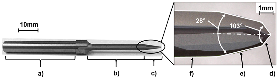
WC-Co drill for CFRP drilling: (a) drill shank side, (b) reamer cutting side, (c) drill cutting edge side, (d) primary cutting edge, (e) secondary cutting edge, and (f) tertiary cutting edge.
Deposition of diamond coatings
Before diamond deposition, the selected drills were pretreated. The frequently used chemical etching method was optimized for selected substrates and included several steps of etchings with Murakami reagent and nitric acid solution. Then, the etched drills were seeded with diamond seeds ≈4 nm of average particle size by ultrasonically in a suspension of diamond powder in purified water.
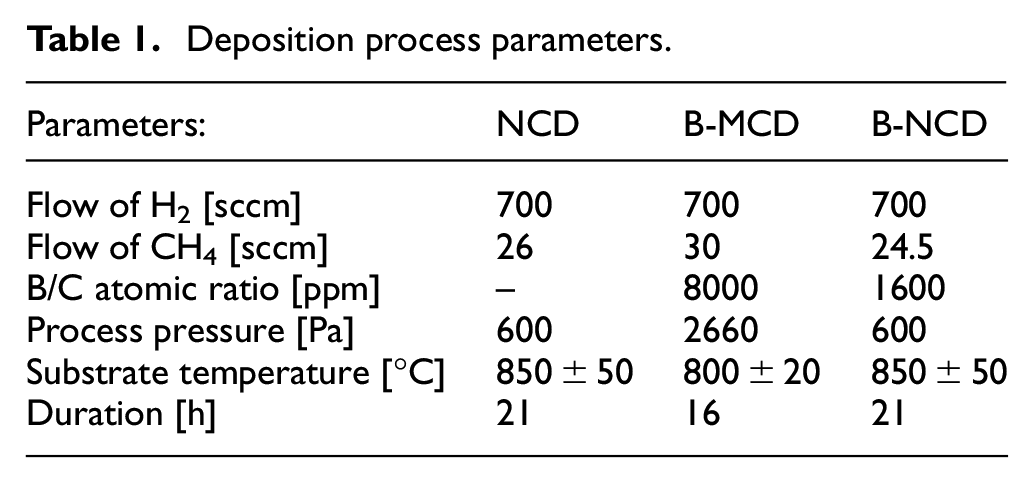
The three types of required diamond coatings, boron-doped MCD (B-MCD), boron-doped NCD (B-NCD), and undoped NCD (NCD), were grown on the WC-Co substrates using the hot filament chemical vapor deposition (HFCVD) method in an industrial hot-filament reactor (ShinMaywa Co.). A mixture of CH4 and H2 was used as precursor gas in the main growth and nucleation deposition process stages. Boron species were incorporated into the coating during the growth process stage by adding a mixture of an evaporated liquid solution of trimethoxyborane ((CH3O)3B) with acetone and H2. A controlled evaporation mixer was employed for the preparation of the gas-liquid mixture. Common deposition parameters are shown in Table 1. A more detailed description regarding applied equipment and the HFCVD process was referred to in our previous study. 20
Deposition process parameters.
As a result, the required types of diamond coating with a film thickness of about 8 µm were deposited on all tested drills. Then the deposited layers were examined in terms of surface morphology, grain sizes by scanning electron microscope (SEM JEOL JSM5510), and carbon structure by Raman microscopy (RAMAN-11, NanoFoton). Coating surface roughness was measured by a laser microscope (OLS4100, OLYMPUS). Indentation tests were carried out to evaluate adhesion strength between the deposited coatings and WC-Co (Rockwell hardness testing machine ARK-600, Mitutoyo).
Drilling tests
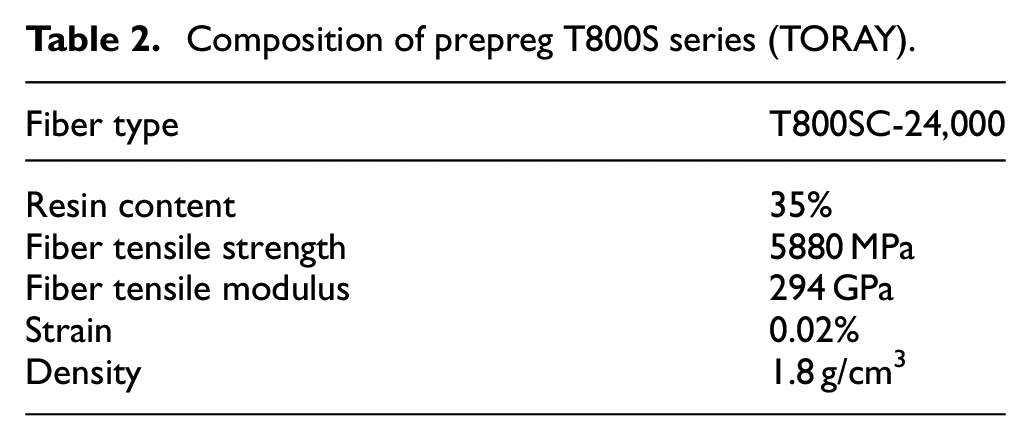
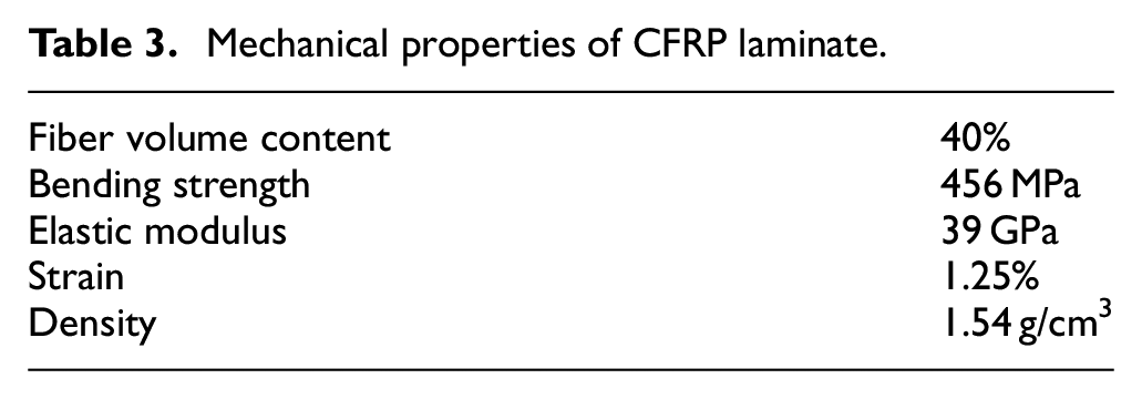
In this study, CFRP laminates with a thickness of 8 mm and dimensions 250 mm x 100 mm were used as workpieces. The workpiece consists of 42 unidirectional layers of prepreg (T800S series, TORAY) with quasi-isotropic laminate lay-up. The carbon fiber volume ratio was about 40%. The composition of applied prepreg and mechanical properties of CFRP laminate is presented in Tables 2 and 3.
Composition of prepreg T800S series (TORAY).
Mechanical properties of CFRP laminate.
All drilling tests were performed using a vertical milling center OKUMA MD-45VA with the following cutting parameters: feed rate ƒ = 0.06 mm/rev, drill rotation n = 8000 rpm with corresponding cutting speed V = 82.4 m/min. These cutting parameters already utilize for machining CFRP commercial products by the NCD coated one-shot drills applied in the current study tests. No coolant was used during the tests. The experimental setup for the drilling tests is shown in Figure 2. For comparison of cutting performance, non-coated WC-Co drills were applied as well. Their drill shapes, angles, and dimensions are identical to the coated drills. The cutting performance was evaluated through the drilling of series of consecutive holes in the workpiece. During the experiments, thrust force and torque were measured using a rotating dynamometer “Kistler 9125A” with a charge amplifier “Kistler 5237” and monitored on a personal computer using data acquisition software DynoWare 2.5. In addition, drill flank wear was measured periodically using a digital microscope VHX-1000SP (Keyence).
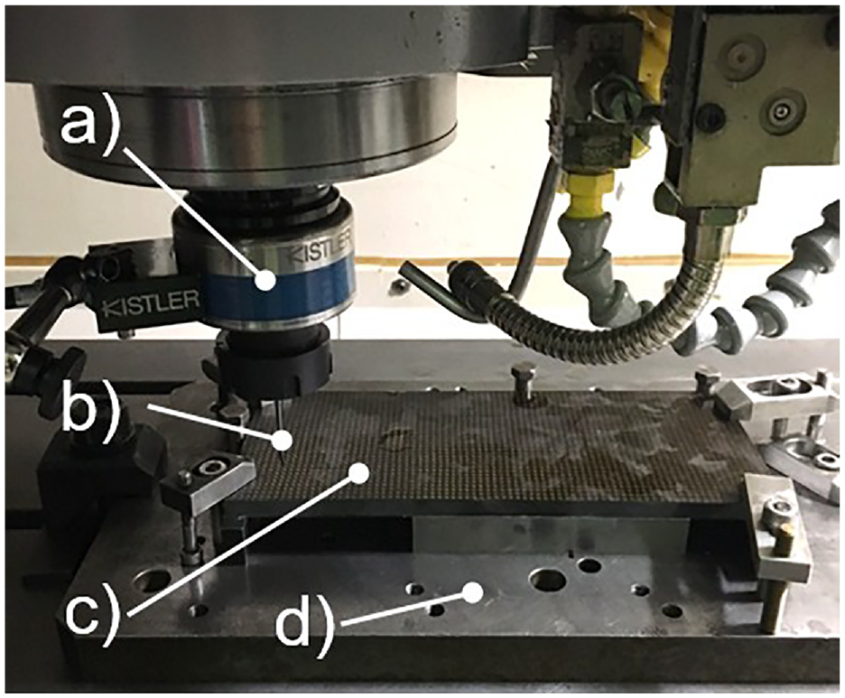
Experimental setup for drilling tests: (a) dynamometer, (b) tested drill, (c) CFRP workpiece, and (d) fixture.
Experimental results and discussion
Characterization of deposited diamond coatings
SEM images of the surface morphology of the diamond-coated drills are shown in Figure 3. Figure 3(b) shows that the undoped NCD coated drill has a smooth film surface with ultrafine grains, which are not clear resolvable with the applied magnification of used SEM. On the other hand, Figure 3(c) shows the morphology of the B-MCD coated drill. With an average size of ≈2 µm, randomly oriented faceted diamond grains were observed at different points of cutting edges of the drill. Further, Figure 3(d) shows an SEM image of the B-NCD coated drill with the smooth wavy surface of ultrafine grains.
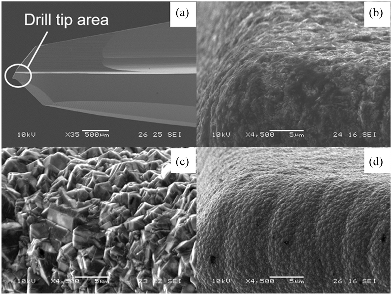
SEM images of surface morphologies observed on drill tip area of the coated drills (a) for: (b) NCD, (c) B-MCD, and (d) B-NCD coatings.
In continuation, Figure 4 shows diamond surface morphologies observed on the flank area of the coated drills by the laser microscope. Compared the surfaces shown in Figure 4(a) and (c), a significant distinction between the NCD and B-NCD diamond films can be seen. The B-NCD film has a homogeneous smooth surface with low visible fine ballas grains. In contrast, the NCD film shows a non-uniform surface with larger ballas grains. The observed phenomenon can be described difference in the deposition process parameters. Application liquid solution of trimethoxyborane with acetone for boron doping increased the oxygen/carbon ratio during the growth duration of the B-NCD film and provided decreasing in the grain size. The B-MCD film, as shown in Figure 4(b), exhibits a uniform rough surface with sharp grains. After, diamond film surface roughness was measured in different points of the coated drills, and the average value of the roughness was considered. Surface texture parameter Sa, as arithmetical mean height, based on ISO 25178 “Surface Texture,” is applied for evaluation. The scan size was determined by the optical magnification of the system (100×) in resulting surface area of 129 µm × 129 µm. The B-MCD coated drill has a rough surface with a Sa value around 340 nm due to large and faceted micro-sized diamond grains. However, the Sa values of the nano-sized diamond surfaces are near 131 nm of NCD and 74 nm of the B-NCD coated drills, respectively, due to the film’s grain refinement.
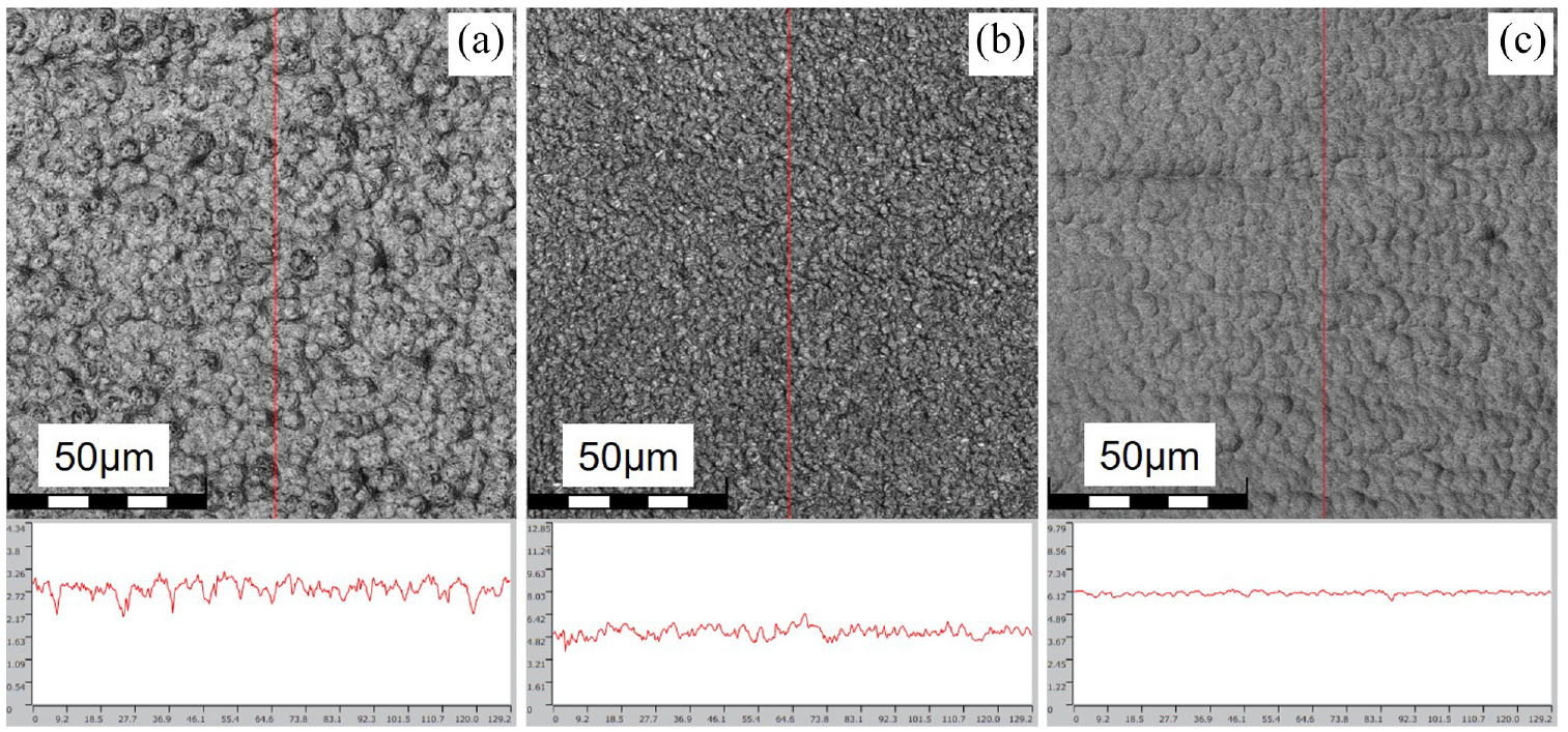
Topographic images with surface profiles, observed on a flank area of cutting edge, for: (a) NCD, (b) B-MCD, and (c) B-NCD coated drills, respectively.
Raman spectra of the deposited diamond coatings are displayed in Figure 5. In the Raman spectra of the NCD coating, several visible peaks can be identified. The peak at 1337.3 cm−1 is a small diamond peak, while the peaks at 1385.6 and 1550 cm−1 are D and G peaks of amorphous carbon, respectively. 21 Then, two peaks, as 1152 and 1489.2 cm−1, are confirmed to trans-polyacetylene. 22 Regarding the B-MCD coating, the Raman spectra show two broad peaks at 500.7 and 1223.8 cm−1 associated with boron doping. Also, it shows the diamond peak at 1329.1 cm−1, and G peak at 1532 cm−1 as amorphous carbon.23,24 On the other hand, Raman spectra of the B-NCD coating show a relatively weaker peak at 517.8 cm−1 and not a clear visible peak near 1200 cm−1 compared with the B-MCD coating. Such difference may be caused by lower boron incorporation in the B-NCD film due to the low B/C atomic ratio during the deposition process. Besides associated with boron doping peaks, the Raman spectra of the B-NCD coating have a diamond peak at 1335.3 cm−1, D and G peaks at 1360.5 cm−1, and 1561.4 cm−1, respectively. Also, two peaks associated with trans-polyacetylene at 1140.9 and 1472.1 cm−1 were observed.
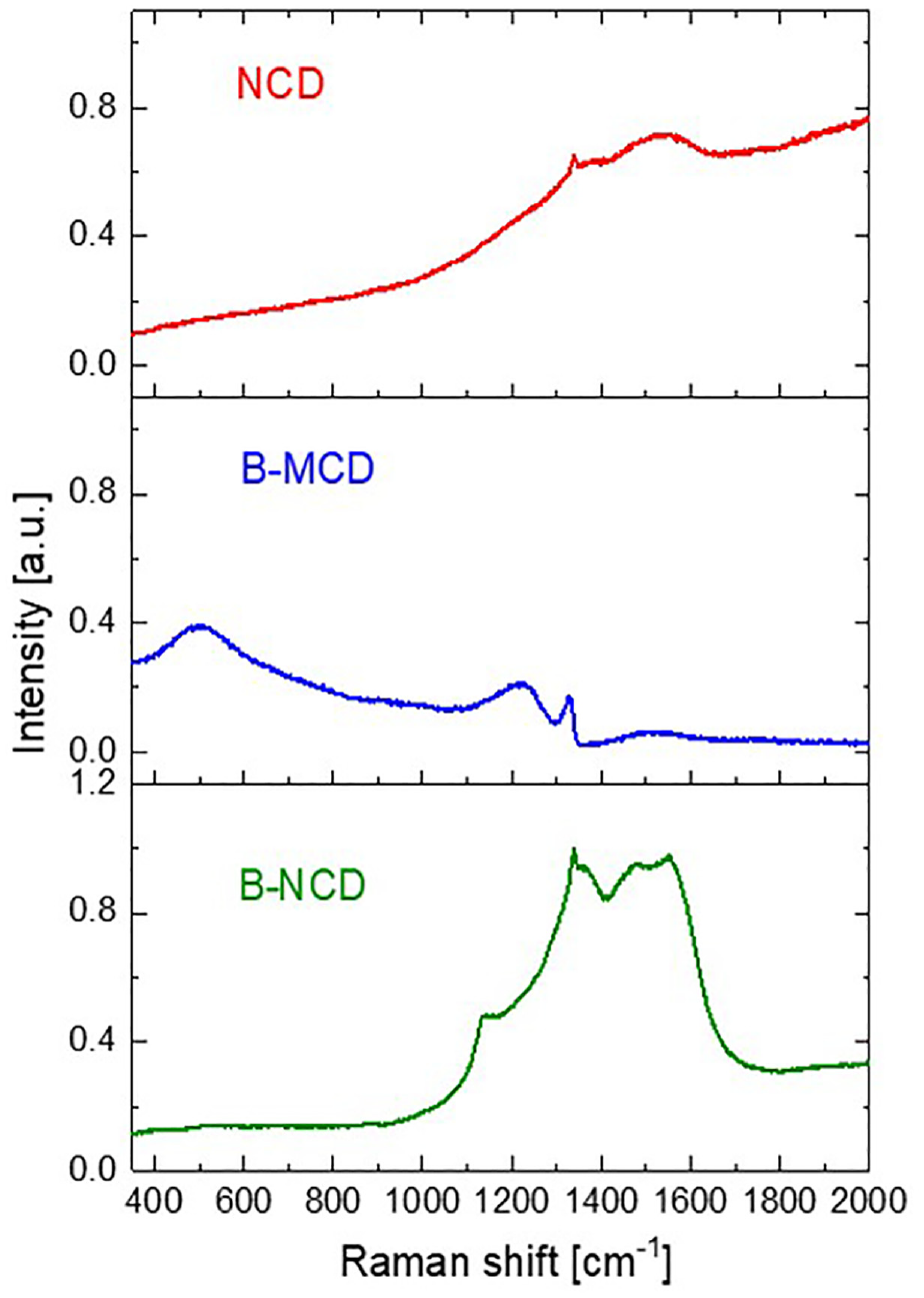
Raman spectra of NCD, B-MCD and B-NCD coated drills, using green (λ = 532 nm) excitation.
It is well-known that in the Raman spectra of a diamond coating, the peak close to 1332.4 cm−1 means the typical peak of the sp 3 diamond phase of the natural diamond without residual stress. The shift of this peak relative to 1332.4 cm−1 indicates residual stress in the coating. Estimation of the residual stress value in the diamond coating based on the Raman spectra can be done with the method described in the research of Ralchenko et al. 25 According to this method, compressive residual stresses with value −2.77 and −1.64 GPa were calculated in the NCD and the B-NCD coatings respectively. On the other hand, the B-MCD coating has tensile residual stress of +1.87 GPa. It should be noted that the residual stress value of both boron-doped diamond coatings is lower than that of the NCD one. Such phenomenon could be explained, that the covalent radius of boron atom (0.085 nm) is larger than the radius of carbon atom (0.077 nm), and accordingly may induce tensile residual stress in the doped diamond film. 26
In order to evaluate the adhesive strength between the deposited diamond coatings and the drill’s substrate, indentation tests were carried out using a Rockwell hardness testing machine with a diamond indenter, which has a conical angle of 120° and radius of curvature at the tip 0.2 mm. Each diamond coated drill was tested under the load of 1471 N. It should be noted that applied drill shape with planar faces allows performing the indentation tests directly on it. Figure 6 shows SEM images of surface morphologies of the coated drills after indentation tests. For the NCD coated drill, a large area of coating peeling around the indenter trace was observed. Compared with the NCD coated drill, the peeled areas on B-MCD and B-NCD coated drills were relatively more minor. On the other hand, the B-NCD coating does not show an advantage in adhesion, although it has the lowest residual stress among the tested diamond films. For incomplete agreement, other reasons for such adhesion phenomenon can be proposed. Wang et al. 27 reported in their study that boron-doped NCD film, in which the compressive residual stress is lower than in undoped MCD film, shows a larger film removal area compared to the undoped MCD due to its poor mechanical cohesion. Therefore, a reduction in the residual stress caused by boron doping cannot compensate for the influence of diamond film impurities on its adhesion.
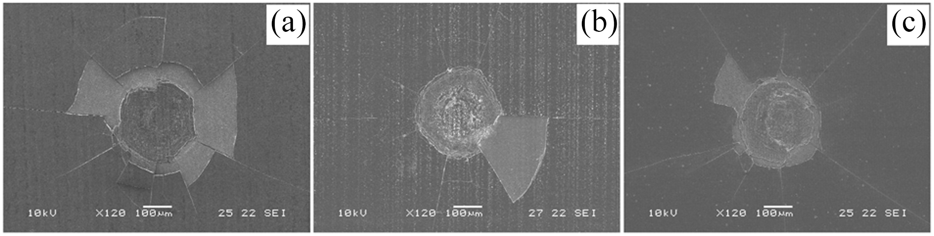
SEM images of indentation morphologies, obtained by Rockwell testing machine with a load of 1471 N, on: (a) NCD, (b) B-MCD, and (c) B-NCD coated drills, respectively.
Based on the Raman spectra characterization and indentation test results, it can be concluded that the adoption of boron can enhance the adhesion between the diamond films and the WC-Co substrates.
Drill flank wear evaluation
Usually, tool wear performance reflects the tribological and physical properties at the tool-workpiece interface in the actual cutting process and is a critical point in the tool life durability and cutting performance. In the drilling tests, tool wear was evaluated as maximum flank wear land width (VBmax) as a function of drilled hole number, as shown in Figure 7. The results, shown in Figure 7, indicate that progress of the VBmax values for all diamond coated drills can be divided into three typical stages, as the initial wear under drilling ∼150 holes, gradually increased wear between ∼150 and 500 of drilled holes and rapid wear stage, respectively. On the other hand, flank wear progresses of the non-coated WC-Co drill is dramatically increased and achieved a value of 0.1 mm after drilling 300 holes. Then drilling test with the drill was stopped due to poor drilled hole quality, described in the following section.
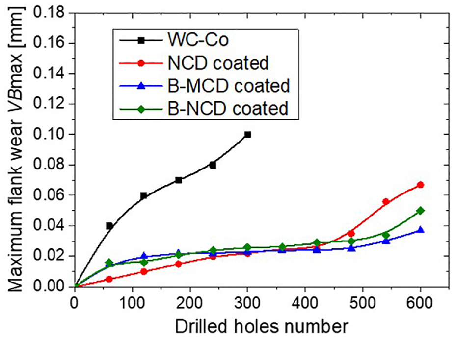
Variations of maximum flank wear as a function of drilled holes number.
Some minor differences between the flank wear values associated with their different diamond coating properties were observed until achieving 500 holes regarding the diamond-coated drills. Hereafter, the flank wear values have rapidly increased, especially for NCD and B-NCD coated drills, while the B-MCD coated drill kept a lower flank wear value. Previous cutting tests confirm that coating peeling occurs for the diamond-coated drills during the drilling duration. The diamond film begins to peel off, depending on the applied load upon the film surface and the film-substrate adhesion. According to the impact dynamic models based on Hertz’s theory of contact, continuous or intermittent impacts on the coated cutting edge can induce shear stress and minor cracks beneath the film surface. Because adhesion of the diamond film and the substrate is weaker than inside the same material, the formation and propagation of cracks along with the film-substrate interface during the drilling of CFRP occurs. Moreover, the thickness of the diamond films is decreased during drilling under the abrasive effect of the carbon fibers, and, therefore, film durability against crack propagation is reduced as well. Thus, enhanced film-substrate adhesion is essential for increase the tool lifetime. In contrast, abrasion of the edges due to the hard carbon fibers without observed chipping or micro-fracture is seen as the predominant wear mechanism on the non-coated WC-Co drills. The cobalt binders have removed during drilling, and many carbide grains dislodged out from the tool surface. Moreover, the tool wear phenomena that were observed in this study are in good accordance with references.13,28
Figure 8 shows the wear morphologies of the diamond-coated drills after drilling 600 holes. For NCD coated drill, the diamond film was removed along the cutting edge under the cutting, and the worn substrate has been observed clearly, as shown in Figure 8(a) and (b). On the other hand, for both boron-doped diamond coated drills, the worn diamond films with localized film flaked areas are visible, as shown in Figure 8(c) to (f). Moreover, the B-MCD coated drill showed an advantage in the tool wear durability. This phenomenon could be attributed to enhanced adhesion between the diamond film and WC-Co substrate by application of appropriate boron doping level. 29
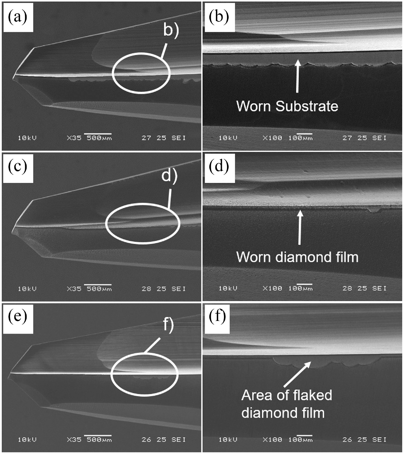
SEM images of the drills after drilling 600 holes: (a, b) NCD coated drill, (c, d) B-MCD coated drill and (e, f) B-NCD coated drill.
Thrust force and torque evaluation
It is known that a thrust force and torque induced during drilling are key factors that influence CFRP hole quality. The source of these cutting forces may be a combination of two factors. First is the drilling resistances, including the composite’s matrix shear force and fiber breaking resistance, generated when drilling the workpiece. The second factor is frictional resistances, which occur between the tool’s surfaces and the hole’s sides of CFRP. As already reported, that tool wear behavior mainly influences the thrust force and the torque values through increased cutting edge rounding under abrasive action of the CFRP fibers. Further, cutting edge with large roundness has provided more significant cutting force by increasing the feed direction’s contact area. Therefore, the thrust force and torque have high sensitivity to tool flank wear.
Figure 9 shows thrust force variations as a function of drilled holes number. Thrust force induced by the WC-Co drill increased dramatically as the number of holes increased, which correlated with flank wear results shown in the previous section. On the other hand, thrust forces induced by the NCD and B-NCD coated drills have increased until ∼200 drilled holes. Further, the forces gradually decreased to the rest of the tests. In comparison, the thrust force induced by the B-MCD coated drill is progressively reduced during the drilling test. Such results could be associated with epoxy matrix softening effects from cutting heat caused under dry friction between diamond surfaces of the coated drills and CFRP workpiece. Xu et al. 9 described the CFRP matrix softening effect in their study. The difference with approximate value ∼5 N has occurred between thrust forces induced by the NCD and B-NCD coated drills, as shown in Figure 9. That can be assumed due to the difference in coating surface roughness. Rougher surfaces of the NCD coated drill, especially in drill flutes, hindered evacuating CFRP chips from the hole outward.
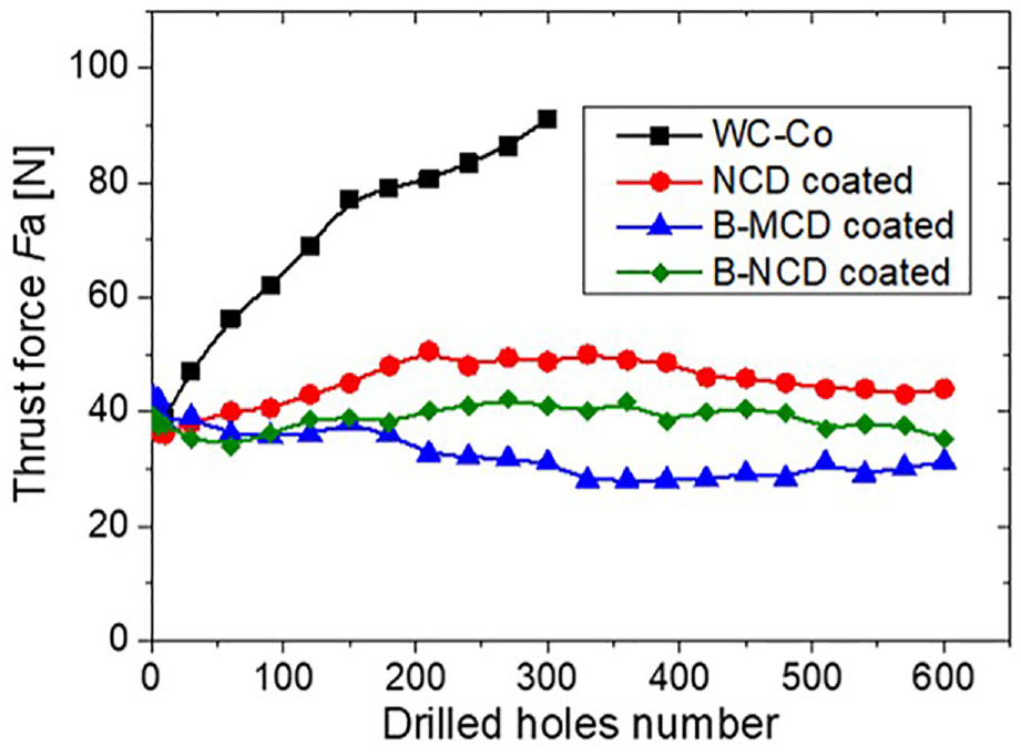
Variations of the thrust force as a function of drilled holes number.
Figure 10 shows torque induced by the examined drills as a function of drilled holes number. As shown in Figure 10, the torque values are not increased significantly during the drilling tests, except for the WC-Co drill, and they have almost similar trends with the thrust forces. Also, the torque curves have sensitivity to friction effects between the hole surface and CFRP chips accumulated in flutes of the examined drills.
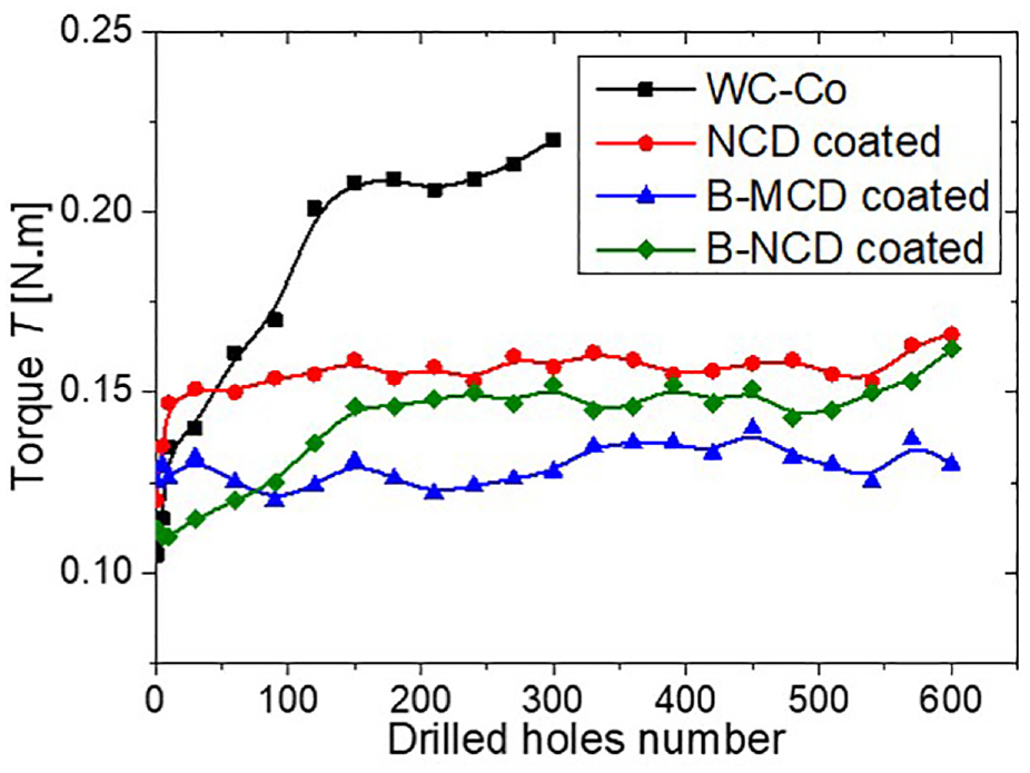
Variations of the torque as a function of drilled holes number.
It can be suggested that the diamond-coated drills have produced lower thrust forces and torque values compared with the non-coated drill. The B-MCD coated drill produces the lowest thrust force and torque compared to the coated drills.
Hole quality evaluation
During machining of CFRP laminates, drilling-induced delamination commonly occurs at the hole entry and hole exit of the drilled hole periphery. According to the formation mechanism, the hole entry damage is usually named peel-up delamination, while the hole exit damage is called push-out delamination.6,30 In this study, both types of CFRP delamination induced by the compared drills were evaluated through the method proposed by Babu. 30 Delamination factor Fd is defined as the ratio of the maximum diameter of the damaged zone (Dmax, mm) to the nominal diameter of the hole (D, mm), and two circles are concentric, as shown in Figure 11. Then the value of Fd is expressed as:

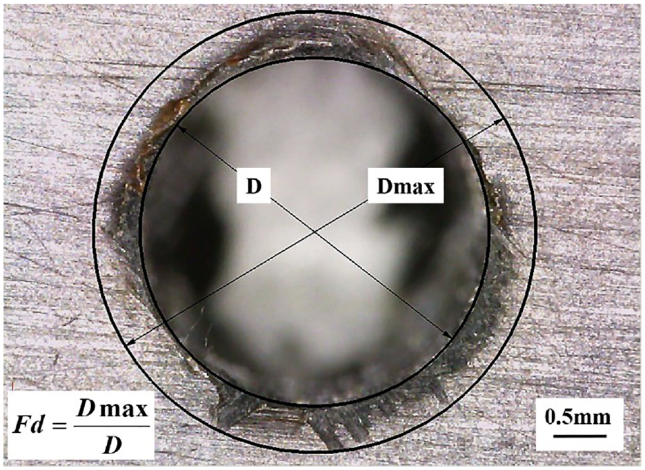
Schematic diagram of delamination factor (Fd).
The maximal diameter of the damaged zone around each hole was measured with a digital microscope VHX-1000SP (Keyence). Figure 12 shows a variation of measured delamination factor (Fd) at hole entry of the laminates as a function of drilled hole number. While Figure 13 shows the variation of the delamination factor at hole exit sides of the laminates as a function of drilled hole number. These figures show an approximately similar trend for peel-up and push-out delamination with different values of the delamination factors. Also, as shown in Figures 12 and 13, the peel-up and the push-out delamination have high sensitivity to the drills’ flank wear progress. This relationship can be explained as follows. The tool wear progress provided increasing loading through the growth of thrust force and torque during drilling. Subsequently, when the loading exceeds the interlaminar fracture toughness of the laminates, then delamination occurs. Moreover, the peel-up delamination trend has correlated to the torque values of the tested drills. In contrast, the push-out delamination close related to the thrust forces induced by the tested drills.
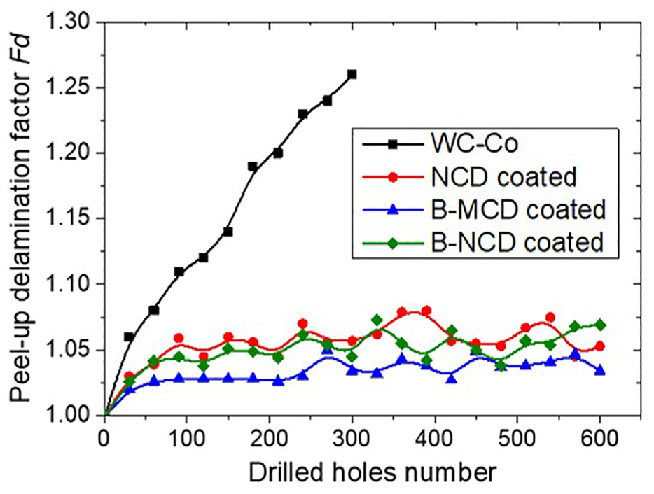
Variations of the delamination factor on entry hole side as a function of drilled holes number.
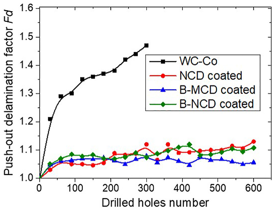
Variations of the delamination factor on exit hole side as a function of drilled holes number.
Besides peel-up and push-out delamination, push-out burr appearance on drilled hole exit is unacceptable defects of CFRP laminates. 31 Used method for determination of Fd does not evaluate the value of the push-out burrs. Therefore, in this study, the push-out burrs were assessed through the digital microscope observation only. Figure 14 shows the images of the hole’s exits drilled by the compared drills. Many uncut push-out burrs were induced after drilling by the WC-Co drill, as shown in Figure 14(a). Because, during drilling, wear of cutting edges has occurred, and carbon fibers could not be cut off. Furthermore, severe push-out delamination with the melting of resin bond was observed on the CFRP laminate’s hole exit side. Such a phenomenon suggested that worn cutting edges of the WC-Co drill generated cutting temperature, exceeding the resin bond’s glass transition temperature. 32 However, for the holes that produced the diamond-coated drills, shown in Figure 14(b) to (d), only some uncut burrs were observed. The least burrs, shown in Figure 14(c), are observed on the hole exit produced by the B-MCD drill. Such difference in hole quality could be attributed to the drill’s lower flank wear value compared with the NCD and B-NCD coated drills.
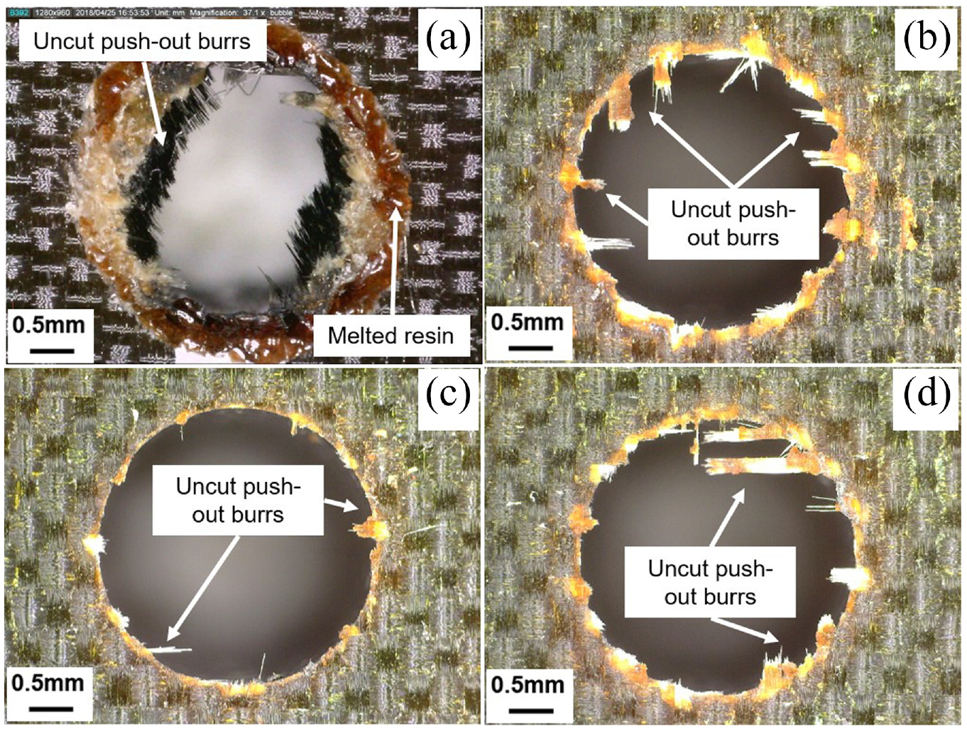
Images of CFRP hole exit: (a) 300th hole made by WC-Co drill and 600th holes made by NCD (b), B-MCD (c), B-NCD (d) coated drills, respectively.
Regarding the hole’s size comparison, drilled hole sizes were measured with a gauge plug of a nominal diameter of 3.28 mm. The gauge passes through all holes drilled by diamond-coated drills. In the case of the WC-Co drill, the gauge did not go through since the 27th hole. As lower flank wear values of the diamond-coated drill’s cutting edges keep the drilled holes into the tolerance zone of the required size, results can be explained compared with WC-Co drill’s edges. Therefore, holes made by the WC-Co drill leave the tolerance zone soon due to the tool wear.
Based on the above evaluations, it is suggested that holes produced by the B-MCD coated drill have the best quality in terms of the delamination and push-out burrs appearance.
Conclusions
In this study, the effects of boron-doped and undoped diamond coatings on the cutting performance of WC-Co drills in drilling CFRP laminates have been experimentally investigated. Main conclusions obtained as follows:
(1) Experimental results indicated that boron doping of diamond coating enhanced adhesion strength between the coating and WC-Co substrate of the drill.
(2) Drilling test results show the advantage of the B-MCD coated drill in terms of the flank wear, the thrust force, and torque compared with the NCD and B-NCD coated drills.
(3) The delamination factor (Fd) correlates with the thrust force and the torque induced by the compared drills. All diamond-coated drills generate stable peel-up and push-out delamination factors. On the other hand, delamination factors produced by the WC-Co drill were dramatically increased. It confirms the benefit of the application of diamond coating for tools when drilling CFRP laminates. Moreover, B-MCD coated drill had generated the least push-out burrs between the tested drills.
Footnotes
Appendix
Declaration of conflicting interests
The author(s) declared no potential conflicts of interest with respect to the research, authorship, and/or publication of this article.
Funding
The author(s) received no financial support for the research, authorship, and/or publication of this article.