
Abstract
This paper presents a design method for manufacturable casting parts based on topology optimization of structural assemblies, which considers the geometry requirement and the manufacturing constraint of die-set material cost. The problem formulation follows the previous work presented in multi-component topology optimization for stamped sheet metal assemblies (MTO-S). Based on the vector method combined with Heaviside function, the moldability constraints for casting parts is formulated. As the base structure of component is easily misidentified as an undercut structure by the moldability constraints in the structural assemblies, the component baseline is proposed to realize the automatic filtering of the “fake” undercut structures which can be extended to the parting line to obtain the form of two-mold design. Several numerical examples on compliance minimization of single-mold and two-mold casting parts are conducted to verify the validity of the proposed method. The optimized results show that there is no interior void for each component and the component manufacturability has been improved obviously. The setting of minimum-area bounding box (MABB) area constraint limits and the number of components will have a significant effect on the performance of the optimized structure. Users can achieve the desirable solution based on their actual demand by making trade-offs between the structural performance and manufacturing cost.
Keywords
Introduction
As an efficient structure design method, topology optimization technology has made great progress since Bendsøe and Kikuchi presented the homogenization-based approach in 1988 and various approaches of topology optimization have been proposed.1–4 By using topology optimization technology, a light-weight structure can be obtained with the structural stiffness, strength, and some other satisfied performance. 5 Topology optimization has been widely used in the structural design of various industries such as mechanical design, biomedical, automotive, and composite materials.6–9 Compared with the conventional trial-and-error design process, topology optimization can provide engineers with different design directions in the early design stage of products and help to meet the requirements of manufacturing cost, process, and other characteristics while ensuring the structural performance of the product. By implementation of topology optimization, the efficient and rapid design can be achieved as well as the considerable cost savings. 10
However, topology optimization technology has several limitations in engineering application, mainly for poor manufacturability of topology optimization solutions. Firstly, in order to meet the requirements of structural performance and styling, the overall structures of products always ask for complex geometries. And with the consideration of cost control, the overall structure of products are always the assemblies of multiple components with relatively simple geometries. However, most related research and commercial software applications in the field of topology optimization are conducted in the single-component environment. A single-component product with complex geometry is less economical and lack of manufacturability. Therefore, comparing with the single-component product in most current research, the product with multiple component assemblies is more suitable to the requirements in practical industrial production. It is of great significance to achieve simultaneous optimization of structural topology and component decomposition.
Recently, some attempts and explorations have been fulfilled on topology optimization in multi-component environment. The conventional structural design method considering components assembly, known as a two-step approach, is to optimize its entire geometry in single-component environment first, and then decompose it by refining component boundaries and joint configurations. The two-step approach is likely to yield sub-optimal solutions with respect to entire structural performance, manufacturing, and assembly costs. The optimized decomposition obtained in the second step is largely dependent on the entire geometry obtained in the first step and the optimization algorithms applied in the above literature are mainly non-gradient methods.11,12 Due to the lack of sensitivities and the associated computational inefficiency, non-gradient methods received some critiques from the topology optimization community regarding its applicability in continuum structure problems. 13 Since 2018, Saitou and his group presented a gradient-based multi-component topology optimization method enlightened by the previous study and expanded it in the fields of traditional process, additive manufacturing, and composite materials, enriching the original research content.14–17
Secondly, it is difficult to convert topology optimization solution into process feasible solution and the interpretation for topology optimization solution is regarded as the main method at present. However, the modification for feasibility may break the balance between performance and cost which is provided by topology optimization and result in large deviations between initial design and final design which stand for that the final design is no longer the optimal one. Therefore, adding manufacturing constraints during topology optimization will greatly improve the manufacturability of solutions.
The manufacturing constraints can be divided in two types generally: the geometry requirement constraint and the manufacturing cost constraint.18,19 For the geometry requirement constraint, such as geometric features of a part design should be properly aligned with certain directions in order to be manufacturable in casting, forging, and machining (the tool approaching directions for machining, parting directions for casting/molding, and punching direction for forging) 20 ; the extrusion process requires that the section of the part along the extrusion direction is consistent. 18 After years of research efforts, the geometry requirement constraints such as those mentioned above can be added to the topology optimization process to improve the manufacturability.15,21 For the manufacturing cost constraint, several studies have been conducted to achieve the control of manufacturing cost: Martin Baumers estimated a set of specific cost indices to evaluate the cost of additive manufacturing in detail. 22 Azamirad and Arezoo designed stamping die by topology optimization which significantly reduce material volume and maximum displacement compared with the standard die. 23 As a traditional process, two types of manufacturing constraints mentioned above are under the consideration for casting parts. Therefore, casting parts are chosen as the research objects and in view of the lack of consideration of structural assembly and manufacturing constraints in topology optimization, a manufacturable casting parts design with topology optimization of structural assemblies is presented in this paper.
The rest of paper is organized as follows. In Section 2, gradient-based multi-component topology optimization for stamped sheet metal assemblies (MTO-S) is briefly introduced. In Section 3, the two types of the manufacturing constraints for casting parts are discussed, respectively. Component baseline function is presented to realize the automatic filtering of the “fake” undercut structures and the formulation for manufacturable casting parts design with topology optimization of structural assemblies is proposed as well. In Section 4, some numerical examples are provided to verify the applicability of the proposed method. Finally, Section 5 summarizes the current study and opportunities for future work.
Gradient-based multi-component topology optimization for stamped sheet metal assemblies (MTO-S)
In 2018, Zhou and Saitou
14
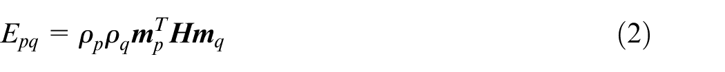
presented a continuous relaxation formulation of multi-component topology optimization to attain the simultaneous optimization of a base structural topology and its decomposition. The initial continuous design domain is discretized in the manner shown in Figure 1(a) and there are three types of elements illustrated: the traditional square structural element, the thin strip element denoted as Type A joint and the smaller square diagonal element denoted as Type B joint. As shown in Figure 1(c) and (d), the equivalent Young’s modulus of Type A joint is expressed as
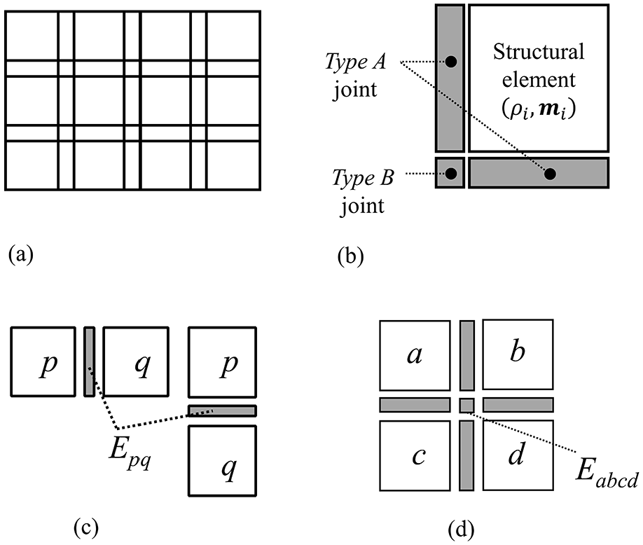
Domain discretization and definition of two different types of joint elements 15 : (a) Discretized design domain, (b) structural and joint elements, (c) Type A, and (d) Type B.
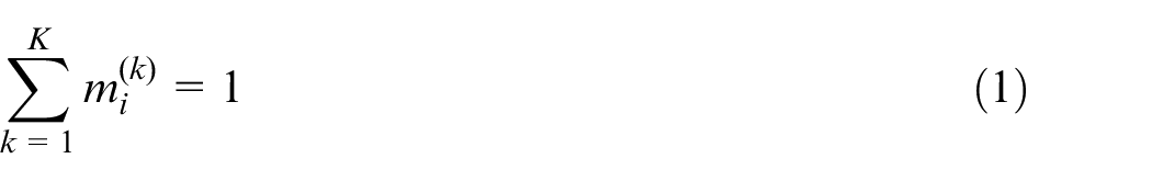
Based on the solid isotropic material with penalization approach (SIMP), this methodology introduces component membership
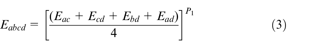
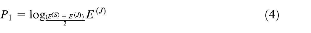
As the joint element is not allocated any design variables, the Young’s modulus of two types of joint elements is calculated by the Young’s modulus of adjacent structural elements or joint elements. The expressions of Young’s modulus of two types joint elements can be calculated as equation (2) and (3), where
In MTO-S, the cost constraint is the only manufacturing constraint as there is no explicit geometry requirement for stamped sheet metal products. The cost constraint mainly includes the cost of die-set materials
Manufacturable casting parts design with topology optimization of structural assemblies
Moldability constraints for casting parts
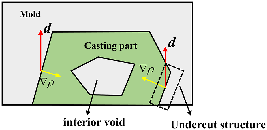
To ensure that casting parts can be removed from molds smoothly, namely moldability for casting parts, casting process requires the geometry of casting parts to meet certain conditions: (1) interior void is forbidden in the structure. (2) The amount and the angle of undercut geometry should be decreased as much as possible. Figure 2 shows a single-mold casting parts with interior void and undercut structure. It can be observed that the interior void appearing inside casting parts will result in that the core cannot be taken out after the cooling and solidification of molten metal. Moreover, the undercut structure will prevent the casting parts from being separated along the given drawing direction.
Moldability constraint for casting parts.
In order to satisfy the two geometry requirements mentioned above, there are about three effective methods in literature: gradient-descent method, vector method, and fictitious physical model method.24–26 To simplify modeling process and ensure the efficiency of optimization, the moldability constraint in this paper is modeled based on the vector method with Heaviside function. 27
As shown in Figure 2,
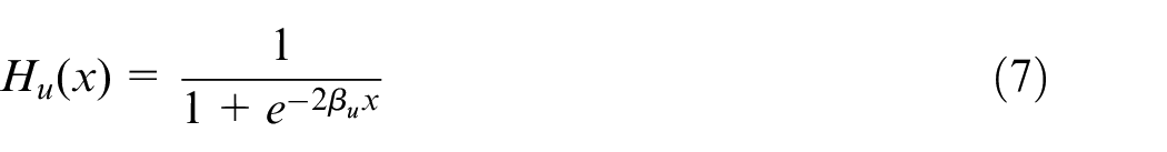
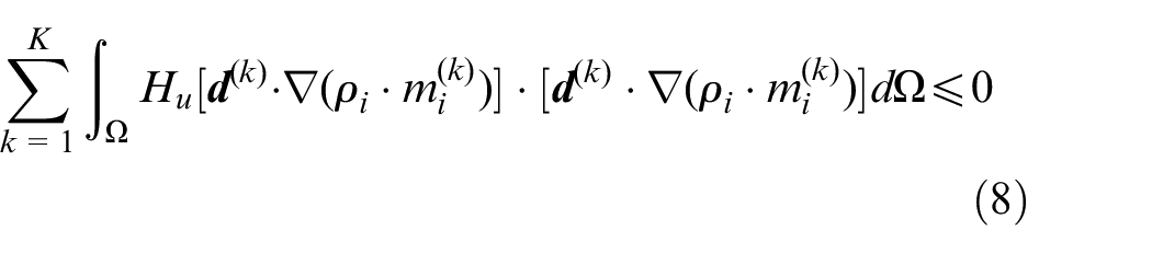
Due to the non-positive of non-undercut structure, it is not expected to be included in the calculation process of undercut structure in the overall design domain. Otherwise, a large number of undercut structures will occur in the final design. Hence the Heaviside function is introduced to filter out the non-undercut structure. The specific form of the Heaviside function used for undercut structure is shown in equation (7). The value of this function is between 0 and 1 and as the power parameter
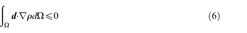
As the components are generally independent of each other, the drawing direction of each component
In equation (6),
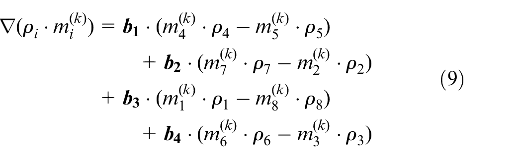
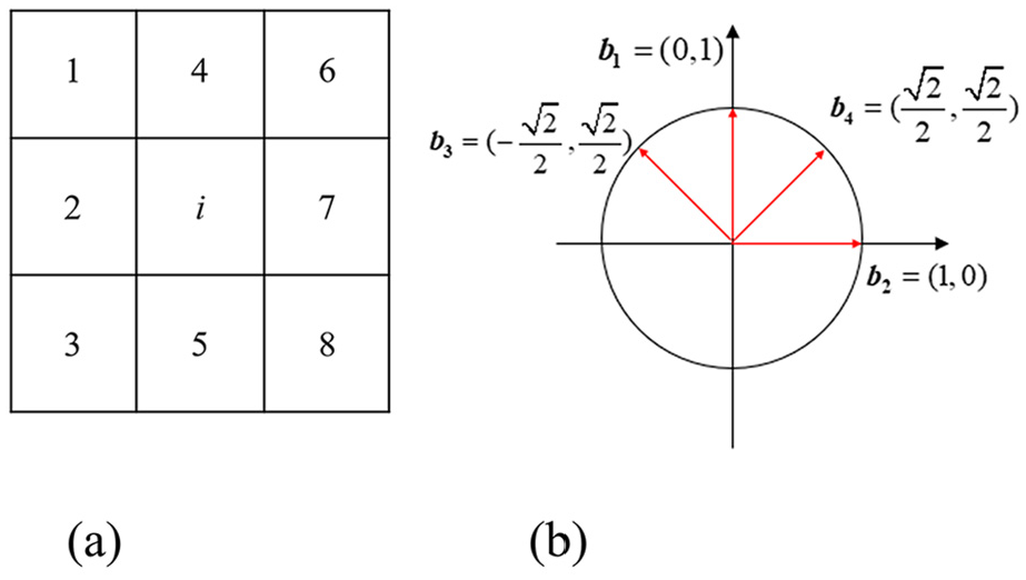
Density gradient: (a) 3 × 3 mesh and (b) four unit vectors.
Component baseline function
Based on the method mentioned above, the density gradients of the boundary elements in design domain cannot be evaluated as the 3 × 3 meshes cannot be established on the boundary. As the boundary of design domain is easy to be a part of a component with topology optimization of structural assemblies, it is important to detect the density gradient of the boundary elements. To calculate the density gradients of boundary elements, it is assumed that there is a circle of empty elements around the design domain to establish 3 × 3 meshes.
However, with the introduction of boundary detection, there is another problem in the optimized results. Figure 4 shows the optimized result of a single casting part. The drawing direction is vertically upward, and the density gradient (red arrows) of component base structure is consistent with the drawing direction. Therefore, the component base structure located at the bottom of the design domain has been misidentified as the undercut structure. This misidentification is caused by the introduction of boundary detection and will be more common in structural assemblies.
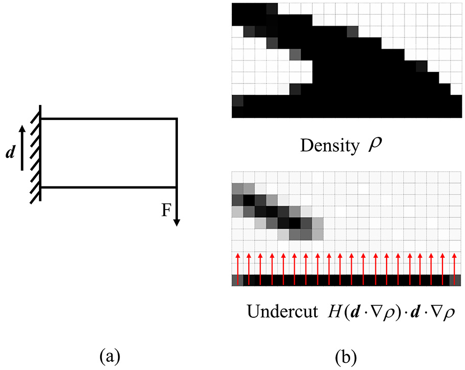
The misidentification of component base structure:(a) boundary condition, (b) optimization result and undercut structure.
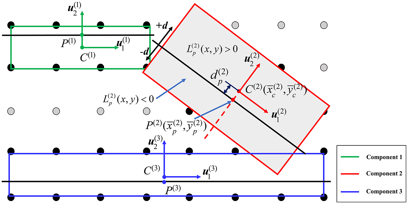
In order to avoid the misidentification of component base structure, the component baseline function is introduced in this paper. It should be noted that in order to make the following study convenient, it is assumed that the minor direction of the minimum-area bounding box (MABB) mentioned in Section 2 which is a rectangle enclosing each component is the drawing direction. And correspondingly, the direction of component baseline function is the major direction of the MABB. As shown in Figure 5,
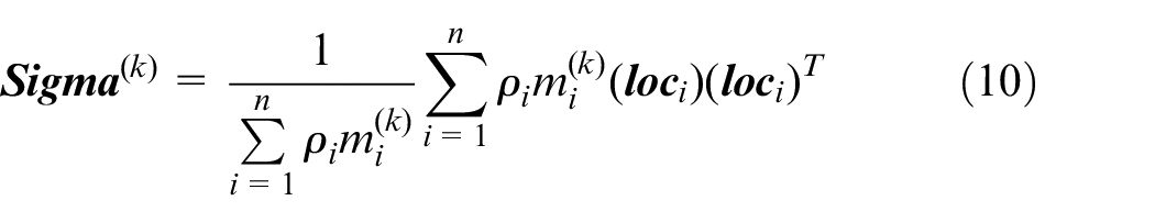
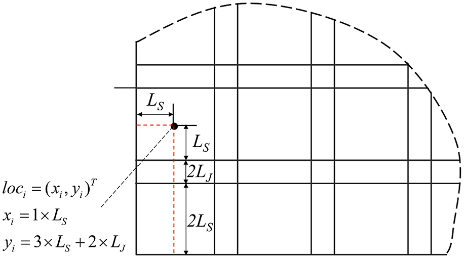
Definition of the location
Figure 6 shows the calculation method of the coordinate of a point on the component baseline with a three-component example. The center point of MABB for component k is denoted as C(k) and the point on the component baseline is denoted as B(k). As the C(k) and B(k) have the same projection on
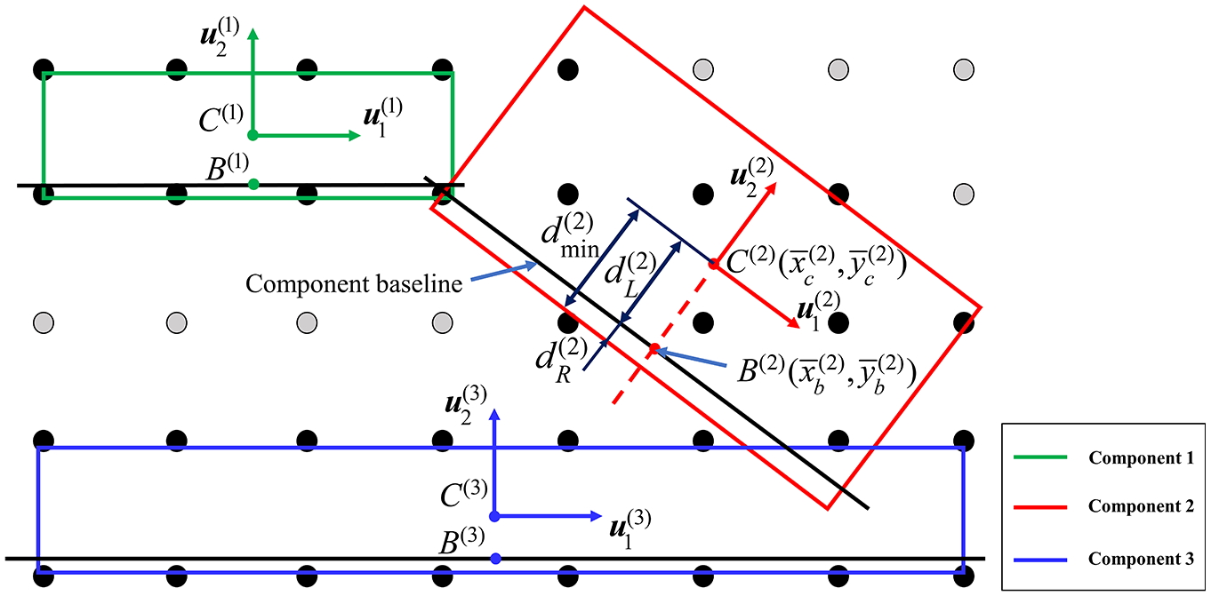
The calculation of the component baseline point.
In order to achieve the projections of each element based on
It should be noted that the component baseline in Figure 6 has a potential application in additive manufacturing process and similar problems can also be found as there are base structures for building direction as well. And at the same time, the component baseline can also be regarded as a parting line which is a unique feature in casting process. The parting line is always perpendicular to the drawing direction and plays an important role on the judgment of undercut structure which can also significantly affect the moldability and the manufacturing costs. Therefore, it is necessary to consider the parting line condition in structural assemblies for casting parts. With reference to the establishment of the component baseline function, the introduction of parting line function can realize the classification of the structural elements and the selection of drawing directions which are applied for the calculation of interior void and undercut structure.
Figure 7 shows the calculation method of the parting line function. It is assumed that the parting line is parallel to the major direction
The calculation method of parting line function.
Manufacturing cost constraints for casting parts
In general, as mentioned in Section 2, the die cost occupies the major proportion of manufacturing cost for casting parts and the die costs can be divided into two parts. One is the die-set material costs and the other one is the die machining cost. In this paper, the cost of die machining is not included as the existence of geometry requirements for casting parts results in that the shape of casting parts is not very complex with less number of molds such as one or two molds. Therefore, the cost of die-set material is the only one to be evaluated in the manufacturing cost constraint by applying the method proposed in Section 2.
Formulation for manufacturable casting parts design with topology optimization of structural assemblies
Considering the introduction of component membership variables in structural assemblies, A material interpolation with component membership is applied based on the SIMP approach as follows. 28
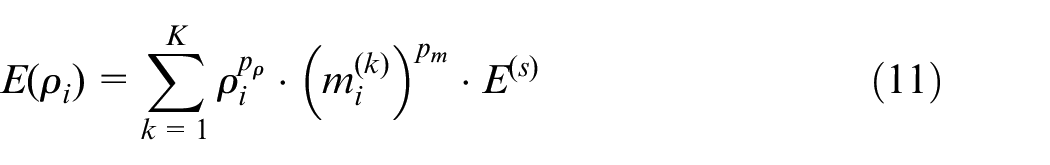
where
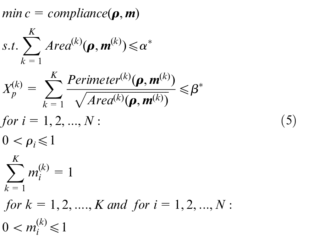
Thanks to the domain discretization and the relaxation of joint stiffness model mentioned above, the overall structural compliance can be defined as the optimization objective and in conclusion, the formulation of manufacturable casting parts design with topology optimization of structural assemblies is shown as follows.
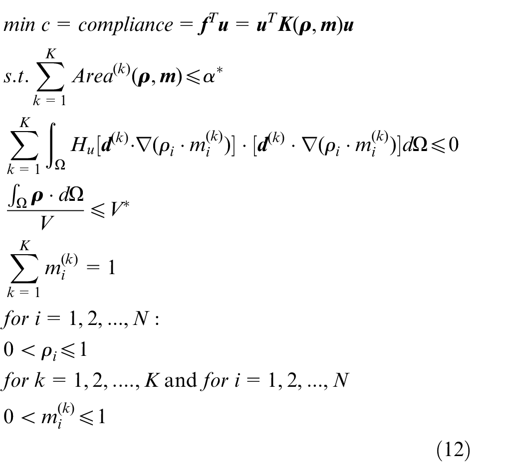
where
Numerical examples and discussion
In this section, some numerical examples are implemented to examine the validity of the proposed method. The four classic mechanical boundary conditions are illustrated in Figure 8. Since the topology optimization problem in equation (12) has multiple linear or nonlinear, equality or inequality constraints, the fmincon function with the interior-point method in the MATLAB software environment is applied. All derivatives of objectives and constraints are derived by MATLAB symbolic math toolbox and the Hessian is approximated numerically by finite difference method.
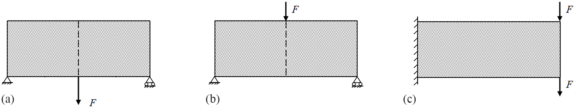
Design domain and boundary conditions: (a) bridge structure, (b) MBB beam, and (c) cantilever beam (upper or lower).
For all numerical examples in this paper, the ratio of the width of Type A joint elements to the length of structural elements is set as 0.2. For problems with finer mesh, this ratio can be set to larger values. The ratio of the Young’s modulus of joint elements to the one of structural elements are set as 0.7, reflecting a common situation of melt inert gas welding (MIG) or tungsten inert gas welding (TIG) which are two mainstream welding processes between casting parts.29–31 This value can be set differently based on users’ specific requirements. Considering some main situations for the joint elements, the power parameter
In order to ensure the convergence in the process of gradient-based optimization, the power parameter
Various boundary conditions
Some single-mold component numerical examples with 40 × 20 meshes for various boundary conditions are implemented and the prescribed number of components K is equal to 3. Element density
Figure 9 shows the topology optimization results with single-mold component and the overall optimized structure, component structures and undercut structure diagrams with relevant component baseline (from left to right) are all included, where the relative gray scale indicates the amount of undercut structure. Only few undercut structures (<8% elements in the overall structure) can be found on the component baseline. This is because the location of each structural element is related with its centroid and there will be some errors in determining whether they are involved in the undercut calculation which have no obvious negative effects in the aspect of convergence process or the optimized results. As for the undercut structures on the boundary of component, they occur as “the burrs” after filtering and the amount is small. Each component baseline (green line) is located at the boundary of each component and parallel to the main direction, and the drawing direction
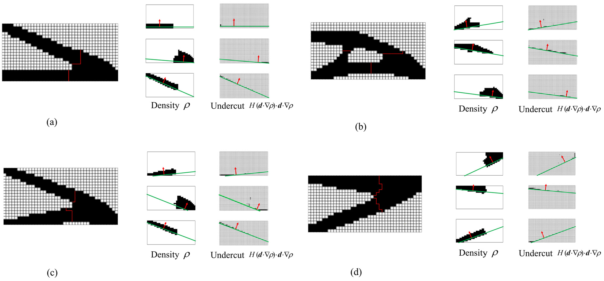
Optimization results for various boundary conditions: (a) MBB beam (undercut structure: 3.4%), (b) bridge structure (undercut structure: 5.7%), (c) cantilever beam (lower) (undercut structure: 7.4%), and (d) cantilever beam (upper) (undercut structure: 6.8%).
As there is only one drawing direction in each component for the single-mold parts design, the topology optimization results in Figure 9 show simple geometric shape. Figure 10 shows the comparison among single-mold, two-mold casting parts, and the stamping parts design in MTO-S. 14 Compared to single-mold casting parts, two-mold casting parts show more complex geometric shape as the multiple drawing directions. The multiple casting molds lead to an increase cost in mold manufacturing which exchanges for the improvement of structural performance. Figure 10(c) shows the design of stamping parts based on the theory in MTO-S. As the introduction of moldability constraint has controlled the generation of undercut structures and interior voids, there are no complex geometric contour and interior void inside components like stamping parts which is beneficial to improve the manufacturability of casting parts.
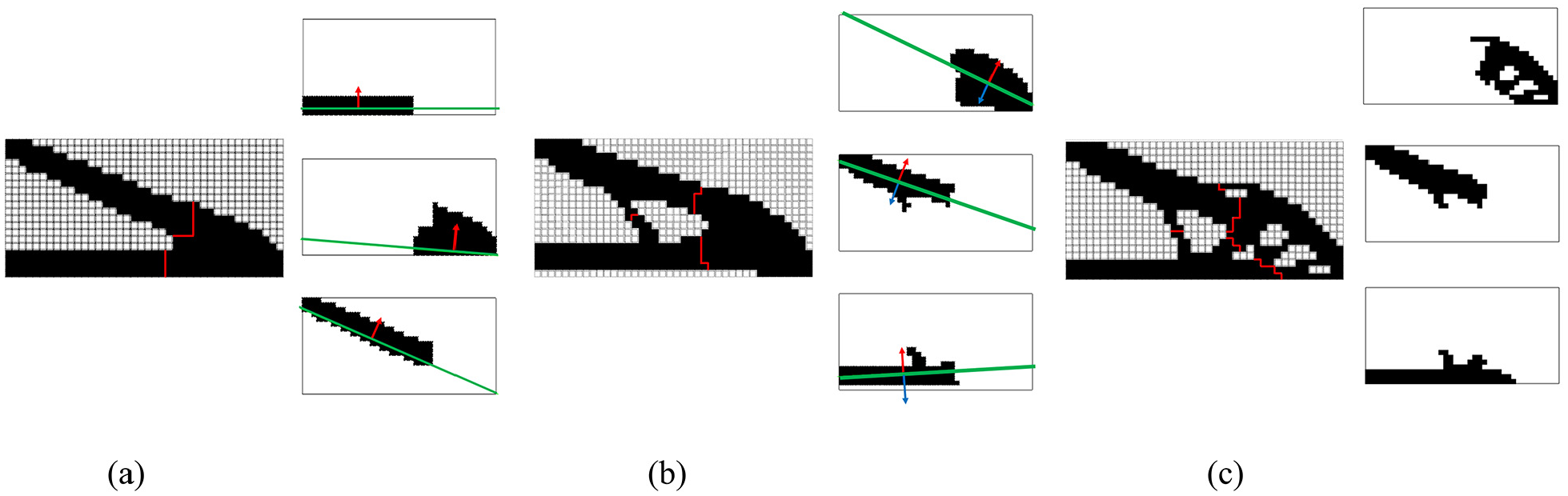
Optimization results of single-mold, two-mold casting parts, and stamping parts for MBB: (a) single-mold, c = 110.69,(b) two-mold, c = 101.77, and (c) stamping, c = 99.41.
MABB area constraint limit
Different MABB area constraint limits represent different requirements for the die-set material cost. In this section, different MABB area constraint limits
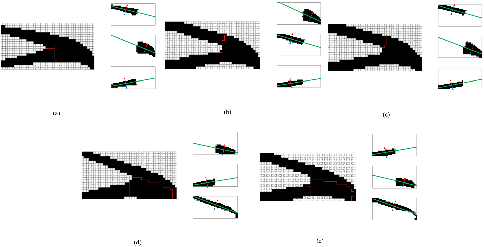
Topology optimization results with different MABB limit value: (a) α* = 3e8, c = 122.33; (b) α* = 4e8, c = 92.07;(c) α* = 5e8, c = 91.10; (d) α* = 6e8, c = 93.40; and (e) α* = 7e8, c = 94.96.
Number of components
In this section, the optimized results with various prescribed numbers of components K are shown in Figure 12 and the relationship among compliance, volume fraction, and the number of components K is presented by line chart. It can also be observed that a smaller number of components will result in a larger area of the sub-components which means that fewer elements will be reserved. Therefore, for two-component design, the design solution will have a lower volume fraction and a poorer structural performance; As the number of components increases, the required area of sub-components decreases, and more elements can be reserved. The volume fraction of design solution increases as well as structural performance; However, the positive effect is gradually reduced due to the limit of the volume constraint. At the same time, as the number of components increases, the amount of joint elements gradually increases. As the Young’s modulus of joint element is less than that of structural element, it can be predicted that if the number of components continues to increase, there is a risk that the structural performance of optimized solution will become worse (K = 5). Therefore, it is recommended that multiple runs should be conducted with different number of components and the final design solution can be chosen based on the practical situation.
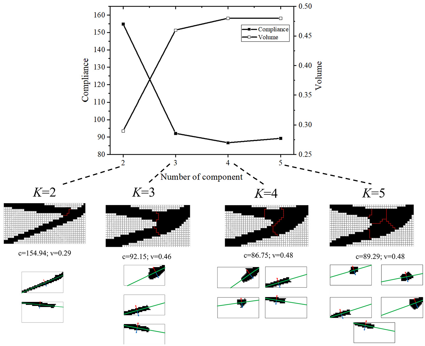
Topology optimization results with different number of components.
Discussion
Some numerical examples are implemented to examine the validity of the proposed method. By comparing all the numerical examples in Section 4, it can be observed that the overall structure can be divided into several components during the optimization process, and the number of undercut structures has also been effectively controlled. The optimized results in Figure 9 show that the proposed method is applicable for various boundary conditions and the moldability of each component has been improved with no more than 8% undercut structure. The introduction of component baseline can realize the design of single-mold castings, and it is also suitable for two-mold casting parts after being extended to the parting line in Section 4.2 and 4.3. Compared with single-mold design, the two-mold design has a better structural performance and manufacturability at the expense of increasing the number of molds. In Figures 11 and 12, it can be observed that the setting of MABB area constraint limits and the number of components will have a significant effect on the performance of the optimized structure. Due to the limitation of computing power, the domain, and boundary conditions are simple. With the improvement of computing power, the more complex boundary conditions will be considered in the next research stage. Users can achieve the desirable solution based on their actual demand by making trade-offs between the structural performance and manufacturing cost.
Conclusion
This paper presented a manufacturable casting parts design with topology optimization of structural assemblies which considers the geometry requirement constraint and die cost manufacturing constraint. The moldability constraint is modeled based on the vector method combined with Heaviside function. By introducing the component baseline function, the filtering of the base structure of component can be achieved. The component baseline can also be extended to the parting line to obtain the form of two-mold design. Simultaneously, the component baseline has a potential application in additive manufacturing process as there are base structures for building direction as well. Compared with other topology optimization methods in introduction, the method in this paper shows that a manufacturable design of casting parts with structural assemblies can be obtained and enables an efficient and effective manufacturing.
It is expected that the future research will consider castings parts made from multiple molds, the number of molds for casting parts can be selected flexibly in the optimization process, which will provide more freedom for optimization and better design solutions may be achieved potentially.
Footnotes
Declaration of conflicting interests
The author(s) declared no potential conflicts of interest with respect to the research, authorship, and/or publication of this article.
Funding
The author(s) disclosed receipt of the following financial support for the research, authorship, and/or publication of this article: This work was supported by the National Natural Science Foundation of China [grant numbers 51775228]; and the program of China Scholarship Council [grant numbers 201606170196].