
Abstract
In finishing machining, the quality of workpiece is significantly influenced by the performance of solid cutting tool. Solid cutting tool flank is ground by CNC tool grinder in accordance with the tool path of grinding wheel. In actual grinding process, the grinding area of wheel will be gradually worn down, resulting in the decrease of geometric accuracy of flank and even wrong profile. In order to compensate the error, a compensation algorithm of tool path for solid cutting tool flank based on grinding wheel wear is proposed. Firstly, the coordinate systems are defined for the grinding process of flank, and the orientation and location calculation model of ideal wheel with the grinding process parameters is derived. Secondly, based on the profile description of wheel wear, flank errors are analyzed. Then, the compensation algorithm for anastomosis of cutting edge and relief angle is proposed. Finally, series of experiments of simulation and actual grinding are carried out. The comparison of the results shows that the algorithm can reduce the influence of wheel wear effectively, which can also improve the grinding quality stability and prolong the service life of grinding wheel.
Introduction
Solid cutting tool is widely used in machining process which plays an important role in product quality. In finishing machining process, the quality of workpiece is significantly influenced by the performance of tool. Solid cutting tool is the most widely used for surface milling, groove milling, step face milling and copy milling. In recent years, many scholars have done a lot of research on solid cutting tool, such as surface quality, 1 geometric models, 2 and performance optimization. 3 As the key structure of the solid cutting tool, the flank (including the end teeth and the peripheral teeth) is responsible for reducing the machining friction force, ensuring the strength of the cutting edge, and determining the precision of the cutter profile size. Subsequently, the geometric shape of flank directly affects the performance of cutter.
The grinding process of solid cutting tool is very important for its precision and quality. The tool path calculation about grinding wheel position based on mathematical formulas of the cutting edge includes three location parameters and three orientation parameters of wheel. There are three evaluation indexes of the geometric shape of the flank, the edge width of flank, the relief angle and the anastomosis of side cutting edge. The edge width and relief angle are both defined under the normal section of the cutting edge. The anastomosis refers to the degree of coincidence between the cutting edges of flank and helical groove.
In the past few years, many scholars have carried on the derivation research around the mathematical model of flank. Han et al. 4 established the mathematical model of the cutting edge of flank with circular head and defined the grinding mode. Hsieh and Wang 5 derived the mathematical model of ball head milling cutter. In their research results, the mathematical models of the cutter cutting edge were established, and wheel positions relative to tool were both obtained.
As for helical groove of solid cutting tool, Kang et al. 6 utilized the principles of differential geometry and kinematics to formulate a generalized helical groove machining model through a CAD approach. Ehmann and Devries 7 established the mathematical relationships to facilitate the determination of the grinding wheel profile for a given radial drill flute cross-section. Xiao et al. 8 formulated a new mathematical model of the flute parameters in terms of the dimensions and the set-up angle of the 4Y1 wheel. Karpuschewski et al. 9 presented an automatic method of searching for a wheel location in flute grinding for a given shape of the helical flute and wheel profile which is based on the main loop and two subroutines. Li et al. 10 introduced an intelligent method to search for the optimum wheel location for the designed groove with the known wheel geometry and built a robust algorithm to predict machined grooves with a series of equal distribution points. Hsieh 11 established a mathematical model of the helical groove and conducted a sensitivity analysis for helical groove machining performed on a 6-axis tool-grinding machine. Ren et al. 12 derived the equations for calculating the flute parameters and created a system of nonlinear equations to calculate the wheel location for flute grinding, using standard 1V1/1A1 wheels to ensure the accuracy of the three flute parameters. Their research results in helix groove have laid a solid foundation for the research on flank, especially in the anastomosis of the two cutting edges.
In the aspect of wheel shape detection, the detection methods are also various and constantly optimized. Dimla 13 presented a review of some of the methods that have been employed in tool condition monitoring, which can be extended to wheel wear monitoring. In direct way, vision system and an optical microscope are used to directly detect the contour of wheel.14–16 Su proposed a method for measuring wheel contours using machine vision, simplifying wheel wear measuring procedures compared with the traditional methods. 15 Jurkovic et al. 16 determined the wheel profile directly with the help of projected laser raster lines. Dutta et al. 17 analyzed digital image processing in the respect of monitoring tool and wheel. In indirect way, the features of the collected physical quantities, such as vibration 18 and surface roughness, 19 are used to evaluate the wheel wear. Xu et al. 18 compared the energy ratio extracted from vibration signal with the wheel wear status evaluated by experiment, and applied the further extracted features to the prediction of wheel wear status. Dutta et al. 19 calculated the wheel wear condition by collecting the processed surface image in real time and analyzing the collected image. Lei et al. 20 presented a Randomized Hough transform to detect circles from a digital image which reduces the storage requirement and the computing time. Guo et al. 21 introduced an intelligent wheel wear monitoring system which is capable of predicting wheel wear more accurately even with less features. What’s more, Prasad and Ramamoorthy 22 predicted tool wear by artificial neural network. In terms of compensation research, Xu et al. 23 proposed a virtual grinding point method based on process features, and the experimental results showed that the spherical surface grinding precision was significantly improved. Liu et al. 24 determined the wheel contact conditions based on the iterative algorithm for groove grinding compensation research. For smooth surface grinding track, Xu et al. 14 compensated grinding error by comparing wear arc radius of wheel with contour curve radius of workpiece.
However, the researches on precision machining of flank have some deficiencies.
Many researches mainly focus on the grinding model of flank without considering wheel wear.4,5
The profile of grinding wheel wear is simplified as an arc in order to simplify the research process, which will lead to inaccurate compensation.14,24
Not enough attention has been paid for the compensation of relief angle, which causes inaccurate edge width of flank.
In order to solve those problems, a compensation algorithm of tool path for solid cutting tool flank based on grinding wheel wear is proposed. It has three steps:
A mathematical model of the cutting edge and a theoretical tool path of corresponding grinding model based on ideal wheel are derived.
Based on the profile description of wheel wear, the actual grinding area is detected, and the flank errors are analyzed.
The relative compensation of tool path for anastomosis of cutting edge and relief angle is calculated.
The paper is organized as follows: By defining different coordinate system and introducing wheel lifting angle, the theoretical mathematical model of location and orientation of ideal wheel is derived in Section 2. Section 3 analyzes the grinding errors caused by wheel wear, and the actual profile of wheel is descripted. Then the errors for the anastomosis of the cutting edge and relief angle are compensated. To validate the proposed algorithm, a series of experiments are carried out in Section 4. Finally, some conclusions are drawn in Section 5.
The theoretical tool path of ideal grinding wheel
The definition of coordinate systems
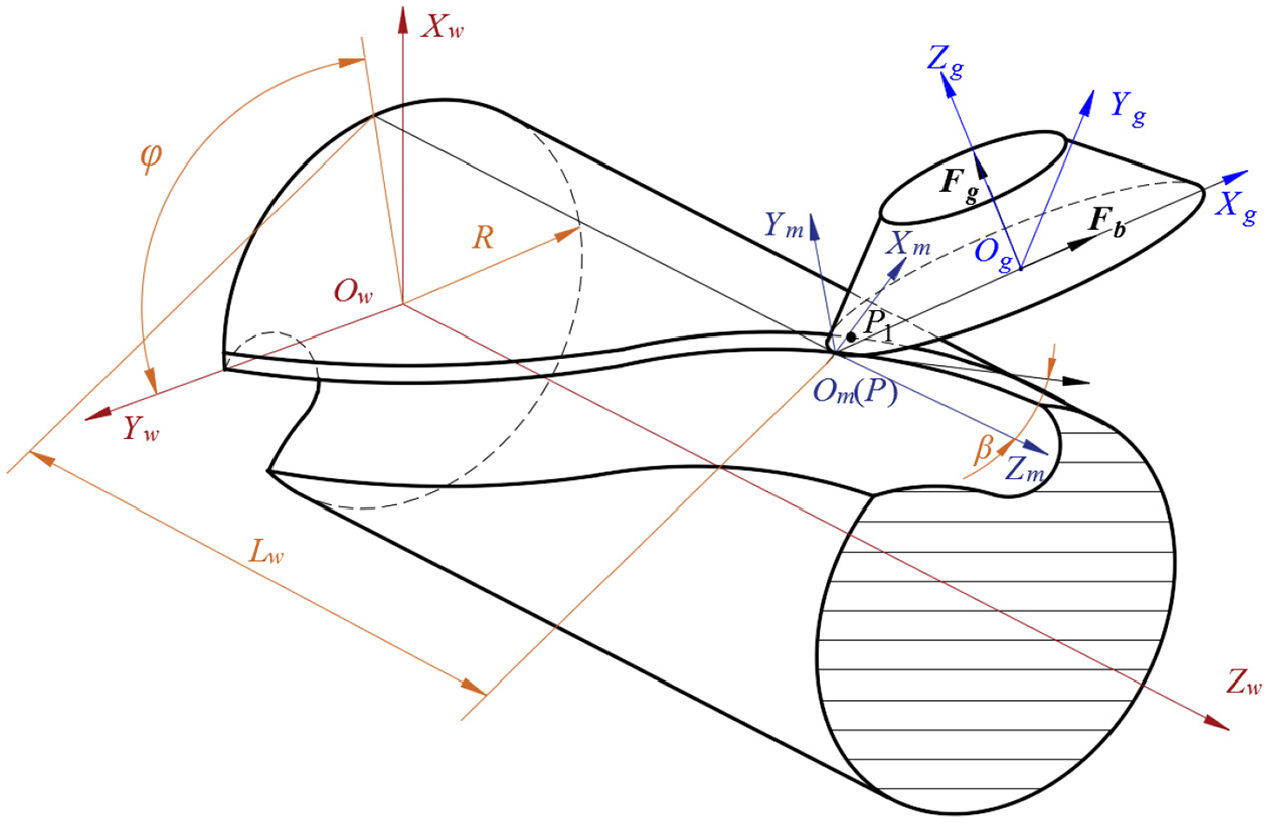
Without loss of generality, the flank of an end mill is given to illustrate the calculation method of ideal wheel position. As shown in Figure 1, WCS is defined as workpiece coordinate system, origin Ow as the center of the cutter bottom, axis Zw as the cutter axis, and axis Yw as the vector from origin Ow to the starting point of the cutting edge. The wheel position relative to the cutter needs to be described in this coordinate system. Set one point on the cutting edge as grinding point P, which is also the point on the wheel profile of maximum diameter. Define R as the radius of the cutter, Lw as the axial distance between point P and cutter bottom.
The definition of coordinate systems.
To describe the characteristics of flank accurately, define the movable coordinate system of cutting edge as MCS, origin Om as the point P, the direction of axis Zm as axis Zw, axis Ym as the normal vector of the external profile of cutter, φ as the angle between axes Yw and Ym, point P1 as the intersection of coordinate plane YmXm and the second cutting edge, and R as the cutter radius.
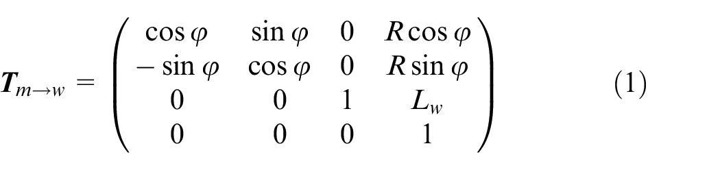
where
and β is the constant helical angle between the tangent vector of the cutting edge at that point and the tool axis. 25
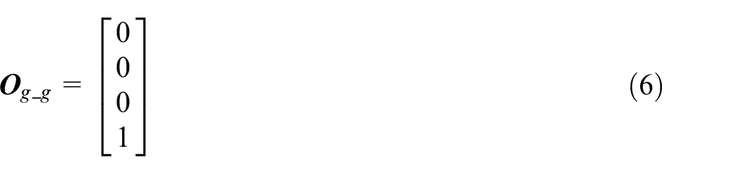
To describe the characteristics of wheel accurately, define the grinding wheel coordinate system as GCS to describe profile shape of wheel, origin Og as the center of the front face of wheel, axis Xg as the vector from point P to origin Og, axis Zg as the axis of wheel,
The initial position of grinding wheel
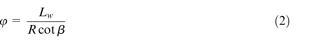
As shown in Figure 2, in the coordinate plane YmXm, define vector
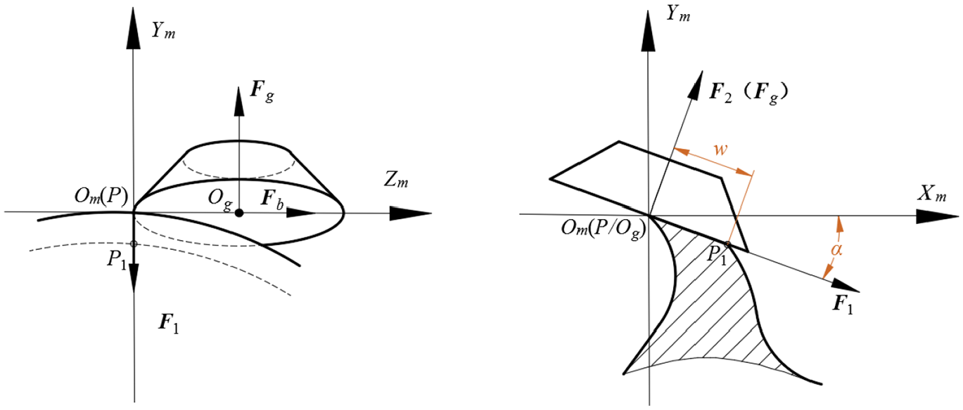
The definition of initial wheel position.
According to the spatial geometric relationship, the initial wheel position can be expressed in the MCS by equations (3) and (4) with subscript _ m expressed in the MCS.


where Rg is the maximum diameter of the ideal wheel.
The position of grinding wheel with lifting angle
To avoid grinding interference and reduce grinding contact area, it is necessary to rotate the wheel around vector
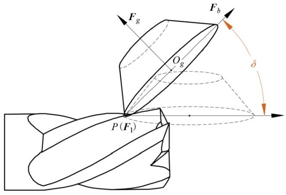
The wheel position with lifting angle.
In order to obtain the coordinate of point Og after rotating δ around vector
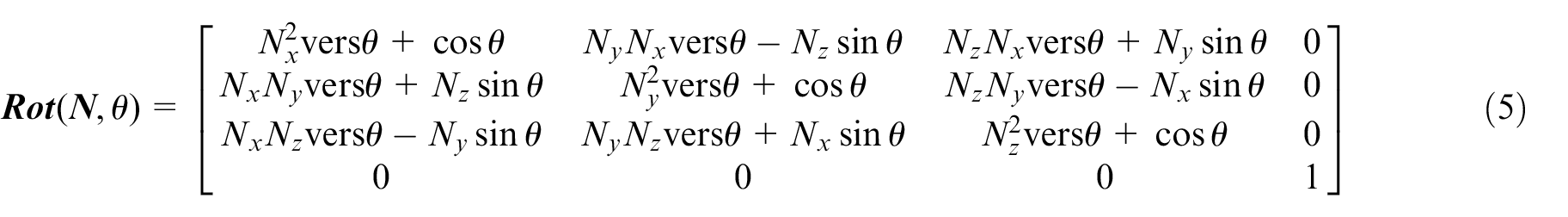
where vers θ=1-cosθ.
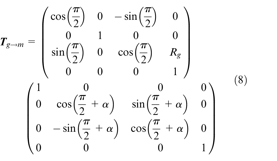
With lifting angle δ, the coordinates

where
The tool path compensated with grinding wheel wear
The profile description of grinding wheel wear
Tapped straight type (1V1) or bowl type (11V9) grinding wheels are usually applied to grinding flank, of which the grinding areas and conditions are similar. In actual machining, the wheel will be gradually worn out with the accumulation of grinding time. As shown in Figure 4, R′g is defined as the maximum diameter of worn wheel. If the tool path of grinding wheel is calculated according to R′g, the grinding point of the wheel will be converted from point P to point P’. So flank will have some errors about edge width, relief angle and anastomosis of cutting edge.
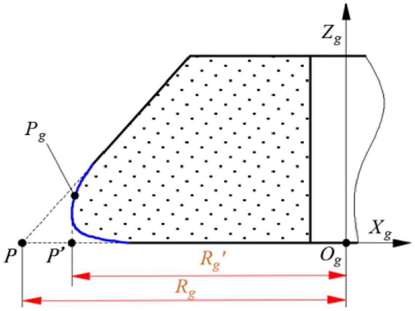
The cross-section of a worn wheel.
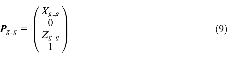
The actual profile of worn wheel can be described by a series of points Pg through some wheel profile measurement methods and instruments, which can be expressed in GCS by equation (9).
The compensation for anastomosis of cutting edge
To compensate for the worn wheel, relief angle coordinate system (RCS) is established based on MCS. RCS is obtained by rotating MCS around axis Zm with angle α, as shown in Figure 5.
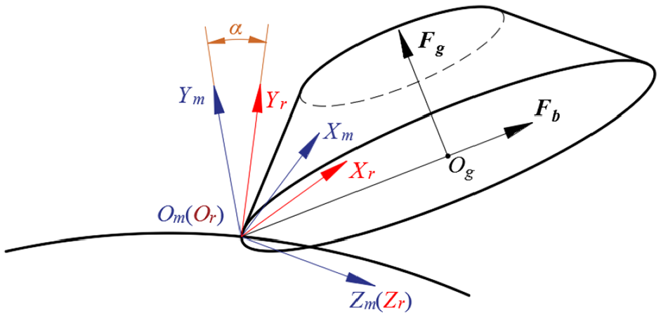
The definition of RCS.
So the rotation matrix
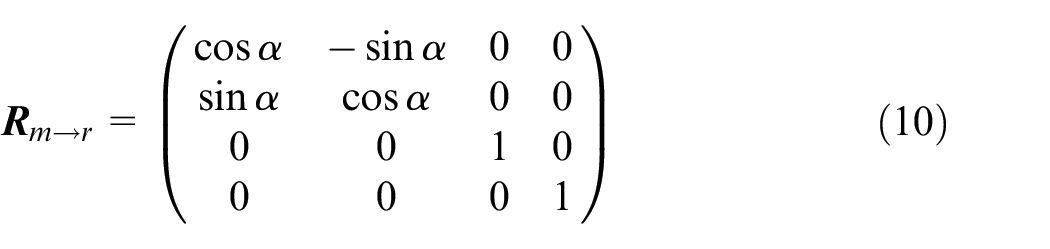
In RCS, vector
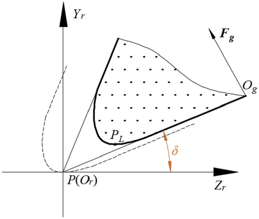
The compensation for the anastomosis of the cutting edge.
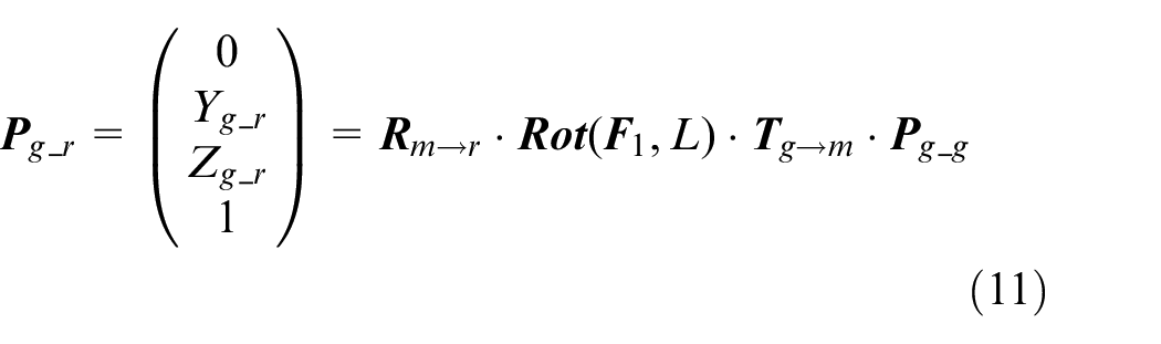
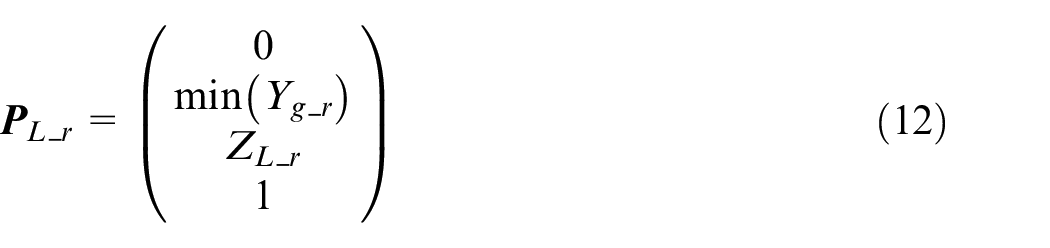
According to the above derivation, for the anastomosis of cutting edge, the wheel should be moved from point PL to point P without changing the wheel orientation, as shown in Figure 6.
The compensation matrix in RCS is defined as
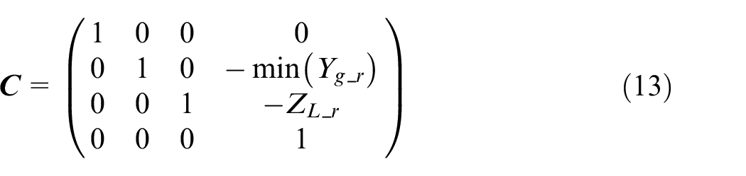
With compensation, initial origin

The compensation for relief angle
According to the different lifting angles, the grinding process for flank can be divided into two types: plane type and concave type.
In this paper, the two special lifting angles values of 0° and 90° are analyzed in detail. As shown in Figure 7, the angle between vector
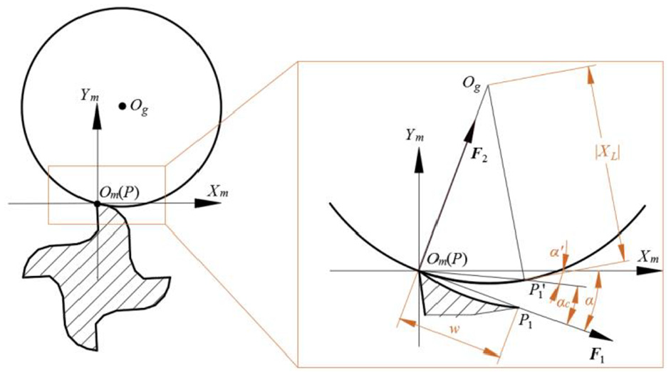
The grinding posture when lifting angle is 90°.
According to spatial geometry, compensation angle αc for the relief angle with different lifting angles can be calculated approximately by equation (15).
where xL_g is the coordinate of point PL in GCS.
If the second or third flank needs to be machined, its compensation method is similar to that of the first flank. The compensation algorithm of anastomosis of cutting edge and relief angle has certain universality, which can be extended to the grinding process for flank of straight edge and chamfer edge.
Experiment
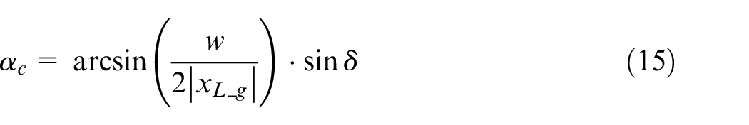
In this paper, flank of spiral edge about one solid cutting tool with a diameter of 10 mm was identified as the verification object. One 11V9 type worn grinding wheel, the grinding ratio (the volume of material of cemented carbide removed divided by the volume of SDC wheel wear) 27 ranges from 80 to 120, with an ideal diameter of 100 mm was selected, as shown in Figure 8.
The worn 11V9 grinding wheel for verification.
The precise contour of the worn grinding wheel was obtained by grinding the soft material with the wheel on the five-axis CNC tool grinding machine, as shown in Figure 9. And the Cutting Tool Inspection Systems PG1000 was used to detect the grinding wheel contour, as shown in Figure 10. The intersection point of the outer profile of the grinding wheel is taken as the basis point to get the wheel profile coordinates in GCS, as shown in Figure 11.
The grinding for the precise profile of the worn grinding wheel.
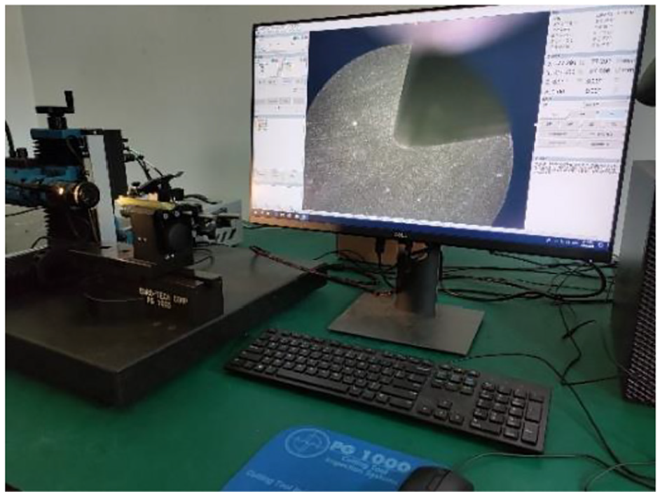
Cutting Tool Inspection Systems PG1000.
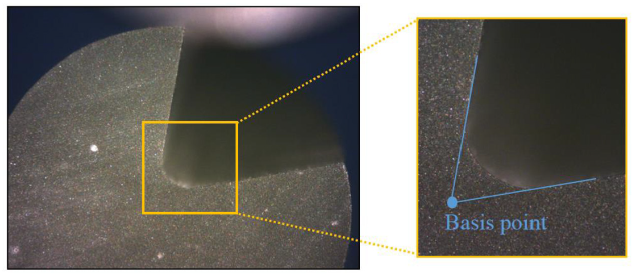
Profile of the worn grinding wheel.
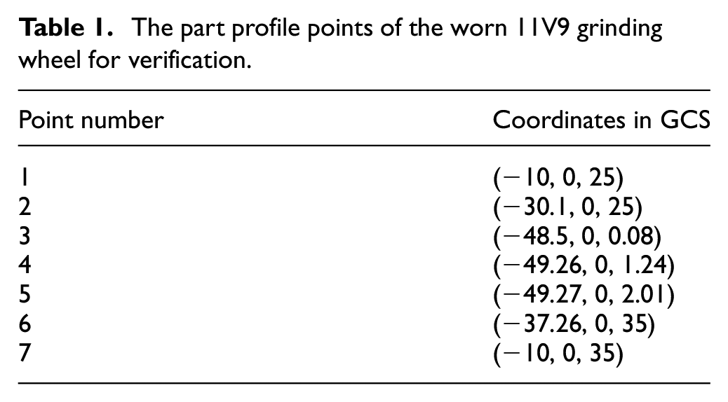
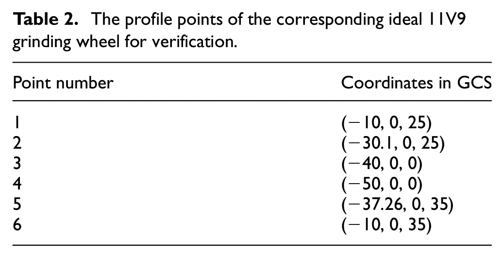
The part profile points of the wheel are listed in Table 1, and the profile points of the corresponding ideal grinding wheel are also listed in Table 2.
The part profile points of the worn 11V9 grinding wheel for verification.
The profile points of the corresponding ideal 11V9 grinding wheel for verification.
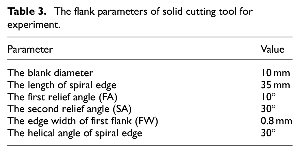
The main structural parameters of flank are shown in Table 3.
The flank parameters of solid cutting tool for experiment.
The experiment of simulation grinding
Grinding simulation with lifting angle equaling to 45° was carried out in software VERICUT 8.0. The grinding wheel models are shown in Figure 12, where (a) is the worn grinding wheel model of the actual processing, and (b) is the corresponding ideal grinding wheel model.
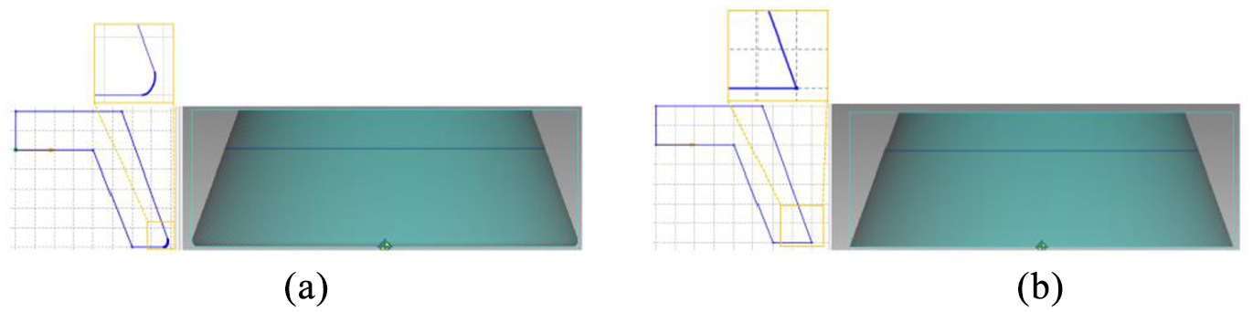
The model of the worn and ideal grinding wheel: (a) the model of worn grinding wheel and (b) the model of ideal grinding wheel.
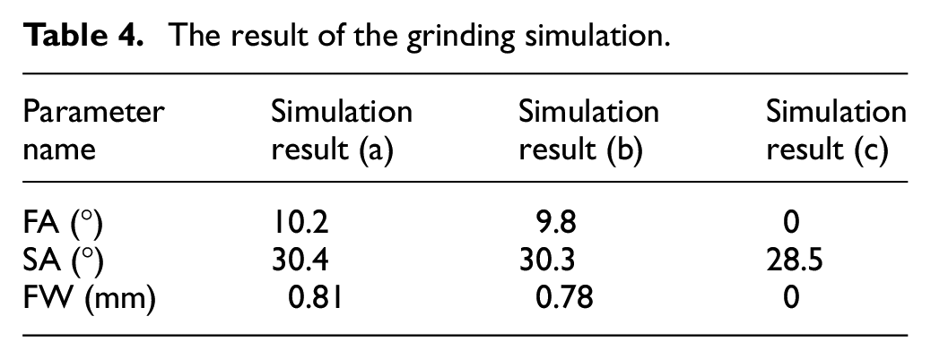
The simulation results in cutter cross-section are shown in Figure 13, where the result (a) is ground by the ideal grinding wheel with theoretical tool path, the result (b) is ground by the worn grinding wheel with compensated tool path, and the result (c) is ground by the worn grinding wheel with theoretical tool path. The results of the simulations are shown in Table 4. Comparing the results (a), (b) and (c), the machining result with compensation meet the design requirements, and the precision of relief angle and edge width is well improved.
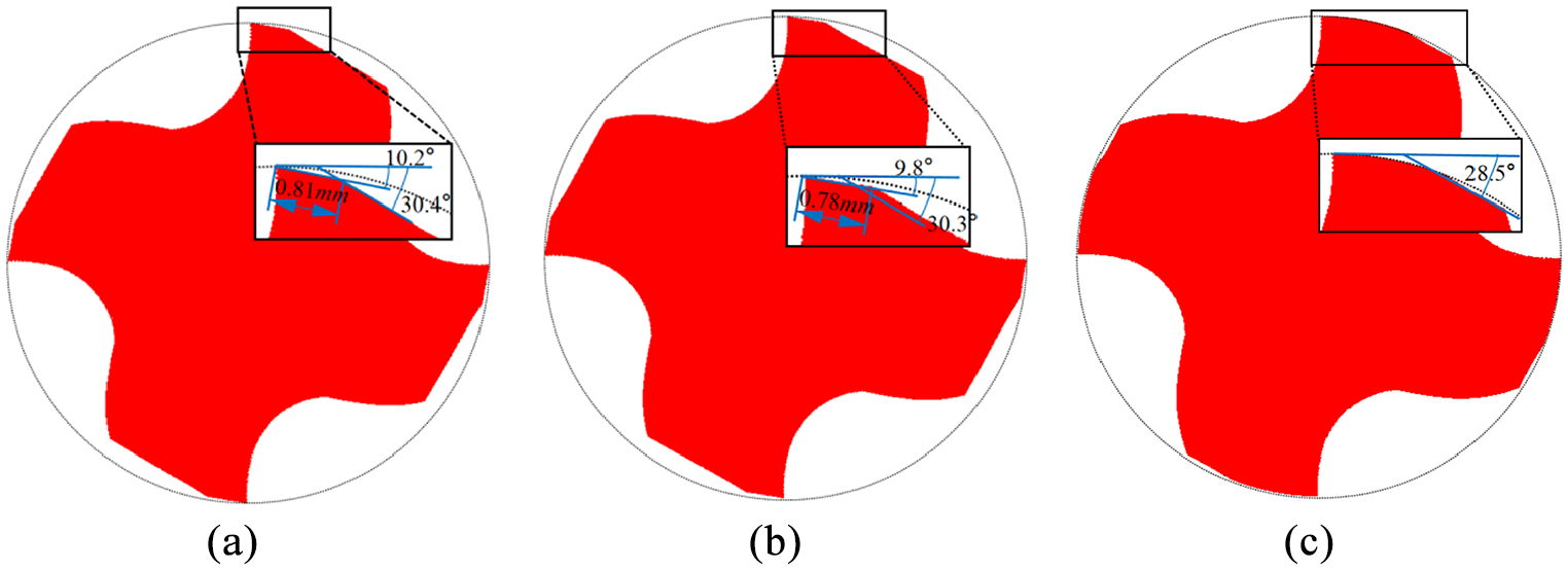
The simulation results of the flank grinding in cross-section: (a) the result of ideal grinding wheel with theoretical tool path, (b) the result of worn grinding wheel with compensated tool path, and (c) the result of worn grinding wheel with theoretical tool path.
The result of the grinding simulation.
The experiment of actual grinding
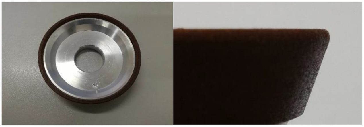
A five-axis CNC tool grinding machine was applied in actual grinding verification, as shown in Figure 14.
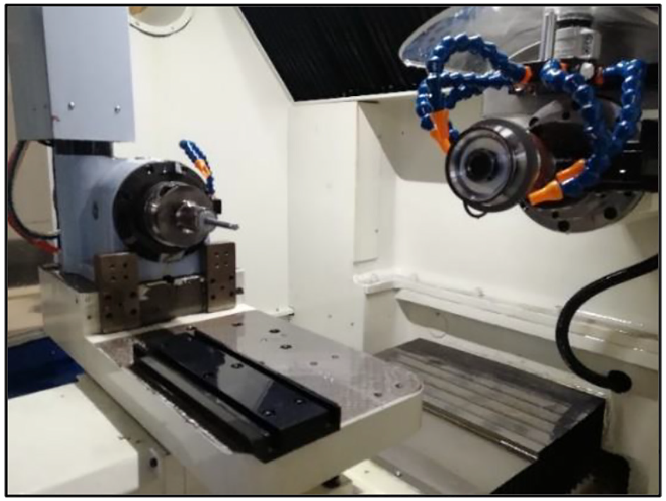
The five-axis CNC tool grinding machine for verification.
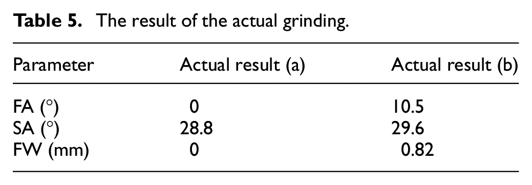
Figure 15 depicts the cross-section results of actual grinded tools. The result (a) is ground by the worn grinding wheel with theoretical tool path, and the result (b) is ground with compensated tool path. The parameter results of the profiles detected by PG1000 are shown in Table 5. The actual grinding results are consistent with the simulation ones, which indicate the grinding algorithm improves the machining precision remarkably.
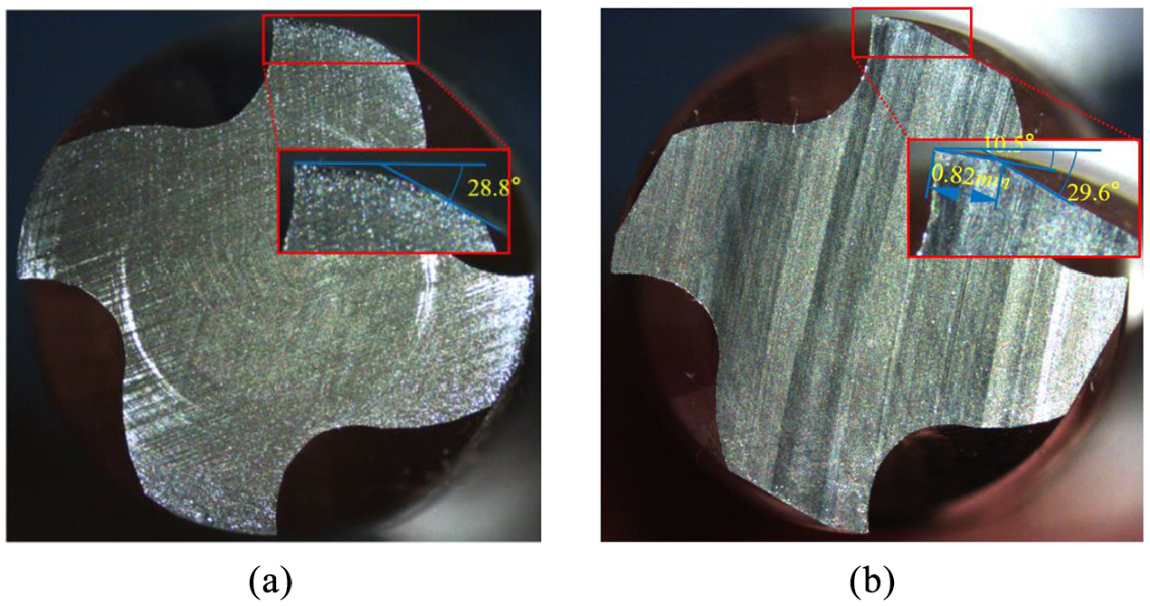
The actual results of the flank grinding in cross-section: (a) the result of worn grinding wheel with theoretical tool path and (b) the result of worn grinding wheel with compensated tool path.
The result of the actual grinding.
To validate the grinding precision of proposed algorithm further, a set of workpieces are ground. Figure 16 depicts the relationship between the lifting angle in grinding process and relief angle, edge width of flank. When the lifting angle is from 0° to 10°, the first relief angle (FA) has a large error. When the lifting angle is from 0° to 15°, the errors of the second relief angle (SA) and the edge width of the first flank (FW) are also obvious. When the lifting angle is between 15° and 90°, the geometric profile of the flank meets the design requirements. The main reason for the errors is that the grinding interference will occur when the lifting angle is between 0° and 15°. Figure 17 depicts the cross-section results of grinding with different lifting angles. The result (a) shows that the material in the lower right corner of the cross-section is incorrectly removed when the lifting angle is 8°, which will directly affect the machining accuracy of other teeth. On the contrary, as shown in result (b), when the lifting angle is 35°, the material in the lower right corner of the cross-section is not removed, so the machining accuracy of the other teeth can be ensured. Therefore, it is recommended to set the lifting angle between 20° and 90° in actual grinding process.
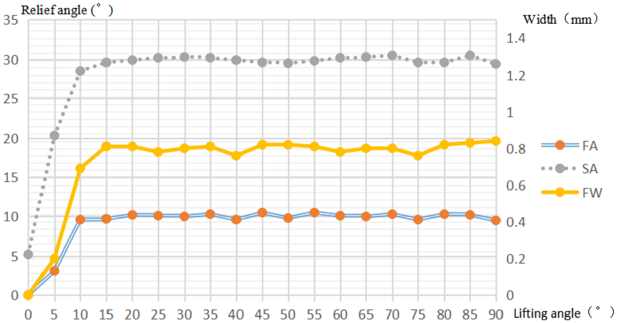
The effect of lifting angle on flank.
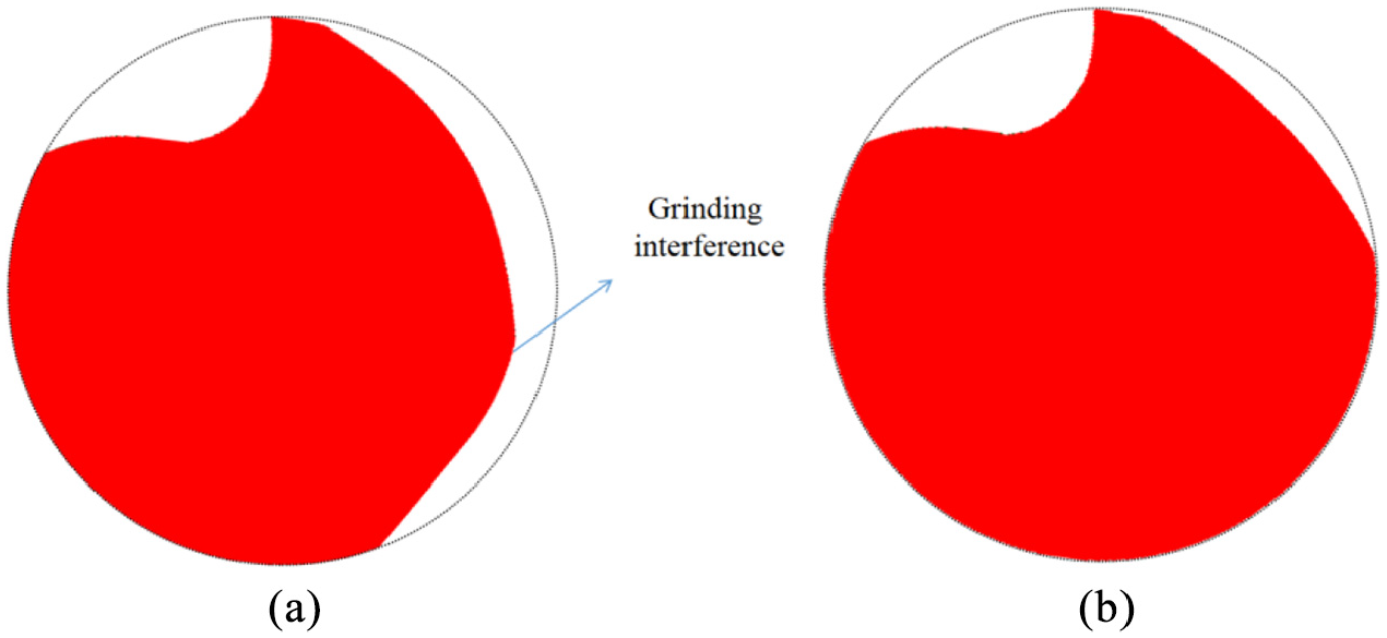
Cross-section results of flank face grinding with different lifting angles: (a) the result of lifting angle equaling to 8° and (b) the result of lifting angle equaling to 35°.
Conclusions
This paper presents a compensation algorithm of grinding solid cutting tool flank with a worn wheel. Within the paper, a mathematical model of the cutting edge and the theoretical tool path of corresponding grinding mode based on ideal wheel are derived. Based on the profile description of worn wheel, the relative compensation of tool path for anastomosis of cutting edge and relief angle is calculated. The method is implemented by using C++ and validated by a set of tests. The test results show that the cutting edge and relief angle tolerances are controlled within 6.2%. With the proposed compensation algorithm, it can make the flank face meet the design requirements by using a worn wheel, which can improve the grinding quality stability and prolong the service life of grinding wheel.
Footnotes
Declaration of conflicting interests
The author(s) declared no potential conflicts of interest with respect to the research, authorship, and/or publication of this article.
Funding
The author(s) disclosed receipt of the following financial support for the research, authorship, and/or publication of this article: This work is supported by the Science and Technology Plan Project of Sichuan, China (2020YFG0122).