
Abstract
Due to good aerodynamic performance and reliability, countersunk bolt joint is one of the most commonly used connection methods for carbon fiber reinforced polymer (CFRP) components in the aircraft. However, the countersunk hole machining process is inevitably accompanied by geometric errors, which will directly affect the mechanical properties of the joint structure. This paper presents a numerical and experimental investigation on the effect of countersunk hole geometry errors on the fatigue performance of CFRP bolted joints. FE model of CFRP countersunk bolted joints with designed geometry errors are established, and the rationality of the FE analysis was verified by fatigue life and failure forms. The CFRP bolted structure failure mechanism under fatigue load and influence of hole-making geometry error (including countersunk fillets radius, countersunk depth, and countersunk angle) on the fatigue life are investigated. Based on the relationship between fatigue life and the geometry error, the corresponding tolerances for CFRP bolt joint countersunk hole are determined as well. The research results can provide a reference for establishing reasonable geometric accuracy requirements for CFRP joint hole machining.
Introduction
In the aerospace manufacturing industry, the usage of carbon fiber reinforced polymer (CFRP) has increased rapidly due to their excellent mechanical properties, 1 and the corresponding structural components joining is essential for aircraft construction. Because of the accessibility, low cost and easy disassembly, mechanical fastening is widely used during the aircraft assemble process. In the current mechanical fasten methods, countersunk bolted joint is one of the most common methods of joining CFRP structures, particularly for skin-structure due to its high aerodynamic efficiency,2,3 such as fuselage, tail, nose, and wing skins of aircraft. However, these mechanical joints are inevitably accompanied by detrimental effects, such as increased structural weight and lower fatigue performance. Poorly designed or installed joints are not only an inducement for joint failure, but could lead to a reduction of the durability and reliability of the aircraft structure. 4 Therefore, the mechanical performance of countersunk CFRP bolted joints has attracted lots of attentions recently.
Many experimental investigations on bolted joints of composite laminates have been conducted to clarify the effect of bolting parameters on its mechanical behavior. Chishti et al. 5 investigated the effect of bolt torque, clearance and countersink height ratio on the damage progression and joint strength limit. In order to assess the failure behavior of bolted joints for composite laminates and investigate potential strain rate effects on it, series of experimental tests were carried out by Heimbs et al., 6 it was concluded that no rate sensitivity occurred for most test configurations. Nixon-Pearson and Hallett 7 carried out an extensive experimental to investigate and understand the sequence of damage development throughout the life of bolted-hole composite laminates under quasi-static loading and tension-tension fatigue under bolt washer pressures of 23 and 70 MPa. Saleem et al. 8 investigated the influence of two different drilling processes on the mechanical behavior of bolted composite joints by using fatigue tests combined with infrared thermography. It was demonstrated that machined surface quality of CFRP joint hole is an important factor for the fatigue life of corresponding bolted composite joints. Recently, Nezhad et al. 1 studied the progression of damage in CFRP countersunk composite bolted joints under quasi-static loading for both single and three bolt styles. It was found that the ultimate failure point corresponds to the composite piles undergoing intra-laminar damage with the size reaching to the edge of the countersunk head.
In addition to the experimental methods, numerical simulation is another commonly used approach for CFRP bolted joints’ mechanical behavior analysis. Based on a detailed finite element investigation of composite bolted joints with countersunk fasteners, the correlation between the joint stiffness and the contact status between bolts and holes were presented. 9 In order to obtain better simulation accuracy, a continuous degradation model in the three-dimensional finite element model of composite bolted joints was applied by Hühne et al., and the influence of liquid shim layers on the structural behavior of composite joints was investigated by using this approach. 10 For the countersunk composite joints, Egan et al. 11 investigated the mechanical behavior of single-lap composite joints secured with finger-tight countersunk fasteners in detail and revealed the influence of bolt-hole clearance on the mechanical performance. However, the delamination process was treated as matrix crack between two plies in the above numerical simulation model. In order to address this problem, two new explicit models were established and proposed a time-saving and accurate simulation method to predict the in-plane ply failure of single-lap bolted joint between composite laminate and steel with countersunk fastener in Liu et al. 12 Recently, Cao et al. 13 developed a progressive damage model to investigate the effects of clearance and interference sizes on the failure of CFRP/Ti double joint. Numerical results showed that the matrix compression failure dominated the joint failure mode. For the influence of tightening torque magnitudes on the fatigue behavior of single-lap bolted laminates, Feyzi et al. 14 proposed a three-dimensional FE model with progressive damage model to assess damage and failure in the bolted joints.
Through the above mentioned experimental and numerical simulation methods, a more comprehensive analysis for the mechanical properties or service performance of the composite joints has been carried out. However, because the joint performance of composite bolted components is significantly affected by hole-making quality and geometric errors, the CFRP machinability and machining quality have drawn great attentions.15–20 For the hole-making process, Fernández-Pérez et al. 21 investigated the influence of cutting parameters on tool wear and hole quality during the CFRP drilling process. Ahmadi and Zeinedini 22 elaborated the drilling effects on delamination of laminated composite material by combining experimental, theoretical and numerical methods. In addition to the machined surface quality, the geometric and dimensional accuracy of the machined hole are also important factors for the joint structure service performance. For the helical milling hole-making process, Amini et al. 23 investigated the effects of process parameters like cutting velocity and feed rate on the hole geometric accuracy. It was concluded that increasing cutting velocity can improve the accuracy of hole diameter, circularity and cylindricity in the CFRP helical milling hole-making process. To achieve the better geometric accuracy, Zhang et al. 24 investigated the tool center point vibration on the machined surface quality of UD-CFRP under different fiber orientations, including surface waviness, 3D surface roughness, and depth of affected zone. It was found that the fiber orientation and milling style are two important factors that affect robot vibration and machining quality during the CFRP trimming. From above literature review, it can be noted that the machining damages in CFRP machining can be reduced or eliminated by optimizing the machining conditions, while geometric accuracy errors are inevitable.
The stress generated on the joint is significantly affected by the hole-bolt geometries. Improper geometry would lead to serious stress concentration and poor joint strength. And Liu et al. presented the numerical and experimental investigation on the effect of countersinking depth and angle of machined hole on the tensile strength of the single-bolted countersunk joint. 25 It was concluded that the countersinking depth has a significant influence on the tensile strength of the composite joint, which should be strictly controlled in the hole-making process. Recently, Tian et al. 26 investigated the effect of countersunk hole depths on the tensile-tensile fatigue behavior of the riveted aluminum alloy. It can be found that larger countersunk depth will result in a fatigue life reduction for the aluminum rivet structure. However, from the literature review, the effects of machining geometry error of CFRP countersunk on the bolted joint’s fatigue life was not investigated in detail. It is inevitable that there will be geometric errors in the countersunk hole-making process. In this paper, the effects of countersunk geometries error, including countersunk fillet radius (R), countersunk angle (θ), and countersink depth (H) (As shown in Figure 1) on the fatigue performance of single-lap and single-bolt CFRP joints were studied by combining finite element modeling and experimental method. The results are helpful for establishing the relationship between the accuracy of CFRP hole-making and the fatigue behavior of the joints structure.
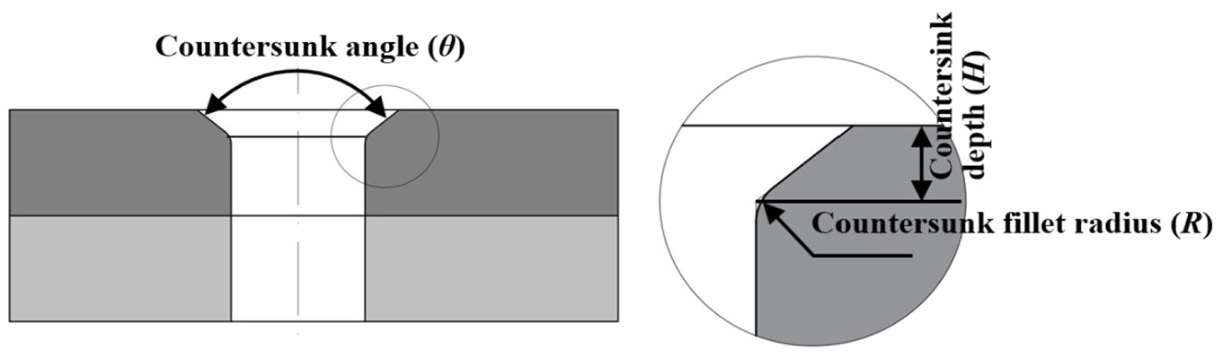
The main factors for countersunk hole geometry errors: countersunk fillet radius (R), countersunk angle (θ) and countersunk depth (H).
Finite element modeling of CFRP countersunk bolted joints
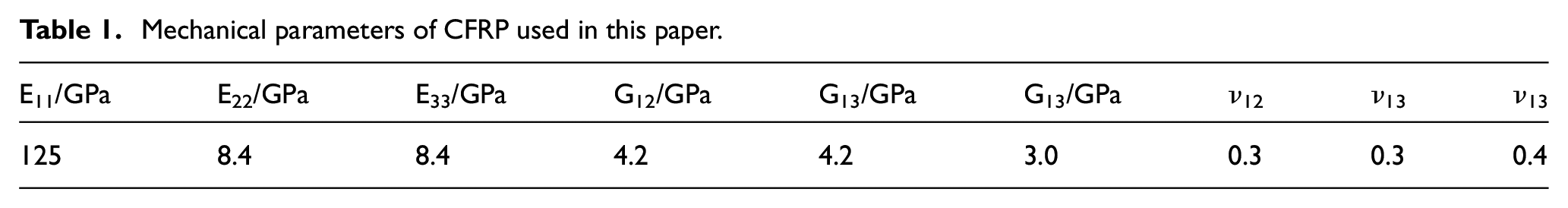
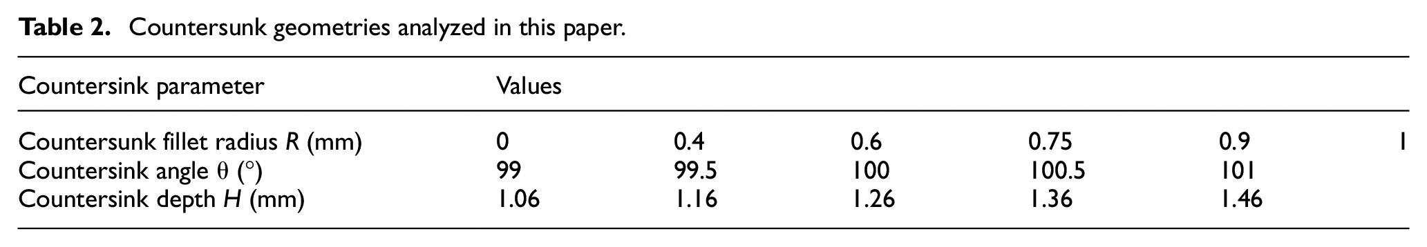
Compared with the 2D finite element model, the 3D finite element model can obtain more accurate simulation results for the deformation of the CFRP laminate and the stress distribution around the joint area, such as delamination and out-of-plane bucking, as well as stacking sequence effects and secondary moment in the area close to the bolt. Therefore, in this paper, the 3D FE models of the single-bolt, single lap, countersunk CFRP joints were developed in the commercial software ABAQUS/Explicit. The dimensions of the specimens are determined based on the ASTM-D5961 27 and paper, 28 as shown in Figure 2. The CFRP laminates were made of T700/epoxy and consisted of 40 plies with a quasi-isotropic (QI) stacking sequence [−45/90/45/0/90]4s. The 100° countersunk-head fasteners are made of Ti6Al4V (E = 115 GPa, ν = 0.342), and the material of the nut is AL7075 (E = 71.7 GPa, ν = 0.33). The relevant dimensions of countersunk head bolt, such as depth of the countersunk-head, diameter, and countersunk angle, are shown in Figure 2. The above mentioned materials’ mechanical parameters are shown in Table 1. Sixteen numerical models with different countersunk fillet radius (R), countersink angle (θ), and countersink depth (H) (Table 2) are constructed to predict the corresponding fatigue performance of CFRP bolted joints.
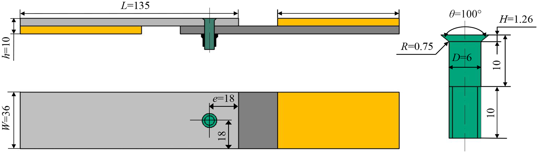
Geometrical configuration of bolted joint specimen (all dimensions in mm).
Mechanical parameters of CFRP used in this paper.
Countersunk geometries analyzed in this paper.
According to the structure of the multi-directional CFRP material used in this study, the corresponding FE model of CFRP laminate consisted of 40 layers and the same stack sequence with test specimens was arranged. In this numerical model (Figure 3), the CFRP laminate was meshed with C3D8R continuum 3D hexahedral elements, and in order to obtain better simulation results, the adaptive mesh refinement was conducted in the meshing process near the bolt hole. It results in 60,673 nodes and 53,188 elements. The progressive damage model which involves the stress analysis, material degradation, and failure analysis was performed. The 3D Hashin failure criteria were employed in this study to predict the damage formation of CFRP material. Meanwhile, both sudden material property degradation and gradual material property degradation were considered under cyclic loading condition. The material degradation criterion used in this paper are shown in the paper. 29
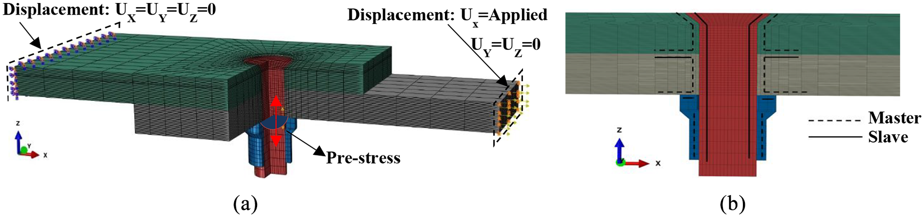
FE mode of the CFRP bolted joint: (a) boundary conditions and (b) contact condition definition in the FEM.
The boundary conditions were also presented in Figure 3(a). The displacements of one side of the test piece were all defined as zero, and a horizontal external load (in X direction) was applied to the other end. In order to obtain the pre-stressing of bolt, five twist-off tests of nuts were carried out on a torsion lacerating machine shown in Figure 4. The pre-stressing of the bolt for five twist-off tests are 7.749, 8.855, 8.754, 8.146, and 7.992 kN, and the average value is 8.299 kN. So an 8.299 KN pre-stressing force was applied to the shank of the bolt. The friction between top and bottom CFRP laminates was set as 0.32 and friction between CFRP and metal (bolt) were 0.16, and the penalty friction model was used to solve the converge problem in other models. Contact conditions were applied by defining contact pairs between interacting surfaces. Slave surfaces were defined, which were unable to penetrate their corresponding master surface. The surface-to-surface discretization method was employed, which can prevent surface penetration in an average sense and can provide a more accurate simulation result than the node-to-surface discretization method. The master and slave assignments are shown in Figure 3(b).
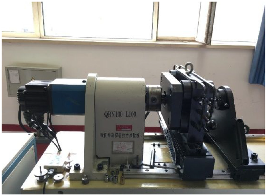
Twist-off tests of nuts set-up.
Test verification
In order to verify the proposed numerical model and investigate the effect of the countersunk geometry errors on the joint fatigue performance, sixteen specimens with different countersink geometry sizes (as presented in Table 2) were prepared. As shown in Figure 5, the DMU-80T five-axis machining center and specially designed machining tools for hole making and countersinking were used to ensure the precision of the machined hole. Meanwhile, due to the smaller cutting force and better quality, helical milling hole-making process was applied to generate the straight holes before drilling the countersunk hole. In order to ensure the actual machined hole dimensions were consistent with the experimental design, all the machined holes were measured by the coordinate measuring machine, and the specimens that did not meet the requirements were removed.
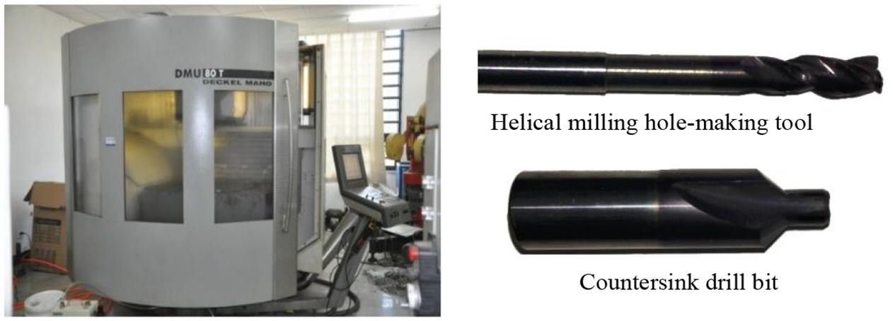
Machining equipment and hole-making tools.
Before the fatigue test, the static tensile tests were carried out on a 300 kN electronic tensile testing machine to obtain the ultimate strength of the joint, and then to determine the appropriate load for the fatigue tests. The displacement control method was applied in the static test, and the corresponding loading rate was 2 mm/min. When the specimen reached the maximum strength, the loading is continued for a certain period of time and then stopped, and the load-displacement curve and failure mode of the specimen are recorded. In the static tests, the geometric dimension of countersunk-hole was fixed as R = 0.75 mm, θ = 100°, and H = 1.26 mm. The static tensile tests were repeated four times, and the tensile load-displacement curves were obtained, as shown in Figure 6. The significant deformation and delamination can be observed when the tensile load reached its tensile limit, and then the fracture occurred in the CFRP laminated. The corresponding ultimate tensile force for four tensile tests are 14.33, 15.06, 15.59, and, 13.27 kN, and the average value is 14.563 kN. Therefore, the fatigue load in this paper was set as 10 kN, loading frequency was 10 Hz, and stress ratio was 0.1.
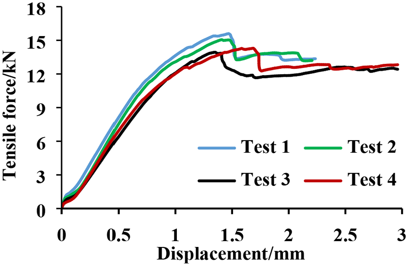
Load-extension behavior of the CFRP countersunk bolted joints.
In this paper, the fatigue performance tests are conducted on a 50 kN electro-hydraulic servo fatigue testing machine (Instron 8802). It is considered that the joint reaches the failure criterion when the joint hole diameter increases by 10%. 27 However, it’s difficult to measure hole diameter directly during the fatigue tests, so, the joint elongation was measured to evaluate the increase of hole diameter. An Instron 2260-601 electronic extensometer was used to record the joint elongation and displacement in real-time. The fatigue test set-up was shown in Figure 7. Meanwhile, ultra-depth microscopy and ultrasonic C-scan were used to observe and analyze the failure in the joint area. As shown in Figure 8, the ultrasonic C-scan results of top and bottom CFRP plate after fatigue tests were presented. It can be seen from the figure that the fatigue damages are mainly distributed in the load direction, and the upper countersink showed more serious damage than the bottom hole.
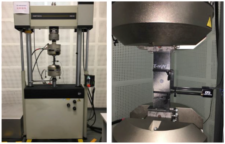
Fatigue test set-up.
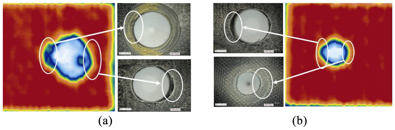
Fractured CFRP specimens and ultrasonic scan results after fatigue test: (a) top and (b) bottom CFRP plate.
Results and discussion
Fatigue failure analysis of sample
In the fatigue test, the joint displacement fluctuated up and down depending on the change of the fatigue load. Figure 9(a) shows the change of maximum and minimum displacements for each cycle with increasing fatigue load cycles. The difference between the maximum and minimum displacement can reflect the stiffness of the specimen. The larger displacement difference, the smaller elastic stiffness for the connection structure. The entire fatigue failure process can be divided into three stages by the speed of displacement variation. The damages of the CFRP bolted joint corresponding to each stage are shown in Figure 9(b) to (d). From the observation results, it can be seen that in the first and second stage of fatigue loading, there is no obvious material damage, but the connection holes of the bottom CFRP plate have some distortion in the tensile direction. For stage 3, serious compression failures for both the top and bottom CFRP joint holes were appeared, and the displacement increased rapidly.
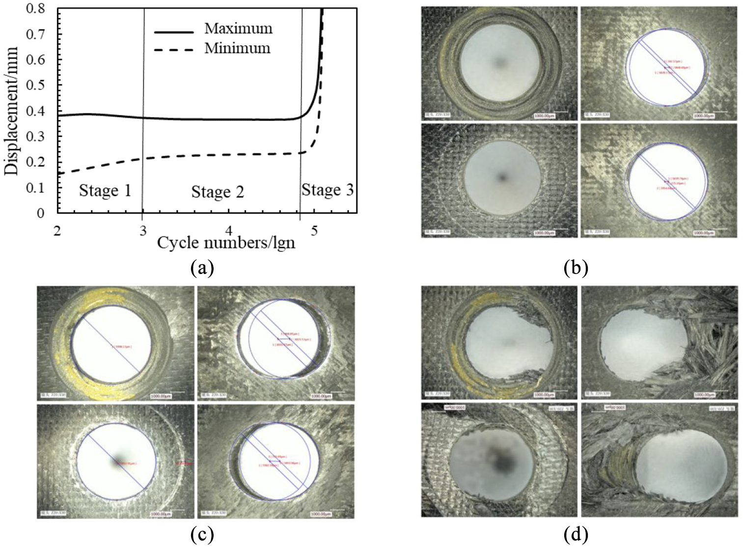
(a) Relationship between the displacement and fatigue cycle number, and the fatigue damage of joint holes at different loading cycles, (b) stage 1, (c) stage 2, and (d) stage 3.
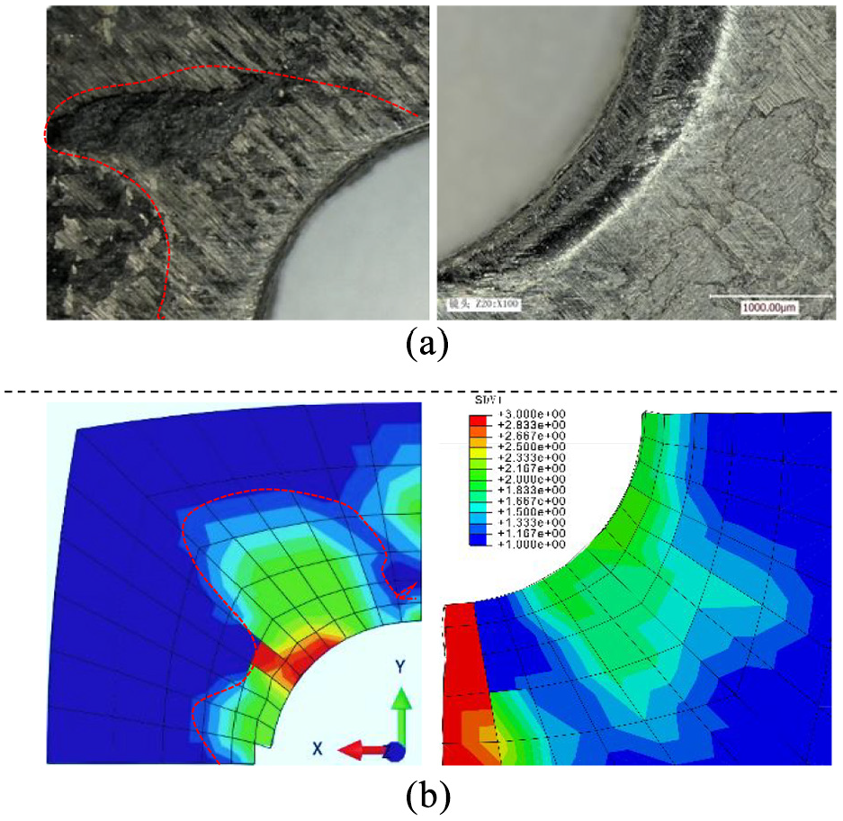
The common forms of fatigue damage in CFRP laminate include fiber fracture, matrix delamination, fiber-matrix debonding, and so on. 30 The stress distribution around the CFRP countersunk hole is quite complicated, and the failure modes are usually a combination of various damage forms. From the experimental observations and numerical simulation results, two different forms of material failure can be found both in the contact surface between the top and bottom CFRP plates and the wall of the joint hole. First, due to the friction effect between two specimens during the fatigue loading, the obvious wear damage can be found in the contact surface of CFRP specimens around the bolt hole, as shown in Figure 10(a). It was noticed that the closer to the edge of hole, the more severe wear damage. The corresponding simulation results are shown in Figure 10(b), which are in good agreement with the experimental observations. The experimental and simulation results of fatigue damages for bolted hole wall are shown in Figure 11. From the figure, it can be seen that the main damages are mainly found at the exit of the top bolted hole (marked as region A) and the entrance of the lower bolted hole (marked as region B), which are caused by the crushing action of the bolts. Meanwhile, the damage of the lower specimen is more serious than that of the top CFRP specimen, and this is consistent with the simulation results, which greater stress can be found in the lower CFRP specimen.
Wear damage in the contact area around bolt hole: (a) experiment observation and (b) simulation results (R = 0.75 mm, H = 1.26 mm, θ = 100°).
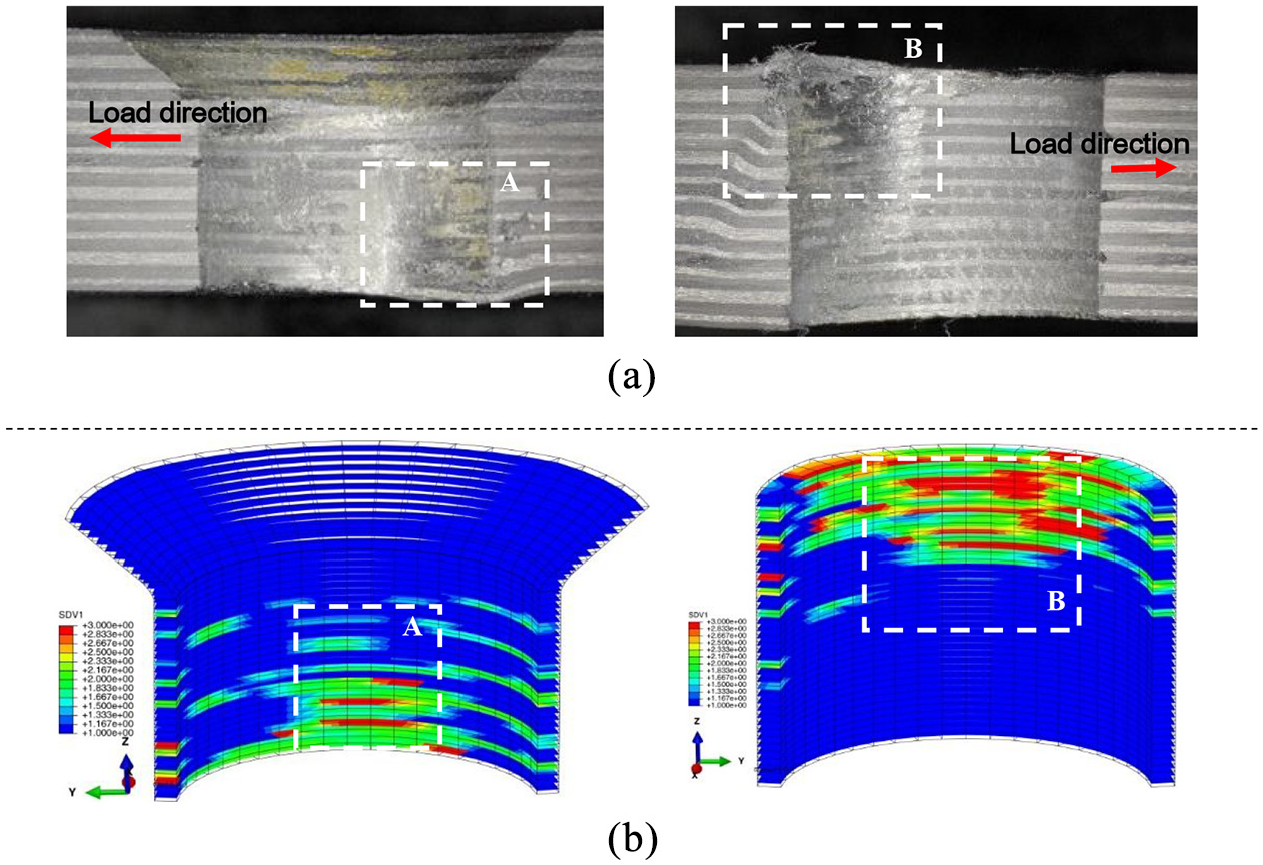
Fatigue damages in the bolted hole wall: (a) experiment observation and (b) simulation results (R = 0.75 mm, H = 1.26 mm, θ = 100°).
In order to investigate the effects of countersunk hole geometry errors on the fatigue performance, the von Mises stress distribution and damage distribution around the hole for different countersunk fillet radius, depth, and angle were obtained, as shown in Figure 12. From the simulation results, it can be found that the variation in geometry parameter of joint hole will lead to the differences in the stress magnitude as well as the stress distribution. Meanwhile, based on the maximum stress in the top and bottom CFRP plate for different hole geometry errors, it was indicated that the top and bottom plates are not equally sensitive to stress fluctuations. From the comparison between Figure 12(a) to (c), it was presented that the countersunk fillet radius has a greater effect on the stress in the bottom plate of CFRP bolted joint, while the countersunk depth and countersunk angle have a greater effect on the stress in the top CFRP plate.
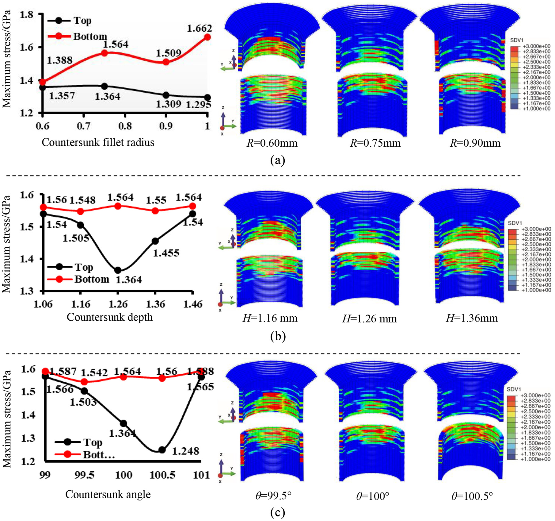
Variation of maximum mises stress and damage distribution of joint holes under different geometry condition: (a) countersunk fillet radius (R = 0.60 mm, R = 0.75 mm, R = 0.90 mm), (b) countersunk depth (H = 1.16 mm, H = 1.26 mm, H = 1.36 mm), and (c) countersunk angle (θ = 99.5°, θ = 100°, θ = 100.5°).
Effect of geometry errors on fatigue performance
In this paper, sixteen cases with different countersink fillet radius (R), countersink angle (θ), and countersink depth (H), as shown in Table 2, were analyzed by finite element analysis (FEA). The simulation results were shown in Figure 13(a) to (c). As illustrated in the figure, when the number of fatigue loading cycles is lower than 1 × 10⁴, the displacement of specimen basically remains the same; when the number of fatigue loading cycles is between 1 × 10⁴ and 5 × 10⁴, the displacement appears to increase slowly; and when the number of cycles exceeds 5 × 10⁴, the displacement will increase rapidly until fatigue failure occurs. Meanwhile, the experimental tests with three different countersink fillet radius, countersink angle, and depth were conducted as well, and the correlations between the number of fatigue cycles and the displacement with different fillet radius, countersink depth, and countersink angle were shown in Figure 13(d) to (f). Compared with the experimental results, although the process from damage generation to final failure is slower, the final fatigue life obtained by simulation is agreed with experimental results.
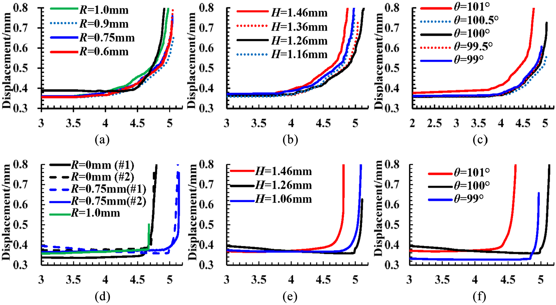
Relationship between the displacement and fatigue cycle number under different fillet radius: (a–c) results of FEA, and (d–f) results of fatigue test.
From the above results, the final fatigue life for different R, H, and θ can be obtained when displacement reachs 0.6 mm (10% of joint hole diameter). In order to clearly show the hole geometry errors affecting the fatigue life of composite bolted joint, the parameter F is proposed as follows:
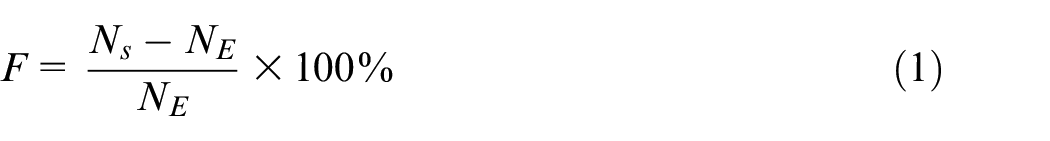
where the parameters Ns indicates the fatigue life of bolted joint under standard fit (R = 0.75 mm, θ = 100°, H = 1.26 mm), and NE represents the fatigue life of bolted joint with hole geometry errors. The parameter F can be used to estimate the influence of geometry error of the countersink hole on the fatigue life, which the positive value represents a decreased fatigue life, and the negative value represents an increased fatigue life.
The influence of countersunk hole geometry errors on the fatigue life are shown in Figure 14. It can be obtained that the difference between experimental and simulation results of fatigue life is approximately 16.5%–25%, and the variations between cycle number with displacement for FEA and experiment are quite close. As presented by Figure 14(a), the maximum fatigue life of the composite bolted joint is achieved when the countersink fillet radius is 0.9 mm. Besides, when the fillet radius is over 0.9 mm, the fatigue life of bolted joint has a rapid decrease. Furthermore, based on the relationship between fillet radius and fatigue life, the countersunk hole’s fillet radius tolerance could be determined with certain value of F. For example, if the fatigue life acceptance is designed higher than 95%, that is, F ≤ 5%, then the countersunk fillet radius should be in the range of 0.53–0.93 mm. As shown in Figure 14(b), there are about 10.0%–19.2% errors between the FEA and test results for different countersunk depth errors. However, both methods reached their maximum fatigue life of the composite joint when H = 1.26 mm, and they all have the same trend of decreasing fatigue life with increasing countersunk depth error. Meanwhile, as mentioned above, with 95% acceptance of F, the countersunk depth for composite bolted joint should be controlled in the range of 1.19–1.35 mm based on the simulation results shown in the figure. For the influence of countersunk angle on the fatigue life, the FEA and experimental results are shown in Figure 14(c), and the corresponding simulation error is about 10.2%–16.8%. Based on the fitted curve of the simulation results, in order to meet the requirement of fatigue life of composite bolted joint (F ≤ 5%), the countersink angle should be in the range of 99.8° and 100.6°. Meanwhile, from the above analysis results, it can be seen that the influence of positive and negative deviations of hole-making geometry on the fatigue performance of the CFRP bolted joint is not symmetrical, for example, the countersunk fillet radius and countersunk angle in this paper. Therefore, the tolerance of machining error range for the CFRP joint hole needs to be determined according to the actual influence of each geometric parameter on the mechanical properties of the joint structure.
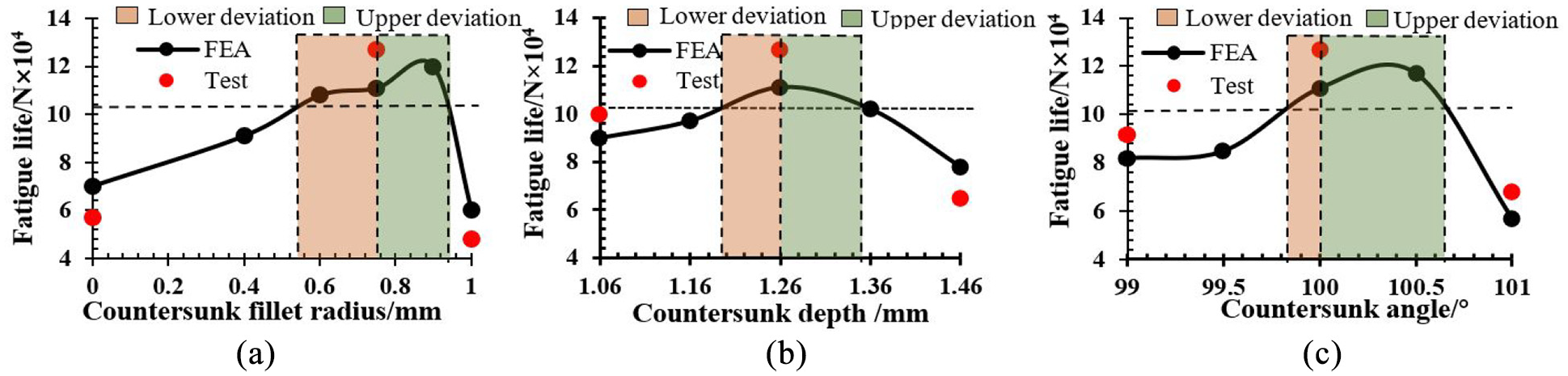
Comparison of fatigue life between FEA and fatigue test under different geometry conditions: (a) countersunk fillet radius/mm, (b) countersunk depth/mm, and (c) countersunk angle/°.
Conclusions
This paper presents a numerical and experimental investigation about the effect of countersunk hole geometry errors on the fatigue performance of CFRP bolted joints. FE model of CFRP countersunk bolted joints with designed geometry errors are established, and the rationality of the FE analysis was verified by fatigue life and failure forms. From the experimental observations and numerical simulation results, it can be found that wear damage and compression failure are the two most common forms for the CFRP bolted joint under tensile fatigue loading conditions. For the influence of geometry parameter of the joint hole, it was presented that the countersunk fillet radius has a greater influence on the stress in the bottom plate of CFRP bolted joint, while the countersunk depth and countersunk angle have a greater effect on the stress in the top CFRP plate. Meanwhile, it can be seen that the influence of upper and lower deviations of countersunk-hole on the fatigue performance of the CFRP bolted joint is not symmetrical. Based on the relationship between fatigue life and the geometry error, the corresponding tolerances for CFRP bolt joint countersunk hole can be determined to obtain better fatigue performance.
In addition to geometry errors, the effect of surface quality and delamination damage on the mechanical properties of the joint structure needs to be further analyzed in our future work.
Footnotes
Declaration of conflicting interests
The author(s) declared no potential conflicts of interest with respect to the research, authorship, and/or publication of this article.
Funding
The author(s) disclosed receipt of the following financial support for the research, authorship, and/or publication of this article: This work was supported by National key research and development program of China (grant number: 2017YFE0111300) and National Natural Science Foundation of China (grant numbers: 51705358, and 51775373), and Natural Science Foundation of Tianjin (grant number: 19JCYBJC19000).