
Abstract
Machining quality and productivity of superalloys are limited due to their poor machinability, and fewer studies have focused on the cutting of iron-based superalloys. In this study, the cutting performance of coated and uncoated carbide tools in high-speed dry turning iron-based superalloy GH2132 was investigated by performing a series of cutting experiments. The experimental results indicated that cutting temperature and cutting forces increased, while tool life decreased with the increase in the cutting speed from 30 to 100 m/min. Under relatively low cutting speeds, flank face wear was dominated by abrasion and adhesion, while rake face wear mainly involved built-up edge (BUE), built-up layer (BUL), adhesion, and breakage near the depth of cut. Under higher cutting speed, adhesion wear was more serious on the flank face, and peeling off of the coatings and substrate occurred on the rake face. Owing to the protective effect of (Ti, Al)N + TiN coating, the coated tools exhibited better wear resistance and thus longer tool life, in particular, under higher cutting speeds. Analysis of the tool wear gap in the horizontal direction indicates that better dimensional accuracy could be obtained when coated tools are used. In dry turning of GH2132 with carbide tools, a favorable surface finish could be obtained. The surface roughness roughly showed a tendency to first decrease and then increase with the increase in average flank wear. The coated tools should be avoided to machine GH2132 at higher cutting speed due to the poor surface finish.
Introduction
High-temperature alloys have been widely applied to aerospace and nuclear industries attributed to their excellent mechanical properties under extreme environments including elevated temperature, gas corrosion, and complex stress.1–3 Among them, the GH2132 superalloy, which is equivalent to A286, is a type of age hardened iron-based superalloy with good plasticity and excellent welding performance. 4 Owing to its good thermal strength and stability when being operated at temperatures below 650°C, it offers a broad range of application prospects as potential candidate for some high temperature components such as engine cases, turbine wheels, and blades. 5 Moreover, it can partially replace more expensive nickel-based superalloys in some areas where the operating temperature is relatively low. 6
However, high-temperature alloys belong to the category of difficult-to-cut materials on account of their low thermal conductivity and severe work hardening effect, which leads to elevated cutting temperature and large cutting forces. The machining efficiency gets limited due to their allowed lower cutting speeds. Although significant research attention has been paid to the machining of superalloys, the studies mainly concentrated on the nickel-based alloys such as Inconel 718.7–14 For instance, Rakesh and Datta 7 studied the tool wear mechanisms during dry cutting of Inconel 718 with uncoated carbide tools, and found that abrasion, adhesion, built-up edge (BUE), grooving, chipping off and chip welding, and burning were the main causes for tool failure. Anthony et al. 8 concentrated on the tool life issues during machining Inconel 718 using physical vapor deposition (PVD) (Ti, Al)N coated carbide, Al2O3–TiC ceramic and cubic boron nitride (CBN) tools, respectively. They found that tool wear was mainly influenced by thermal softening, adhesion, notching, diffusion, and thermal cracking. Compared to ceramic and carbide tools, the wear of the CBN tools was more serious. Thakur and Gangopadhyay 9 performed dry turning experiments of nickel-based superalloy Incoloy 825 with PVD multilayer TiN + (Ti, Al)N coated tools under conventional flood cooling and minimum quantity lubrication (MQL). The investigations showed that the cutting forces of TiN + (Ti, Al)N coated tools under dry machining was lower than that under conventional flood cooling and MQL. In order to investigate the surface roughness of Inconel 718 under dry cutting, Hua and Liu 10 performed dry turning tests under three different cutting speeds and feed rates using two cutting tools with different nose radii. They indicated that the cutting speed slightly affected surface roughness and the feed rate and tool nose radius were the dominant factors influencing surface roughness.
In contrast, only a few studies have been reported on cutting iron-based superalloy. Musavi et al. 15 conducted turning experiments of A286 by various cooling-lubrication methods including dry, wet, MQL, and minimum quantity cooling-lubrication (MQCL). In respect of reducing machined surface roughness and flank wear, MQCL is the most effective method. Wang et al. 16 investigated wear mechanisms of Al2O3-based ceramic tools in high-speed dry cutting of GH2132 and concluded that the major wear mechanisms were abrasive and adhesive wear. Furthermore, Tian et al. 6 applied Si3N4-based ceramic tool to intermittently cut GH2132, and found that the tool with graded structure showed superior thermal and mechanical shock resistance. Noteworthy, comparative analysis of coated and uncoated carbide tools in cutting iron-based superalloys, in particular, at high cutting speeds has still been rarely studied.
Nowadays, as people sustain to show concern for the environmental protection and energy consumption, the dry machining process has gradually become a new trend in manufacturing technique.15,17–20 For dry condition, higher requirements of wear and high-temperature resistance of cutting tools have been presented. Currently, cemented carbide tools are widely used and their coatings have been transformed from monolayer into multilayer due to extensive development in coating technology. Chen et al. 21 and Kulkarni and Sargade 22 investigated and compared mechanical properties of TiN + (Ti, Al)N multilayer and (Ti, Al)N monolayer coatings by different test methods. The experimental results showed that multilayer coatings were more superior. Therefore, it is a good try to use TiN + (Ti, Al)N coating carbide tools to machine iron-based superalloys.
In this study, cutting performance of cemented carbide and (Ti, Al)N + TiN multilayer coated carbide tools in dry turning of iron-based superalloy GH2132 was systematically studied. The cutting temperature, cutting forces and tool life were recorded. The tool failure morphology and mechanisms were analyzed and the machined surface roughness was studied as well. The results of this study offer an important guidance to the machining of iron-based superalloys.
Material and methods
Workpiece material and cutting tools
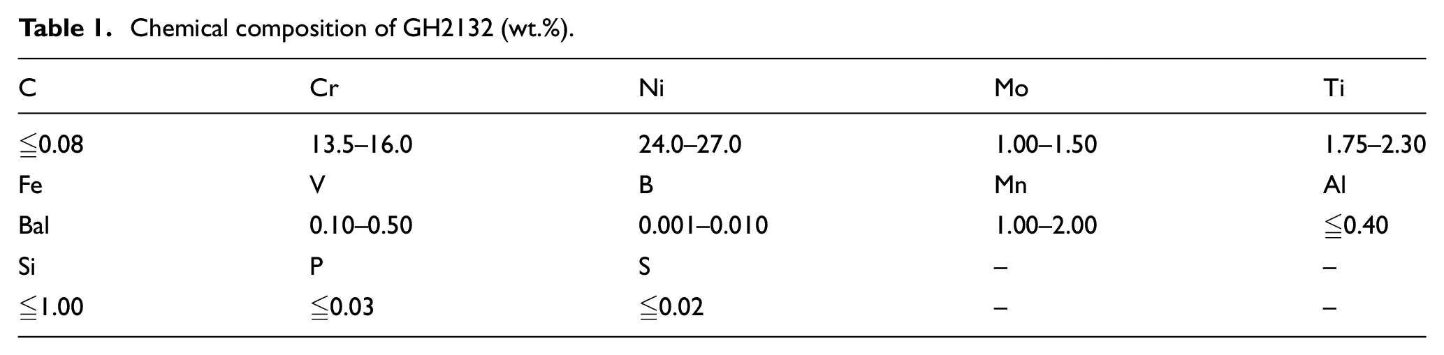
In the experiments, an age-hardening GH2132 superalloy bar with a diameter of 150 mm and length of 400 mm was selected as the representative workpiece. According to Guo et al., 5 its tensile strength and hardness at room temperature are approximately 1035 MPa and HRC 30, respectively. The elemental composition of the alloy is listed in Table 1.
Chemical composition of GH2132 (wt.%).
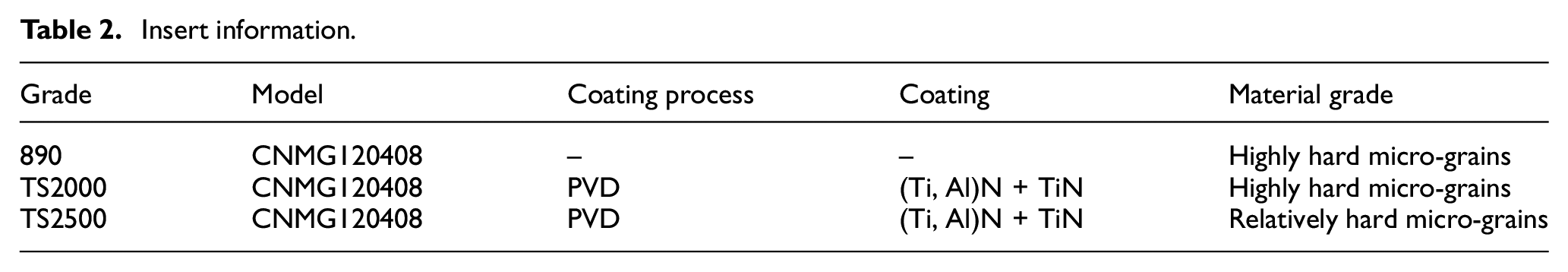
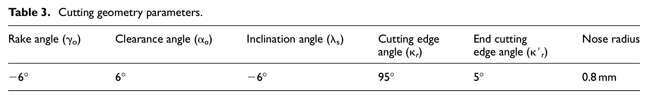
Three types of carbide inserts, namely, 890, TS2000, and TS2500 from Seco company, were used in the turning tests. Their specifications are presented in Table 2. TS2000 and TS2500, two coated carbide inserts specifically developed for machining superalloys, possess superior wear resistance. 23 Their external and internal coating is (Ti, Al)N and TiN, respectively. The toolholder (model DCLNR2525M12) with 95° cutting edge angle and 5° end cutting edge angle was selected in order to obtain favorable surface finish during the turning process. Cutting geometry parameters are listed in Table 3.
Insert information.
Cutting geometry parameters.
Experimental setup and test methods
The turning tests were performed using CA6140 lathe with a maximum speed of 1680 r/min and power of 7.5 kW. The turning experiment layout is shown in Figure 1(a). Cutting forces were measured using a system composed of a Kistler three-component dynamometer (model 9272), charge amplifier, data collector, and computer system. Cutting temperature was recorded using an FLIR infrared thermal imager (model A300). Wear values of the inserts were measured using an AM7915 Dino-Lite digital microscope. The observations on the wear morphology of the flank and rake faces were made by high resolution field emission scanning electron microscope (FSEM, TESCAN MAIA3 LMH, Czech Republic) system equipped with an energy-dispersive X-ray spectroscopy (EDS) system. The surface roughness was obtained employing a portable surface roughness tester (model TIME 3220).
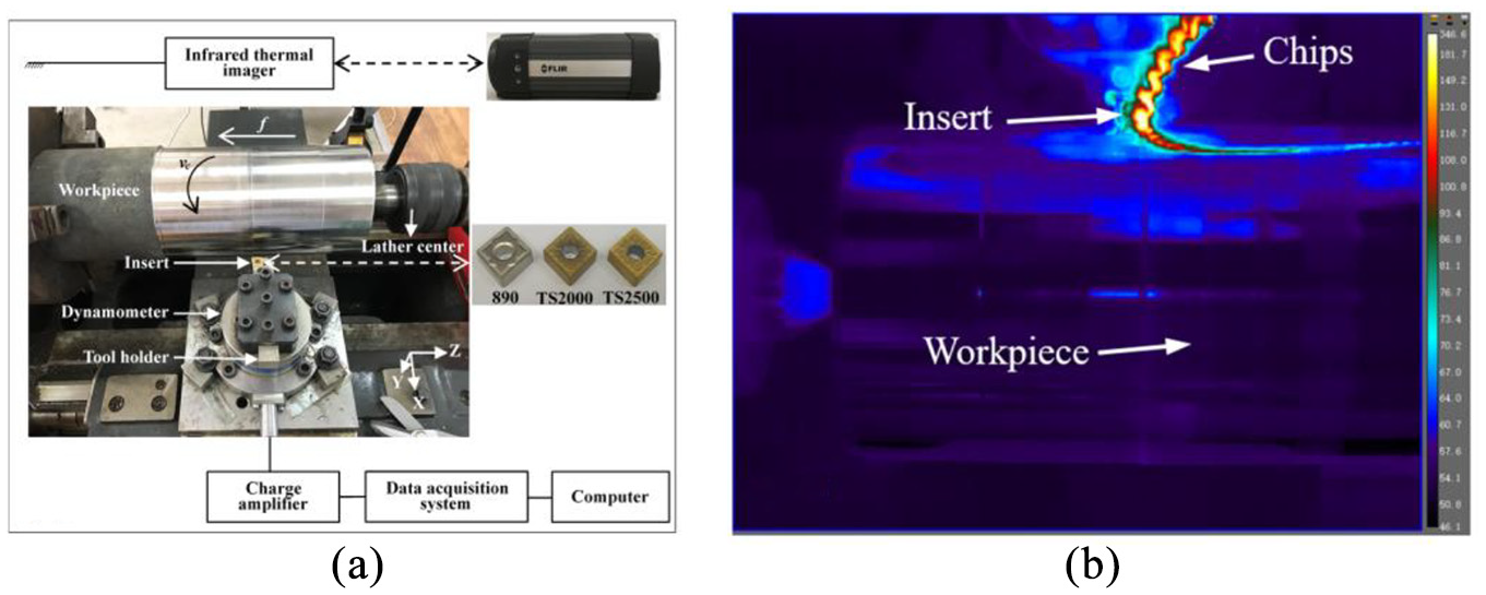
(a) Cutting experiment layout and (b) thermal imaging results.
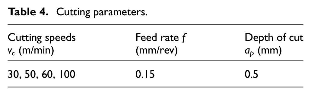
Single factor experiment methods were utilized in the turning tests. Table 4 summarizes the cutting parameters designed referring to the recommended values by Seco company. Cutting temperature and forces were recorded during the initial turning length of 50 mm. Then, along the feed direction, the roughness values of three different areas of the machined surface were tested and the mean value was obtained. Average wear value of the flank face was measured after the turning of certain length each time until VBave ≥ 0.3 mm was achieved. Finally, the wear morphology of the flank and rake faces was observed after cleaning and drying the failure inserts.
Cutting parameters.
The average values of the resultant cutting forces were calculated at different cutting speeds by using the following equation:

where n is the amount of sampling points, and Fxi, Fyi, and Fzi are the cutting force components of each sampling point, recorded using the dynamometer in X, Y, and Z directions, respectively.
Thermal imaging region of TS2000 at 50 m/min observed using the infrared thermal imager at one instant is shown in Figure 1(b), and the mean value of the maximum temperature in the initial turning length of 50 mm was used as effective cutting temperature.
Results and discussion
Cutting temperature, cutting force, and tool life
Figure 2(a) exhibits the results of cutting temperature at different cutting speeds. Obviously, with the increase in the cutting speed, the cutting temperature shows an increasing tendency. Owing to the low thermal conductivity of GH2132 and dry cutting condition, frictional heat rapidly accumulates at higher cutting speed, 24 which thus leads to rising cutting temperature. Furthermore, the cutting temperature of TS2000 was always the highest at the identical cutting speed. Compared to 890, the cutting heat of TS2000 was more difficult to dissipate owing to lower thermal conductivity of (Ti, Al)N coating. 23 Compared to TS2500, the friction between the insert and workpiece was more intense due to the higher hardness of TS2000 substrate as shown in Table 2. Digital micrographs exhibiting flank wear after initial cutting length of 50 mm (Figure 3) indicate that the intense friction makes TS2000 show more severe notch wear than TS2500 near the minor cutting edge, which contributes to higher cutting temperature.
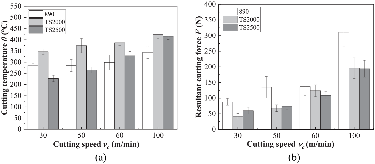
(a) Cutting temperature and (b) resultant cutting force at different cutting speeds.
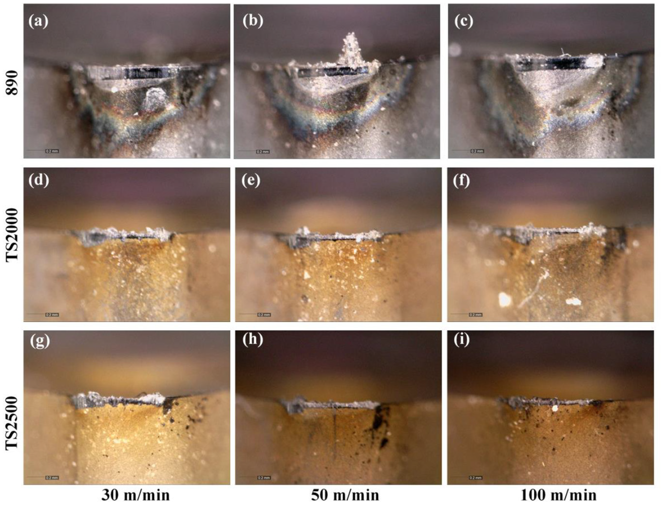
Digital micrographs exhibiting flank wear of the three tools after initial cutting length of 50 mm under (a), (d), (g) vc = 30 m/min, (d), (e), (h) vc = 50 m/min, and (e), (f), (i) vc = 100 m/min.
Figure 2(b) shows the resultant cutting forces versus cutting speeds, and the increasing trend is also observed. Although cutting temperature increases to above 450°C with the increase in the cutting speed as shown in Figure 2(a), the high hardness and strength of GH2132 are still maintained. Additionally, the flow speed of chip gets accelerated, and intense mechanical and thermal stress is generated. Moreover, the formation of adhesion layer increases with increasing cutting speed owing to excellent plasticity of GH2132. 25 These reasons account for the higher cutting force at higher cutting speed.
At the same cutting speed, the resultant cutting force of TS2000 and TS2500 is smaller than that of 890. At the initial cutting stage, the two coated inserts start wearing off from the (Ti, Al)N coating on the surface. On account of the lower friction coefficient of (Ti, Al)N, the friction between the inserts and workpiece is lower. 26 This alleviates adhesion of the rake faces and induces lower cutting forces. Flank wear micrographs of the three types of inserts, as shown in Figure 3, reveals that the average flank wear of 890 is larger than that of the coated tools, which indicates that the friction between the inserts and workpiece is more serious. As a result, the cutting force of 890 is the largest.
Figure 4 illustrates tool life of the three types of tools at different cutting speeds. Obviously, with increasing cutting speed, the tool life decreases sharply. As cutting speed increases, the tool bears higher cutting forces and cutting temperature as shown in Figure 2. Under higher thermal and mechanical load, in particular, thermal load, the mechanical properties of the cemented carbide tools decrease significantly and the coatings are easily to flake, and thus tool life decreases. Owing to the protective effect of (Ti, Al)N + TiN coating, the coated tools exhibit relatively longer tool life especially under higher cutting speeds. When the cutting speeds are 30 and 50 m/min, TS2500 shows better tool life, while at the cutting speed of 100 m/min, TS2000 exhibits better tool life.
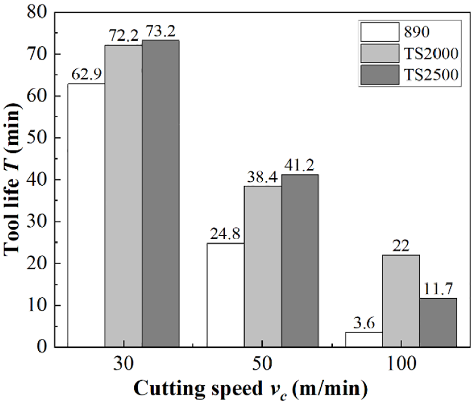
Tool life of the tools versus cutting speed.
Flank face wear
Figure 5 illustrates the wear distribution on the flank faces of 890, TS2000, and TS2500 inserts when they reach the failure criteria at vc = 50 m/min. Obviously, the wear concentrates on the region near the tool nose. The average wear width near the minor cutting edge is larger than that near the depth of cut. Diagram of the cutting area is shown in Figure 6, which reveals that under 95°cutting edge angle, 5° end cutting edge angle and 0.5 mm depth of cut, the tool nose arc acts as the main cutting edge and the chip thickness varies at different positions of the cutting edge. Continuous friction between major flank face and machining surface induces high temperature and large contact force, being the main reasons for tool failure. When the tool feeds, uncut material exists as shown in Figure 6(c) and it is plowed to the cutting edge in the form of side flow. The friction and extrusion effect of the uncut material and the serious work-hardening effect make the flank wear near the minor cutting edge larger.
Digital micrographs exhibiting flank wear of (a) 890, (b) TS2000, and (c) TS2500 at vc = 50 m/min.
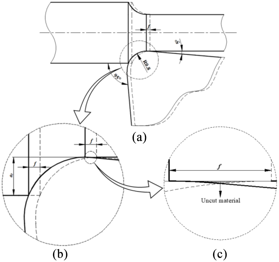
Diagram of the cutting area.
Figures 7 to 9 present FSEM micrographs of the flank wear at the depth of cut side of the three types of inserts at vc = 30, 50, and 100 m/min, respectively. Homogeneous wear is observed and the wear mode includes adhesion and abrasive wear.
Wear morphology of the flank face of (a) 890, (b) TS2000, and (c) TS2500 at vc = 30 m/min, and the partial enlarged detail of them exhibiting (d), (f) adhesion, and (e) three wear areas.
Wear morphology of the flank face of (a) 890, (b) TS2000 and (c) TS2500 at vc = 50 m/min, and (d), (e), (f) are the partial enlarged details of them.
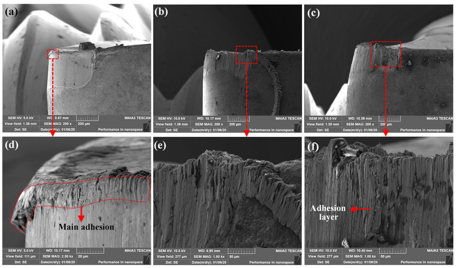
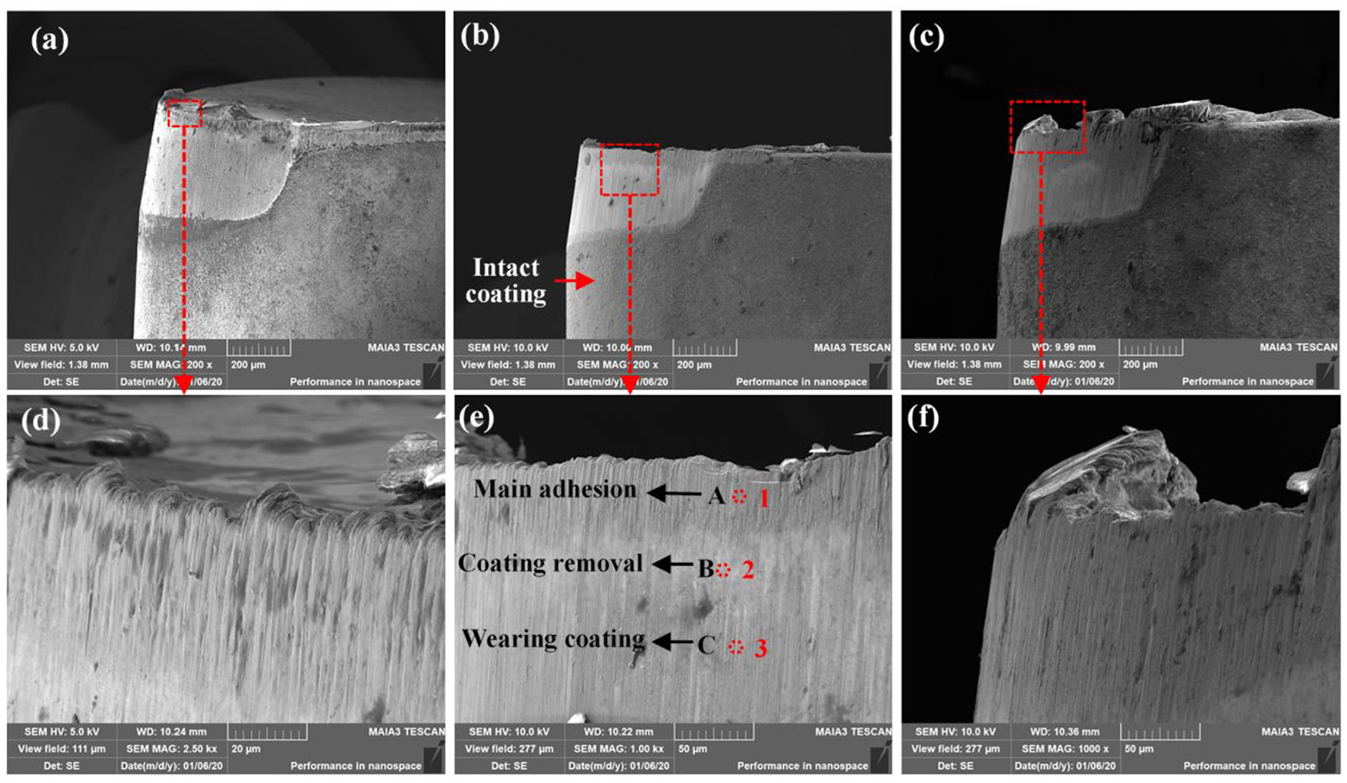
Wear morphology of the flank face of (a) 890, (b) TS2000, and (c) TS2500 at vc = 100 m/min, and the partial enlarged detail of them exhibiting (d) main adhesion area, (e) adhesion and chipping residual, and (f) adhesion layer.
The flank wear of TS2000 at vc = 30 m/min is shown in Figure 7(b) and (e) and it can be seen that the flank wear could be divided into the following three areas in the perpendicular direction: (1) Area A is the main adhesion area and the area shows more scratches. Analysis of the EDS result of the point 1 (see Figure 10(a)) confirms that materials in this area mainly come from the workpiece since most of the elements are Fe, Ni, and Cr. This is the evidence of adhesion wear. Since workpiece material is softer than the tool material, the scratches are more obvious than in other areas. (2) Area B is the coating removal area. It is dominated by the substrate material of the insert since the specific weight of W is as high as 75.46% based on the EDS result of point 2 (see Figure 10(b)). Some elements of the (Ti, Al)N + TiN coating, such as Ti (0.52%) and Al (1.69%), are observed, which indicates almost complete wearing off of the coating in this area. Furthermore, a few elements from GH2132 such as Fe, Ni, and Cr are also observed, indicating the occurrence of slight adhesion and diffusion. (3) Area C is the wearing coating area, and the major elements present in this area are N, Al, and Ti based on the EDS result of the point 3 (see Figure 10(c)), indicating incomplete wearing of the coating. Moreover, the total specific weight of Fe, Ni, and Cr is 23.2%, implying the occurrence of more serious adhesion and diffusion compared to area B. The intrusion of the workpiece elements, Fe in particular, can weaken the mechanical properties of the coating. 27 Similar wear characteristics can be found for 890 and TS2500 at vc = 30 m/min (Figure 7(a) and (c)) and 50 m/min (Figure 8(a) and (c)). As for TS2000, at vc = 50 m/min (Figure 8(b)), notch wear is more serious.
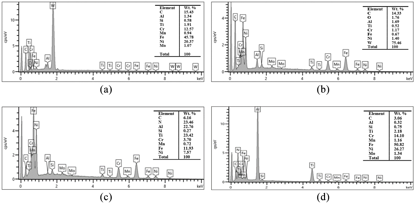
EDS analysis of (a) point 1, (b) point 2, (c) point 3, and (d) point 4.
When the cutting speed is 100 m/min, the tools show more serious adhesion wear as shown in Figure 9. For 890, the main adhesion area still concentrates near the cutting edge. For the coated tools, the main adhesion area nearly covers the flank face. Given the higher cutting temperature under higher cutting speed, the workpiece material and chips are more prone to adhere to the flank face of the insert because of its good plasticity and welding performance. Besides, the friction coefficient of TiN coatings increases with increasing temperature as stated by Deng and Liu. 28 Thus, the friction between the major flank face and machining surface increases when TiN coating begins to wear off after (Ti, Al)N coating is completely worn. Therefore, the major flank faces of the (Ti, Al)N + TiN coated tools show more serious adhesion while cutting GH2132 alloy at high speed. Adhesion layers can break and then carry off some tool materials, which results in adhesion wear. TS2000 still shows obvious notch wear at vc = 100 m/min as shown in Figure 9(b). Some adhered chip residual at the depth of cut is observed, which can increase the friction between the machining surface and major flank boundary, contributing to the generation of notch wear.
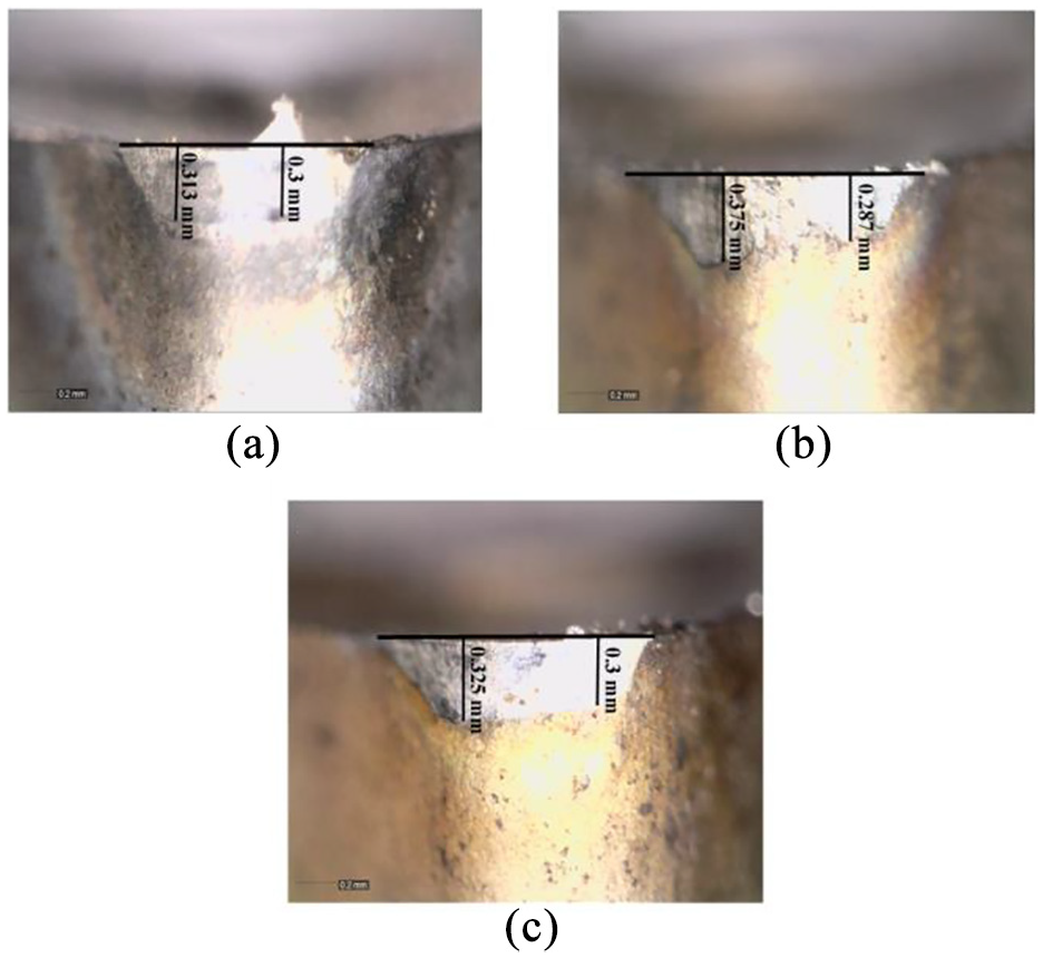
Flank face wear leads to the change of actual outline of the tools as shown in Figure 11. As a result, the actual clearance angle decreases and thus the friction between the insert and the machining surface becomes more serious. To evaluate the wear degree of flank face in the horizontal direction, tool wear gap value L when the tools reached the failure criterion was measured as shown Figure 12(a).
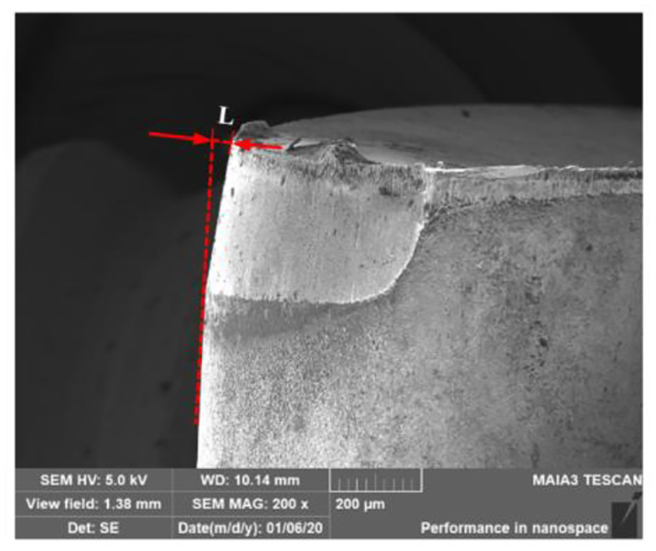
Measurement of tool wear gap of 890 at vc = 30 m/min.
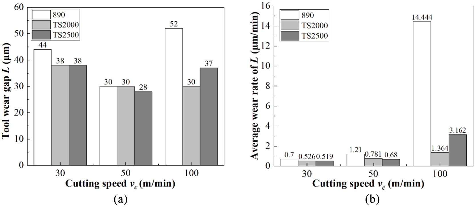
Results of (a) tool wear gap and (b) average wear rate of tool wear gap.
It can be seen that at the same cutting speed, the L value of TS2000 and TS2500 is not more than that of 890, while their tool life T is much longer (Figure 4). As shown in Figure 12(b), average wear rate of tool wear gap was calculated by L/T. Obviously, the average wear rate rises as cutting speed increases and that of 890 is always the highest. This is mainly attributed to the superior wear resistance of (Ti, Al)N + TiN coatings. The larger L also contributes to the higher cutting force of 890 as shown in Figure 2(b). If the wear happens along the radial direction of the workpiece, the actual diameter of machined components will be slightly larger than the theoretical value. In this respect, better dimensional accuracy can be obtained using the coated tools until they reach the failure criterion.
Rake face wear
Figure 13 to 15 show wear morphology of the rake faces of the three types of inserts at vc = 30, 50, and 100 m/min, respectively. The occurrence of built-up edge (BUE) and built-up layer (BUL) is observed. The BUL area of TS2000 and TS2500 is much smaller than that of 890, indicating that (Ti, Al)N + TiN coatings play a positive role in protecting rake face due to their superior wear resistance.
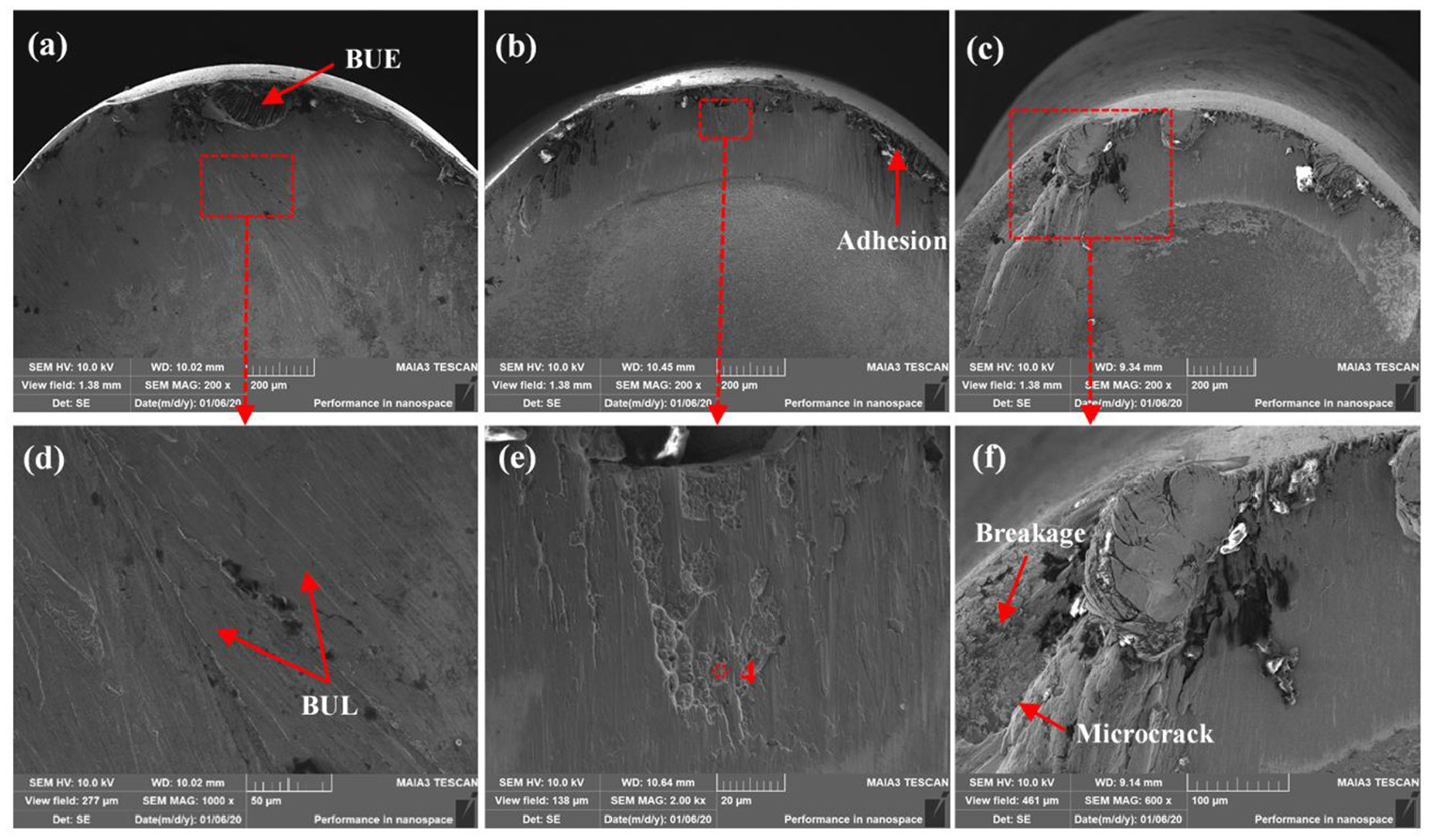
Wear morphology of the rake face of (a) 890, (b) TS2000, and (c) TS2500 at vc = 30 m/min, and the partial enlarged detail of them exhibiting (d) BUL, (e) pits and chipping, and (f) breakage and microcrack.
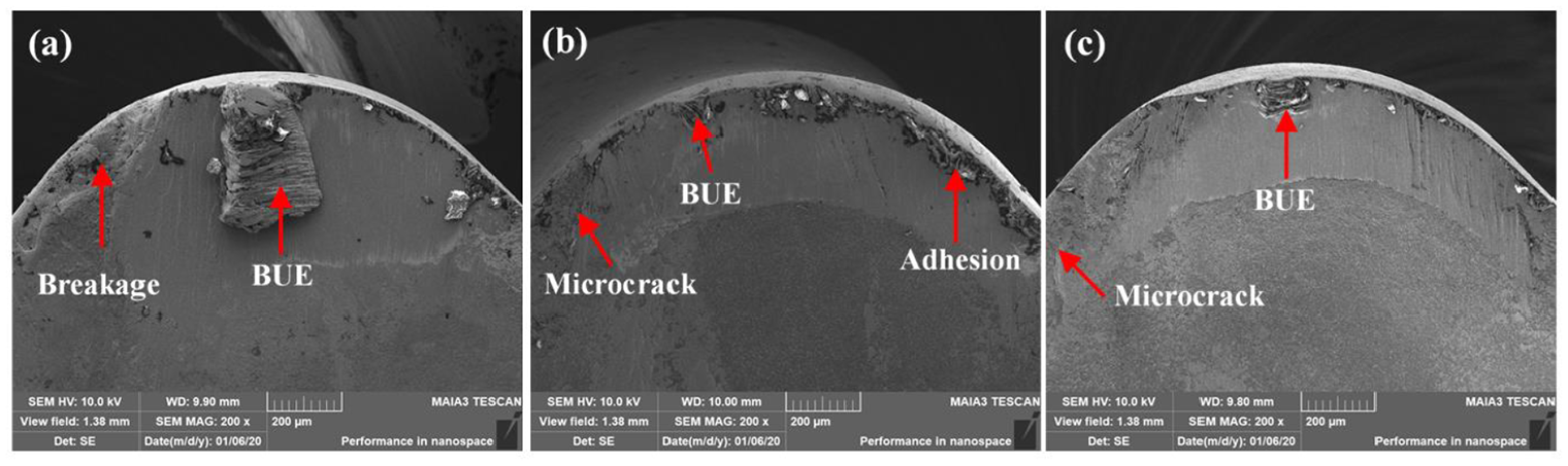
Wear morphology of the rake face of (a) 890, (b) TS2000, and (c) TS2500 at vc = 50 m/min.
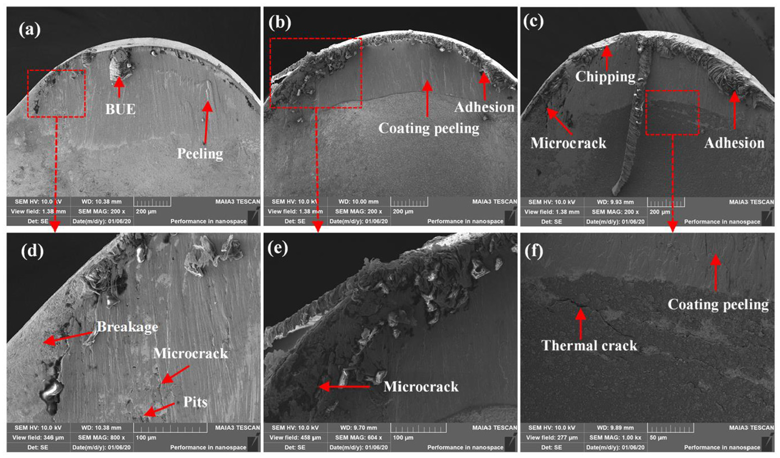
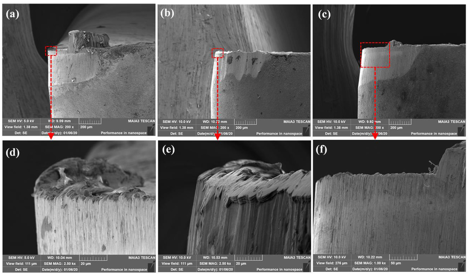
Wear morphology of the rake face of (a) 890, (b) TS2000, and (c) TS2500 at vc = 100 m/min, and the partial enlarged detail of them exhibiting (d) breakage, microcrack, and adhensive wear, (e) microcrack, and (f) coating peeling and thermal crack.
From these figures, it can be seen that BUE on TS2000 is relatively small under the three cutting speeds. This is attributed to its substrate with highly hard micro-grains as shown in Table 2, which improves adhesion resistance of the tool. Some small pits on the rake face of TS2000, as shown in Figure 13(e), are found under the cutting speed of 30 m/min. According to the EDS analysis of the point 4 (see Figure 10(d)), the elements belong to GH2132, indicating that the pits are produced due to the rupture of BUE since BUE is not stable during the cutting process. Similar phenomenon is also found for 890 at the cutting speed of 100 m/min as shown in Figure 15(d). The rupture of the BUE or BUL also takes away some tool material, which leads to the rake face wear.
Near the minor cutting edges, adhesion is much serious, in particular, at higher cutting speed as shown in Figures 14 and 15. On the cutting edges near depth of cut, slighter adhesion is observed, while cracks and breakage are distinct. It can be seen from Figure 6 that the shorter the distance to uncut material, the thinner the cutting layer. The thin cutting layer makes adhesion mainly concentrate on the cutting edge. At the depth of cut, the tools suffer serious thermal and mechanical stress. Considering the high hardness and brittleness of carbide tools, the large stress gradient at the boundary leads to cracks and breakage.
When the cutting speed is 100 m/min, coating peeling is observed for the coated tools as shown in Figure 15(b) and (f). TS2500 even produces thermal cracks in the intact coating area near boundary of BUL. This is mainly attributed to the high thermal stress at higher cutting speed. Furthermore, (Ti, Al)N coatings with low thermal conductivity not only limit dissipation of heat, but also generate huge temperature gradients between surfaces and interiors of the tools, 23 thus leading to the generation of thermal cracks. With the continuation of the cutting process, thermal cracks rapidly expand, and eventually lead to peeling of coatings. For the uncoated tool, the peeling of the substrate can also be found as shown in Figure 15(a). Besides, BUE still appears on the tool nose of 890, whereas it is smaller than that at relatively low speed.
As for the two types of coated tools, from Figure 15(b) and (c), it can be seen that TS2500 shows more serious adhesion and breakage than TS2000, and chipping also exists, which indicates that TS2000 has better cutting performance than TS2500 during dry cutting of GH2132 at higher cutting speed. This is consistent with the tool life analysis presented in Section 3.1.
Surface roughness
In general, surface roughness is applied to evaluate integrity of the machined surface. 29 Effects of the average flank wear values on the surface roughness are depicted in Figure 16. At vc = 30 and 50 m/min, the Ra values are between 0.5 and 1.2 μm, indicating that the carbide tools can provide relatively good surface finish during the dry cutting of GH2132. With the increase of mean flank wear VBave, surface roughness of the three types of inserts roughly shows a trend of first decreasing and then increasing and the minimum value is achieved at VBave ≈ 0.25 mm. New inserts have some unstable micro-convex bodies, burrs, and sharp cutting edges. 30 The higher Ra values for sharp cutting edges may be associated with the excessive chipping at the initial cutting process. After that, slight edge rounding along cutting edges is gradually generated, which makes the cutting process more stable and prevents the cutting edges from excessive chipping, and thus the Ra values reduce. 31 Furthermore, as shown in Figure 17, radial wear increases with the cutting process, which decreases the end cutting edge angle κ′ r and thus the residual area height also decreases. This also contributes to the decrease of surface roughness. After that, serious tool wear makes surface toughness increase.
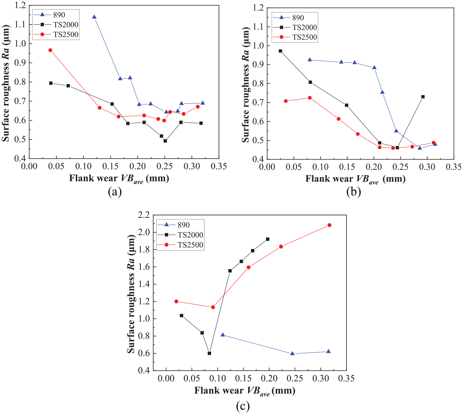
Effects of tool wear on surface roughness at (a) vc = 30 m/min, (b) vc = 50 m/min, and (c) vc = 100 m/min.
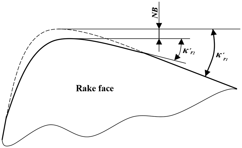
Decrease of end cutting edge angle due to radial wear.
Within VBave < 0.25 mm, TS2000 and TS2500 generate lower Ra values since (Ti, Al)N + TiN coatings possess lower friction coefficient compared to 890, and the reduced friction results in a better surface finish. After that, (Ti, Al)N+TiN coating of TS2000 and TS2500 is nearly completely worn out, which leads to a higher surface toughness than 890 as shown in Figure 16(b). The rising trend in the surface roughness also indicates that cutting performance of the carbide tools has significantly reduced and the tools are going to fail.
At vc = 100 m/min, the surface roughness of the three types of inserts still decreases first and then increases as shown in Figure 16(c). However, the turning point is at VBave ≈ 0.1 mm for TS2000 and TS2500. The coated tools induce much larger surface roughness compared with lower cutting speeds. Under high cutting temperature at higher cutting speed, the coatings are easily worn and peel off, and after complete wearing off of the coatings, the coated inserts generate serious adhesion, as illustrated in Figure 9(b) and (c), resulting in poor surface finish. Considering from the aspect of ensuring surface finish, (Ti, Al)N + TiN coated carbide tools are not suitable for machining GH2132 at higher cutting speed.
Conclusions
A series of dry turning experiments on GH2132 alloy was conducted with cemented carbide (Grade 890) and (Ti, Al)N + TiN coated carbide tools (Grade TS2000 and TS2500) and the following conclusions can be drawn.
Cutting temperature and the resultant cutting force increases while tool life decreases with the increase in the cutting speed from 30 to 100 m/min. The coated tool TS2000 with highly hard micro-grains substrate shows the highest cutting temperature. Owing to the protective effect of (Ti, Al)N + TiN coating, the coated tools show smaller cutting force and longer tool life.
Under 95° cutting edge angle and 5° end cutting edge angle, average wear width near the minor cutting edge is larger than that near the depth of cut.
At relatively low cutting speeds (30 and 50 m/min), the flank face wear of the three types of tools is dominated by abrasive and adhesive wear. At higher cutting speed (100 m/min), the flank face wear in 890 is still dominated by abrasive and adhesive wear while that of TS2000 and TS2500 is mainly severer adhesive wear.
The wear rate of the tool wear gap at the horizontal direction of TS2000 and TS2500 is smaller than that of 890. Consequently, that better dimensional accuracy can be obtained by using the coated tools until they reach the failure criterion.
BUE and BUL are the dominant wear morphology on the rake face. Adhesion wear near the minor cutting edge is more serious while breakage and microcracks are distinct near the depth of cut. At higher cutting speed (100 m/min), the peeling of the substrate for 890 and the peeling of the coatings for TS2000 and TS2500 are observed.
With the increase in the average flank wear, the surface roughness values roughly show a trend that first decreases and then increases. The coated tools generate lower Ra values compared to the uncoated tools. (Ti, Al)N + TiN coated carbide tools should be avoided for finishing applications of GH2132 under high cutting speed since the surface roughness sharply increases when the tools start to wear.
Footnotes
Appendix
Declaration of conflicting interests
The author(s) declared no potential conflicts of interest with respect to the research, authorship, and/or publication of this article.
Funding
The author(s) disclosed receipt of the following financial support for the research, authorship, and/or publication of this article: This work is supported by the Fundamental Research Funds for Central Universities (2017QNA15) and the Priority Academic Program Development of Jiangsu Higher Education Institution (PAPD).