
Abstract
During the design stage, the ideal simulation and visualization of the mechanical assemblies behavior require the modeling of parts with dimensional and geometrical defects. However, the deviations caused by parts deformations can generate an important difference between the ideal assembly and the real product. In this regard, this paper proposes a tolerance analysis method of CAD assemblies considering non-rigid joints between parts with defects. The determination of realistic rigid components with dimensional and geometrical defects is based on the worst case tolerancing approach and the Small Displacement Torsor (SDT) parameters. The Finite Element (FE) computation is executed to determine deformations of realistic non-rigid part models under external loads. Sub-algorithms to define non-rigid joints between realistic parts are developed. The tolerance analysis is established using the realistic CAD assembly. A case study is presented to evaluate the proposed model.
Keywords
Introduction
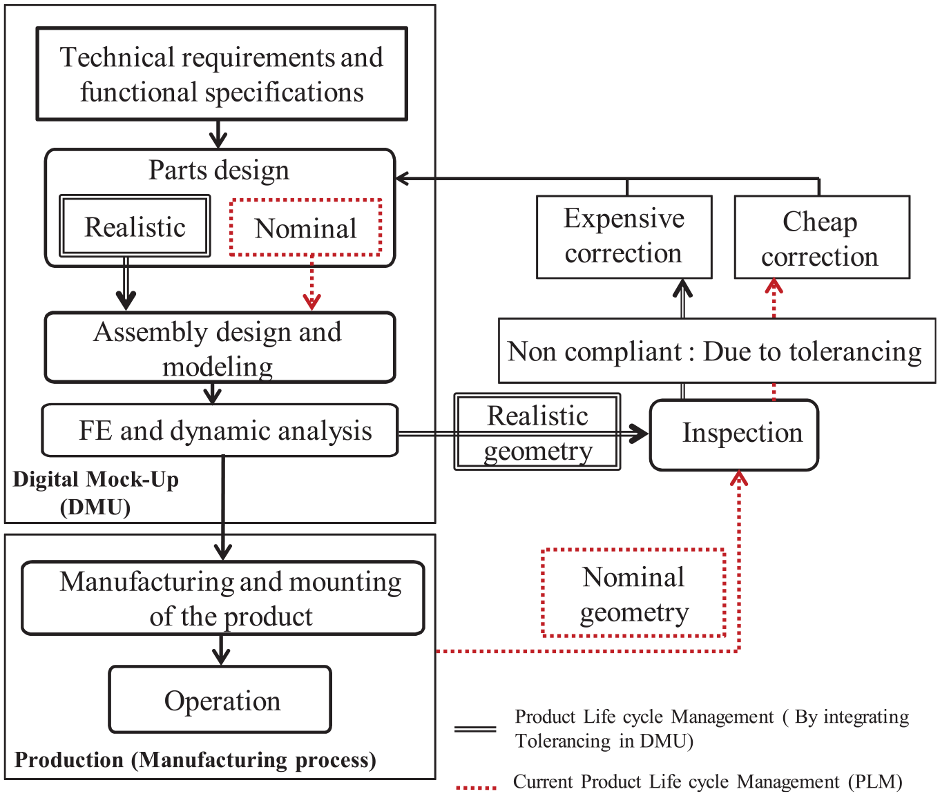
In the Digital Mock-Up (DMU), the modeling of assembly parts with manufacturing defects and the simulation of mechanical deformations of non-rigid components are two main phases required for the evaluation of the Functional Requirements (FR) during the product design (Figure 1). In the current Product Life cycle Management (PLM), the detection of tolerance impacts is made only after the product realization. The correction of the above errors at this stage requires additional costs. In this regard, several research works validated the need to consider tolerances during the calculation and simulation phases of the product.1,2 The above contributions allow avoiding all risks of malfunctions at the assembly process and during the system operation. Nevertheless, the realistic modeling of the assembly behavior during operation requires not just the consideration of geometrical and dimensional defects but also deformations of non-rigid components caused by various loads types. In this context, Korbi et al.3,4 and Tlija et al. 5 developed tolerance analysis models considering the above defects and using realistic CAD parts. Based on these models, non-rigid joints between realistic parts are not considered. Thus, this paper presents an improvement of the previous tolerancing methods through the development of new approaches to consider and define the joints between couples of non-rigid cylindrical and planar parts with defects.
The correction of the design defects dues to tolerances in an early stage of the product life cycle management.
The paper is organized as follows. First, a literature review of tolerance analysis approaches of assemblies with non-rigid parts is illustrated. Section 3 presents the main steps of the proposed tolerance analysis method of non-rigid parts assemblies. Sub-algorithms to redefine relationships between couples of Non-Rigid/Non-Rigid (NR/NR) realistic parts are proposed. A discussion section shows the model highlights and limitations. A case study is used to validate the steps of the proposed tolerancing method. The conclusion and perspectives of this work are presented at the end.
State of the art
Several models are developed to consider the manufacturing defects of parts during the tolerancing of mechanical assemblies. In this regard, Yu et al. 6 proposed an approach for the tolerance analysis of mechanical products based on the Product Of Exponentials (POE) formula. The individual parts deviations and cumulative variation propagations in the assembly resulted from dimensional and geometrical errors are determined using the twist coordinates and exponential maps respectively. The mathematical relation between the mechanism functional requirement and parts variations is determined from a non-linear stack-up function already derived from the POE. The statistical and worst case variations are analyzed based on the resulted explicit stack-up function. Cao et al. 7 presented a tolerancing method for three-dimensional tolerance analysis of mechanical systems using the quasi-Monte Carlo approach as well as the vector loop tool. The assembly response function is determined using the vector loop technique. The statistical tolerance analysis is executed based on the quasi-Monte Carlo algorithm. The above algorithm generates samples of the product functional requirement value according to the distribution of parts dimensions. The accuracy of the above tolerancing method is validated using actual case studies.
Numerous contributions are proposed for the integration of tolerances in CAD models. Louhichi et al. 8 and Tlija et al. 9 developed approaches to model rigid parts with positional and orientation defects in order to evaluate the functional requirement of mechanical assemblies in CAD. Jbira et al. 10 improved the method of Louhichi et al. 8 by considering form defects in tolerance analysis.
The above tolerancing methods consider the rigid configuration of assembly parts and neglect the deformation of non-rigid components. Thus, a significant amount of research works proposed tolerance analysis methods considering the deformations of non-rigid parts. On this topic, Liu et al. 11 established a model for the tolerancing of flexible sheets metal assemblies. A mathematical model based on the use of the Method of Influence Coefficient (MIC) is established to estimate the impact of deformations on the tolerance specifications of a set of sheet metal assembled in parallel or in series. In the automotive industry, Hermansson et al. 12 proposed a set of simulation methods for the study and the control of the geometric variation in deformable cables and hoses. The above methods are based on the calculation of the optimal tolerance envelopes of each assembly component in order to avoid all risks of interferences or mountings between parts. Söderberg et al. 13 developed an approach to study the effect of the spot welding position variations on the geometrical behavior of sheet metal assemblies. Indeed, three main factors act on the spot position, such as parts geometrical deviations, positioning variations of components to be assembled and tooling errors. In the aeronautical industry, Mei et al. 14 presented a method for the variation modeling and analysis in the case of compliant structures’ assemblies. The dimensional variation sources of the assembly parts are represented with interval structural parameters. The MIC and the interval arithmetic operations are used to compute the global assembly variation considering the deformation of assembly components. Warpage and torsion angles are used to facilitate the computation of assembled parts deformations during the Finite Element Analysis (FEA), without considering key points deviations on parts surfaces. The proposed variation analysis approach results are validated with experimental data. Mazur et al. 15 presented a multidisciplinary tool called Process Integration and Design Optimization platform (PIDO) for the tolerance analysis and synthesis of assemblies subjected to external and internal loads. This Platform uses several engineering disciplines such as Monte Carlo simulation as well as the multi-objective genetic algorithm to evaluate the tolerances values attributed to the assembly parts and to find if necessary optimal tolerances. Liu et al. 16 proposed a method for the assembly variation analysis using the rigid–flexible hybrid vector loop. First, surfaces and sidelines shapes of parts are determined according to tolerance types and values. In fact, statistical methods are used to estimate the probability density distributions of discrete feature points on the toleranced part surface. After that, the vector-loop model of flexible parts is determined through the discretization of the part surface into a set of vectors describing the position information and the error size. The unified vector-loop model is obtained by combining the vector loop model of the flexible part with the classical rigid component vector. The assembly deformations are predicted using the above rigid–flexible vector loop model and the FE analysis. The assembly variation values of products key features are computed based on the probability density distributions of discrete feature points on rigid and flexible parts surfaces. Guo et al. 17 proposed a tolerance analysis method based on the consideration of manufacturing deviations and assembly components deformations. The geometrical defects are calculated using a homogeneous transformation matrix. Moreover, the FE computation is applied to deduce parts deformations by considering both normal and friction forces on the contact zone. Pierre at al. 18 established a tolerance analysis model for hyperstatic mechanisms that considers the maximum and the minimum of material conditions of parts with defects as well as deformations dues to the mechanical joints forces. Zhang et al. 19 developed a method for the tolerance analysis of annular surfaces considering form defects and local surface deformations dues to external loads. Form defects are taken into account based on the skin model concept. The Boundary Element Method (BEM) allows computing local surface deformations. The tolerance analysis is conducted using the Monte Carlo simulation. Camuz et al. 20 proposed a tolerance analysis framework considering the contact forces and fluctuations between two surfaces during the cutting operation in machining. In this case, the surface- to- surface contacts variation is analyzed using the FE calculation.
Other researchers integrated the deformations due to thermal effects in the tolerance analysis process. In this context, Jayaprakash et al. 21 considered both the thermal effect and inertia to establish an optimal tolerance design approach for mechanical assemblies. Pierre et al. 22 developed a method based on torsorial formulations to model the relationship between the thermal effects and the geometrical deviations of assembly parts.
The methods presented in Refs.6–10 do not satisfy the industrial needs to consider the impact of parts deformations during the tolerance analysis of mechanical assemblies. The approaches proposed in Refs.11–22 overcome the limitations of the above tolerancing methods by taking into account the deformations of non-rigid components. Most of these methods11–14 can be applied just in the case of sheets metal assemblies and are not valid for thick parts. The rest of models15–22 are focused on the use of mathematical formulations, statistical tools and the FE computations without a realistic geometric modeling of assembly components on the CAD software. Thus, this paper proposes a new CAD method for the consideration of manufacturing defects and deformations of non-rigid parts during the tolerance analysis of CAD assemblies. Indeed, the main paper goals are:
The modeling of realistic non-rigid parts: dimensional and geometrical tolerances as well as deviations caused by deformations are considered in CAD component.
The modeling of planar and cylindrical joints between non-rigid parts with defects.
The tolerance analysis considering parts motion.
Tolerance analysis method of non-rigid parts assemblies
To overcome the limitations of the tolerance analysis methods of non-rigid parts assemblies already exist in the literature, a new CAD model is developed to consider geometrical and dimensional defects as well as deformations of non-rigid components at the tolerancing stage. As an assumption, orientation and positional tolerances are just considered while modeling rigid parts with defects. Form defect are neglected. The deformations considered in this paper are caused by external loads. The proposed model is based on several engineering tools such as CAD, the FE simulation and the tolerancing. The flow chart (Figure 2) shows the main steps of the developed method:
Definition of the CAD inputs. - Geometrical and dimensional tolerances (G&D tolerances). - The Assembly Sequence (AS). - The Functional Requirement of the assembly (FR).
CAD Modeling of realistic components (Rigid and Non-Rigid parts): The worst case concept and the SDT tool are used to model rigid parts with manufacturing errors considering dimensional and geometrical tolerances limits (Sub-algorithm 2). The realistic modeling of non-rigid components is established according to two scenarios: with or without tolerances. If the part is defined without tolerances, then the nominal CAD model is used during the FE computation (Sub-algorithm 3). However, if geometrical and dimensional tolerances are assigned initially to the non-rigid part features, then the part is supposed temporarily as rigid and the worst case configurations are determined before processing for the FE computation (Sub-algorithms 2 and 3) (Figure 2).
CAD Modeling of the realistic assembly (The update of the assembly mating constraints between realistic components especially in the case of NR/NR joints).
The control of FR (Tolerance Analysis).
The search of correct tolerances values allowing the respect of the FR (In case FR is not satisfied).
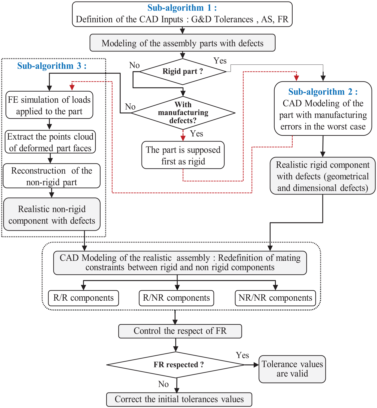
Main steps of the developed method.
Modeling of realistic rigid and non-rigid components
In the proposed approach, the realistic rigid and non-rigid components configurations with defects are determined using the following sub-algorithms:
The first sub-algorithm defines the model inputs. The CAD data are considered as the inputs of the developed model, such as tolerances types and values, the Assembly Sequence Order (ASO), and the FR (Figure 2). The above inputs are determined based on the nominal 3D assembly. The ASO is defined from the mating constraints between each couple of parts already classified in the tree feature manager of the CAD software.
Using the sub-algorithm 2, the assembly parts are modeled in the worst case realistic configuration according to the geometrical and dimensional tolerances limits.
8
As mentioned above, at this stage the non-rigid part, subjected to tolerances, is considered temporally as rigid (Figure 2 (Red Path)). The dimensional tolerances are represented geometrically on CAD components considering two possible scenarios: The maximum and the minimum of material. In CAD software, the tolerances are specified on driven dimensions and the part model is defined by driving dimensions. To consider the dimensional tolerance in CAD model, the relationship between the driving dimension Pi (with VPi value) and driven dimensions Cj (with VCj value) of the CAD component must be quantified. Thus, an automated algorithm is developed based on the definition of a specific coefficient called “coefficient of influence βij” (Figure 3). This coefficient is equal to the ratio between the variation

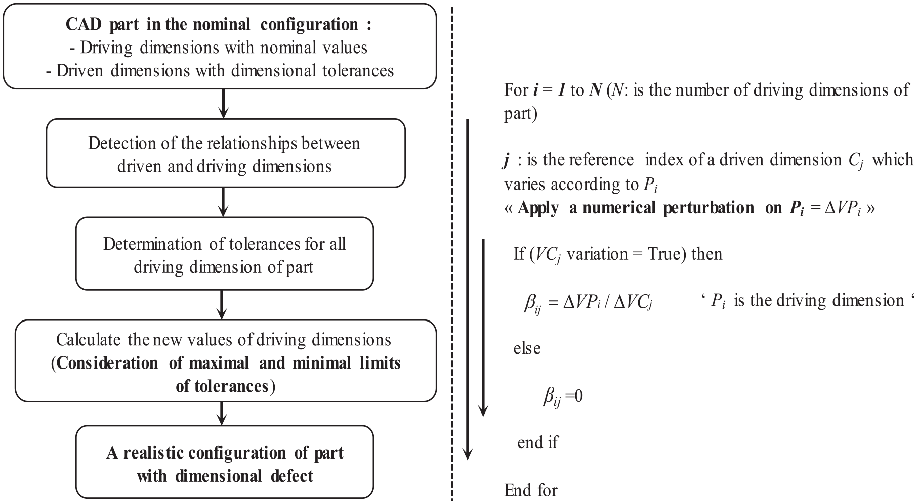
The algorithm used to calculate βij by the numerical perturbation method.
To model rigid parts with geometrical defects, the worst case tolerancing approach and the SDT parameters are used. In this case, the toleranced feature geometry and the tolerance type should be identified in order to determine the worst case configurations of parts with defects. Thus, a sub-algorithm is developed in the Application Programing Interface (API) of SolidWorks software to automate the following tasks:
The detection of the toleranced part features with geometrical tolerances.
The determination of the worst case face or axis displacements (Rotations/Translations) of planar and cylindrical parts respectively, using the SDT parameters and tolerances limit values. The Figure 4 shows the case of the perpendicularity tolerance applied to the planar face.
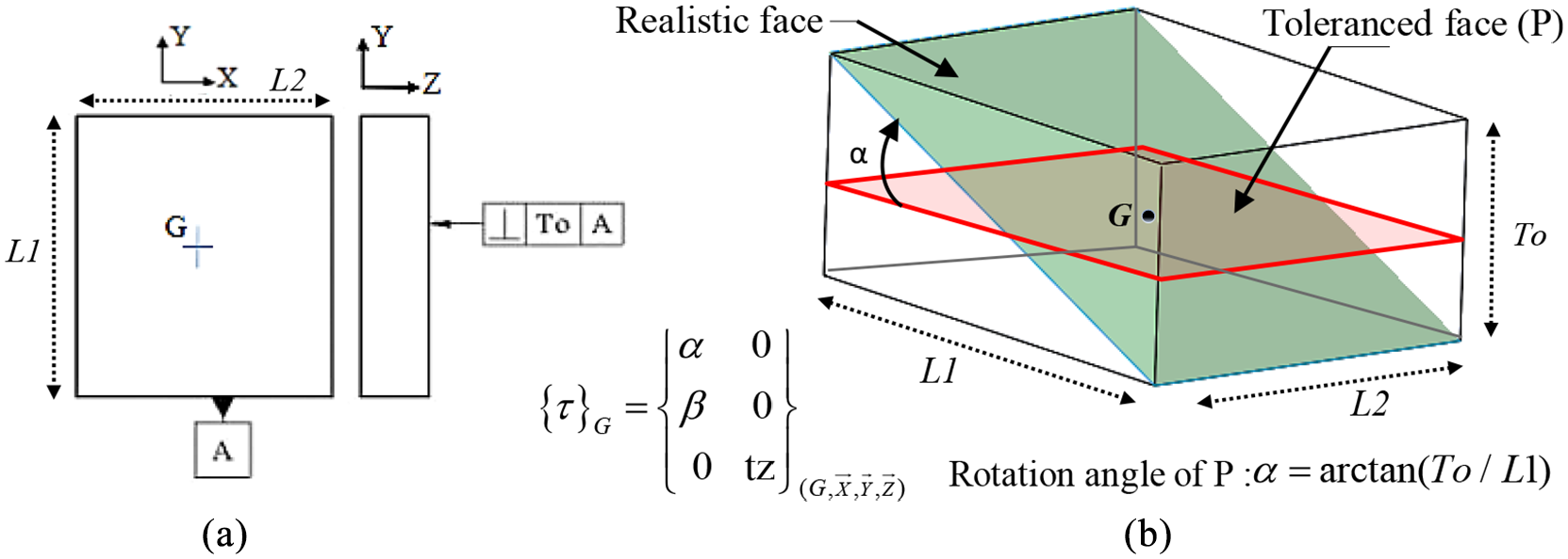
(a) Geometrical tolerance attributed to a planar part face and (b) realistic face resulted from a worst case rotation (with an angle α).
To determine realistic configurations of non-rigid parts with deformations defects, the sub-algorithm 3 is applied. As mentioned above, if the non-rigid part is defined with tolerances, then the sub-algorithm 2 is used before applying the sub-algorithm 3 (Figure 2). First, the designer selects the components to be considered as non-rigid. Usually, the most stressed part, that the deformations resulting from external loads may affect the system functioning is chosen as non-rigid. Indeed, this choice is not automated in the proposed model. After that, each non-rigid part of the assembly subjected to external loads is isolated from the assembly and the FE computation is executed. As an assumption, the contact forces between the assembly parts due to external loads are neglected. Several steps are executed to process for the FE simulation and are listed as follows:
Apply the boundary conditions and external loads to the part.
Define the part material and apply the mesh (define mesh tolerance and size).
Run the FE calculation.
Once the FE calculation is finished, two tasks are executed:
Check and control the maximum stress of the deformed face of the part: The elastic limit of the part material must not be exceeded, and the nodal displacements must not be outside the tolerance limits.
The nodal displacements of each deformed face with or without geometric and dimensional defects are extracted and saved in an Excel file (Figure 5).
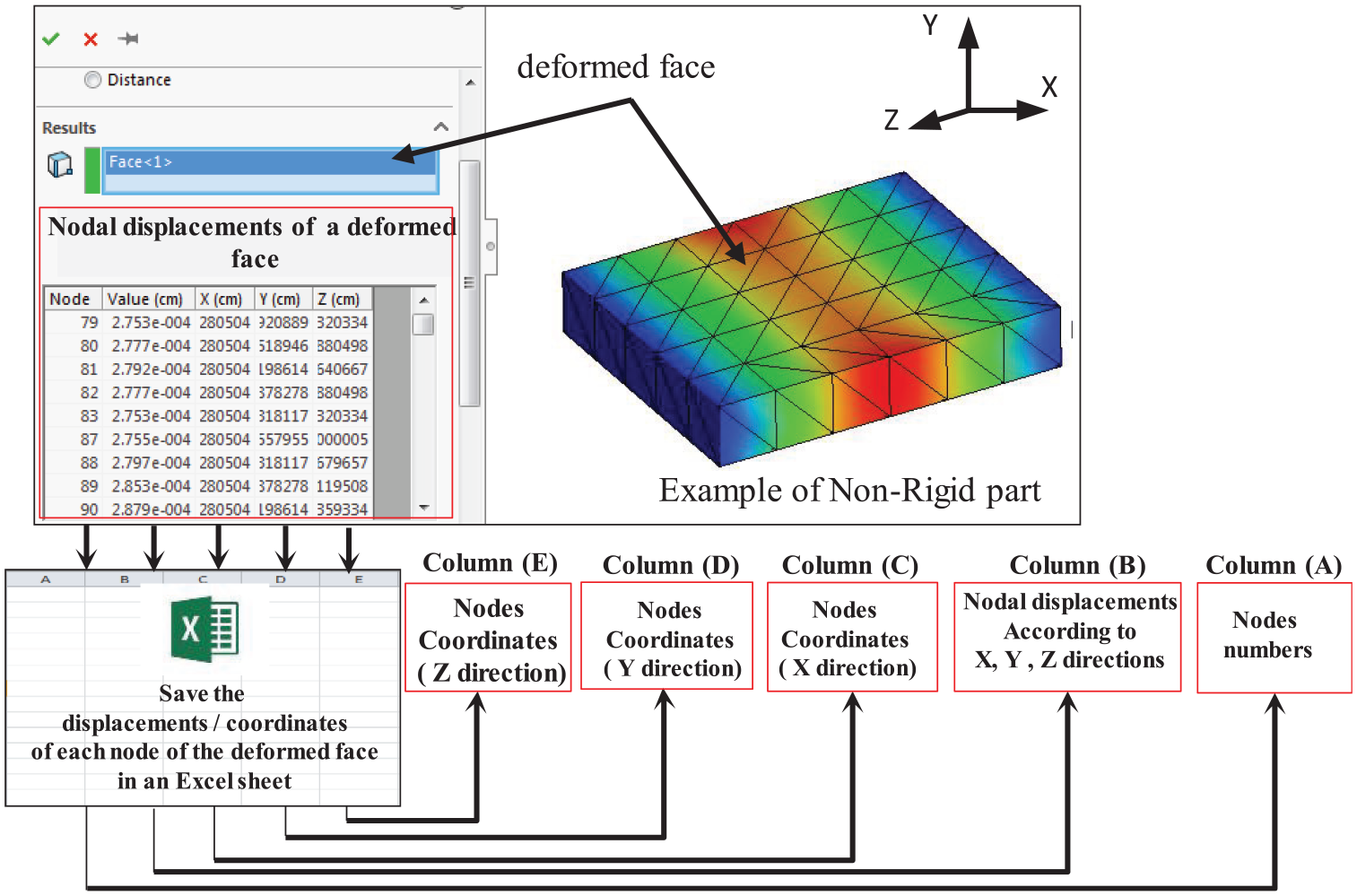
Extraction of nodal displacements of the deformed face after the FE computation.
Based on the FE results, the elementary mesh nodes displacements of each deformed face of a stressed assembly component are added to the coordinates of initial nodes of the face before deformation. The result of the above addition corresponds to the points cloud of a realistic face with defects (equation (2)). In the case of planar and cylindrical faces, the calculation of the points cloud coordinates corresponding to each deformed feature is performed by adding the nodal displacements values resulting from the FE simulation to the coordinates of the face initial points in the nominal configuration (before deformation) (Figure 6). This step is automated using a sub-algorithm based on the API of SolidWorks® and MS Excel.

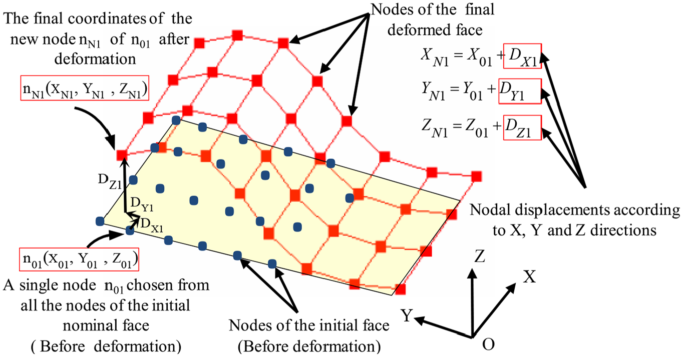
Determination of the points cloud of a deformed planar face.
Once the points cloud of each deformed face are obtained, the Digitized Shape Editor(DSE) tool of CATIAV5® software is used to triangulate the above points and to generate the STereLlithography (STL) file that contains all the triangulation data (Figure 7).This tool is accurate, fast, and efficient especially in the case of very dense point clouds.
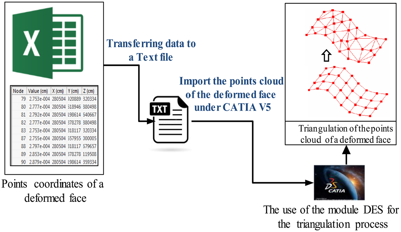
The process of transferring the points cloud data of a deformed face from the FE simulation to the DES triangulation tool.
After the triangulation process, the STL file that contains the data of the triangulated points cloud is imported under SolidWorks® in order to reinsert these points on the nominal part (Figure 8). This work is applied for all deformed faces of the non-rigid component.
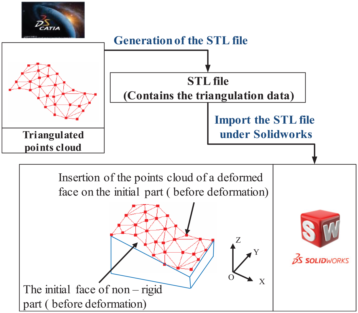
The strategy used to insert the triangulated points cloud of a deformed face on the initial non-rigid component.
In order to reconstruct the final realistic geometry of the non-rigid component with the deformation defect, elementary triangular surfaces, considered as reference surfaces, are created from the triangulation elements linked the points of all deformed faces. The above reference surfaces are combined in order to construct the new shapes and configurations of deformed features (faces) of realistic non-rigid components in the CAD environment (Figure 9(a) and (b)).
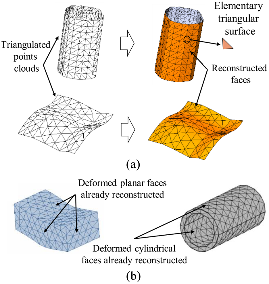
(a) Reconstructed cylindrical and planar surfaces and (b) the final configuration of two non-rigid cylindrical and planar components after the reconstruction phase.
All the above methods assist engineers and designers to obtain the realistic configurations of rigid and non-rigid components with defects to be reused in the CAD model.
Determination of the realistic CAD assembly configurations
The mating constraints between couples of NR/NR realistic parts are redefined to obtain the final realistic CAD assembly. The methods of updating the relationships between Rigid/Rigid (R/R) parts and between Rigid/Non-Rigid (R/NR) parts are already established in Louhichi et al. 8 and Korbi et al.3,4 respectively. The update of a coincident constraint between NR/NR planar and cylindrical parts is described in the following sub-sections.
Modeling of the planar joint between NR/NR parts
The initial coincident constraint, between NR/NR planar faces
Coincident constraint (
Coincident constraint (
Coincident constraint (
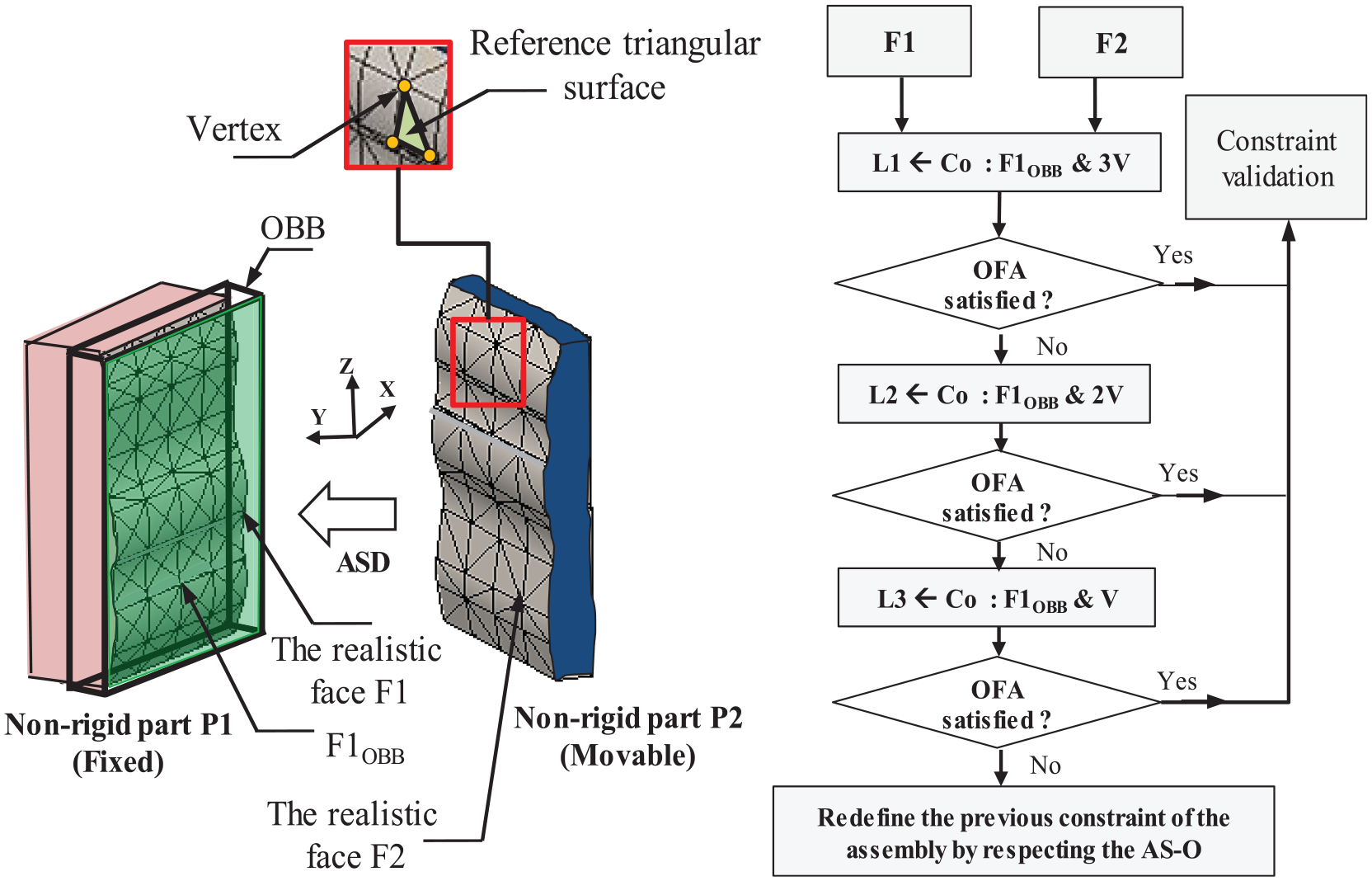
(a) The use of the OBB of the realistic face
Modeling of the cylindrical joint between NR/NR parts
In the case of a cylindrical joint between NR/NR parts, the axes
The realistic axis
The realistic axis
After the reconstruction of realistic axes
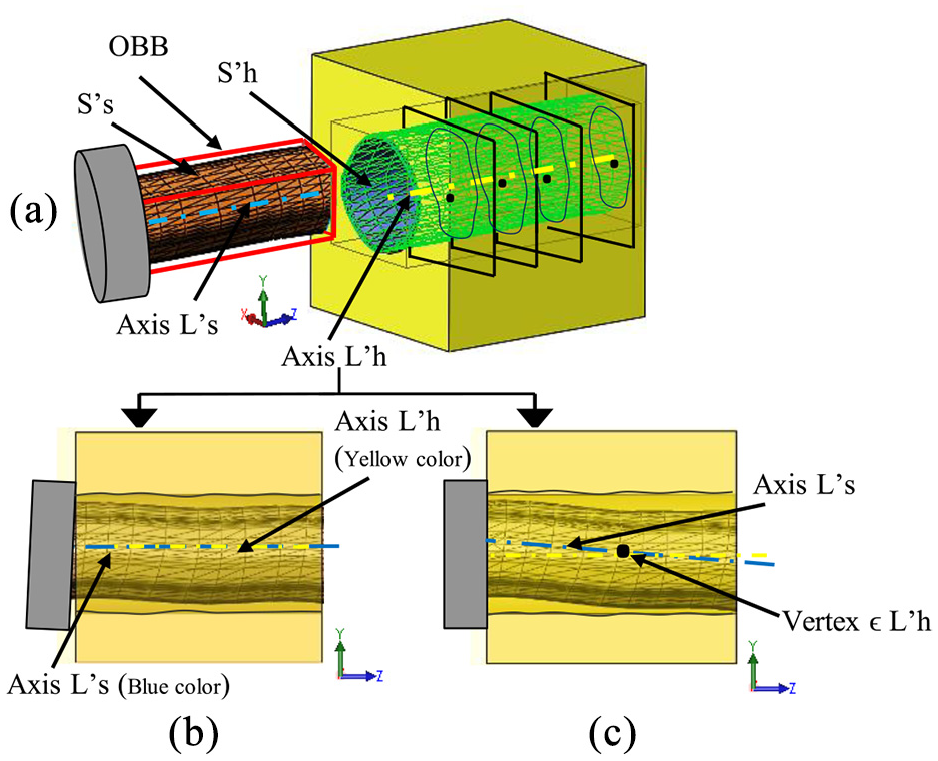
(a) Axes
Tolerance analysis
The tolerance analysis aims to control the FR after updating the mating constraints between all couples of the realistic assembly parts. The above task is established while considering the relative motion between parts. This motion simulates the assembly operation. In case of the FR satisfaction, the tolerances values already specified in the nominal configuration are conserved. However, if FR is not respected, an iterative sub-algorithm is used to find tolerances values to be modified based on the sensitivities analysis method (identify and classify tolerances according to the impact degree on the FR) and tolerances cost. Generally, the less expensive tolerances are chosen first to be corrected considering an increment
Discussion
The proposed tolerancing approach uses several sub-algorithms to model rigid and non-rigid parts with defects. The worst case concept and the SDT parameters are chosen to determine realistic rigid components configurations with dimensional and geometrical errors (Sub-algorithm 2). Indeed, in this paper, the assumption of obtaining the worst case assembly by the stack-up of components in worst case configurations is adopted. The SDT tool is commonly used by several tolerancing methods of rigid parts assemblies to mathematically model tolerances based upon the movements of a rigid body 25 and is easy to be implemented in CAD softwares.10,26 Generally, the worst case modeling of dimensional and geometrical parts variation is fast (runtime) and easy to be performed using CAD tools compared to statistical tolerancing approaches. Despite the statistical tolerancing considers the random aspect of the part manufacturing, it remains used moderately. 27 One of the causes of this low use is undoubtedly the difficulty for designers to predict the risks of these approaches because of their complex definitions. Unlike traditional worst case tolerancing, statistical tolerancing requires a sustained exchange of information between the design and manufacture to be used safely. Based on the above details, the worst case method is chosen in this work for the modeling of rigid parts with manufacturing errors. On the other hand, the non-rigid parts are modeled in the realistic configuration considering the deformations resulted from the FE analysis. The designer chooses parts to be considered as non-rigid, such as the algorithm runtime is proportional to the number of non-rigid components in the assembly. As mentioned before, in case of tolerances are attributed to the non-rigid part features, the realistic part features configurations with manufacturing errors are determined in addition to the FE calculation. At this step, the use of the statistical tolerancing generates more realistic configurations than worst case tolerancing and increases simulations complexity and runtime.
The realistic assembly is created by the redefinition of mating constraints between realistic rigid and non-rigid components. Thus, the tolerance analysis is performed during the relative parts motion. The main contribution of this paper is the CAD modeling of non-rigid assembly joints considering manufacturing errors during the tolerancing process. Indeed, the consideration of the combined effects of deformations and manufacturing defects in the CAD environment overcomes the limitations of the methods previously cited.6–22 The runtime of the developed decision aided tool depends significantly on the number of components and initial specifications. Nevertheless, the current state of affairs in this research field and the works so far seem very promising and may serve as an impulse for abundant discussions in research and industry.
Case study
In this section, a case study is used to validate the steps of the developed tolerancing method. A steam engine assembly with fixed cylinder (Figure 12) is considered and composed of the following components with geometrical tolerances:
The crank support (1) considered as Non-Rigid with position defect
The connecting rod pin of axis (
The connecting rod (4) considered as Rigid with parallelism defect
The crank axis (3) considered as Non-Rigid with coaxiality defect
The other components (5), (6), (7), (8), and (9) are Rigid without defects.
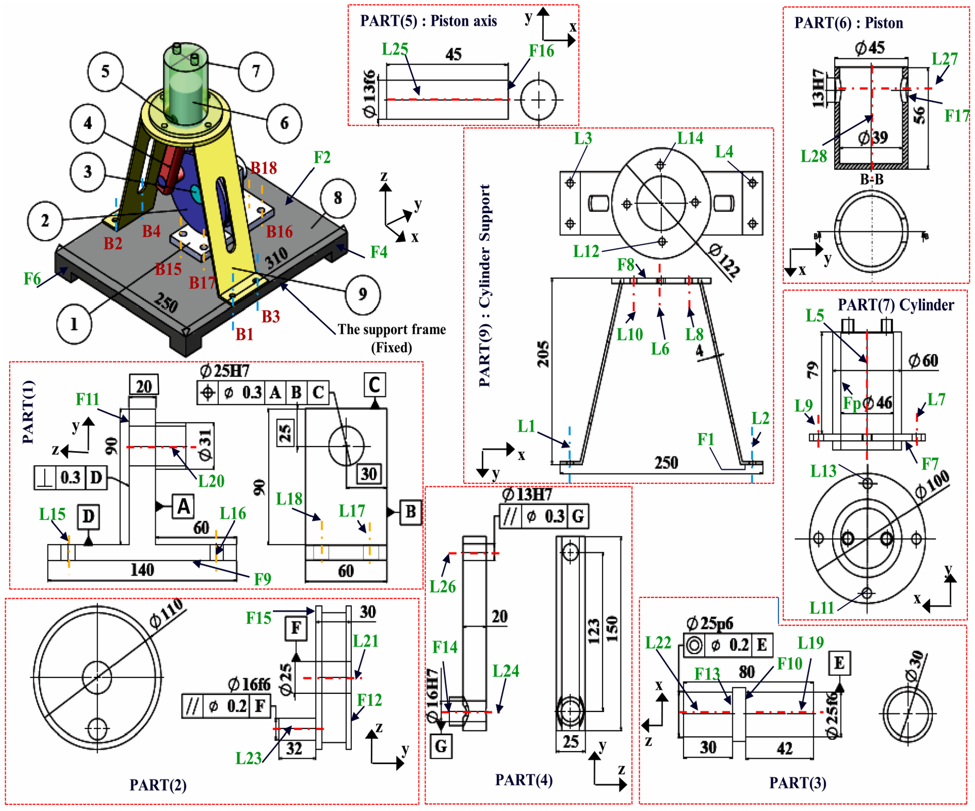
Drawing of the steam engine assembly with fixed cylinder.
The functional requirement of the assembly consists of keeping the clearances between the piston and the cylinder (
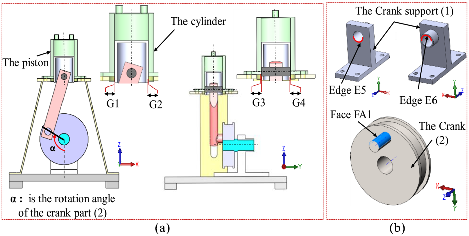
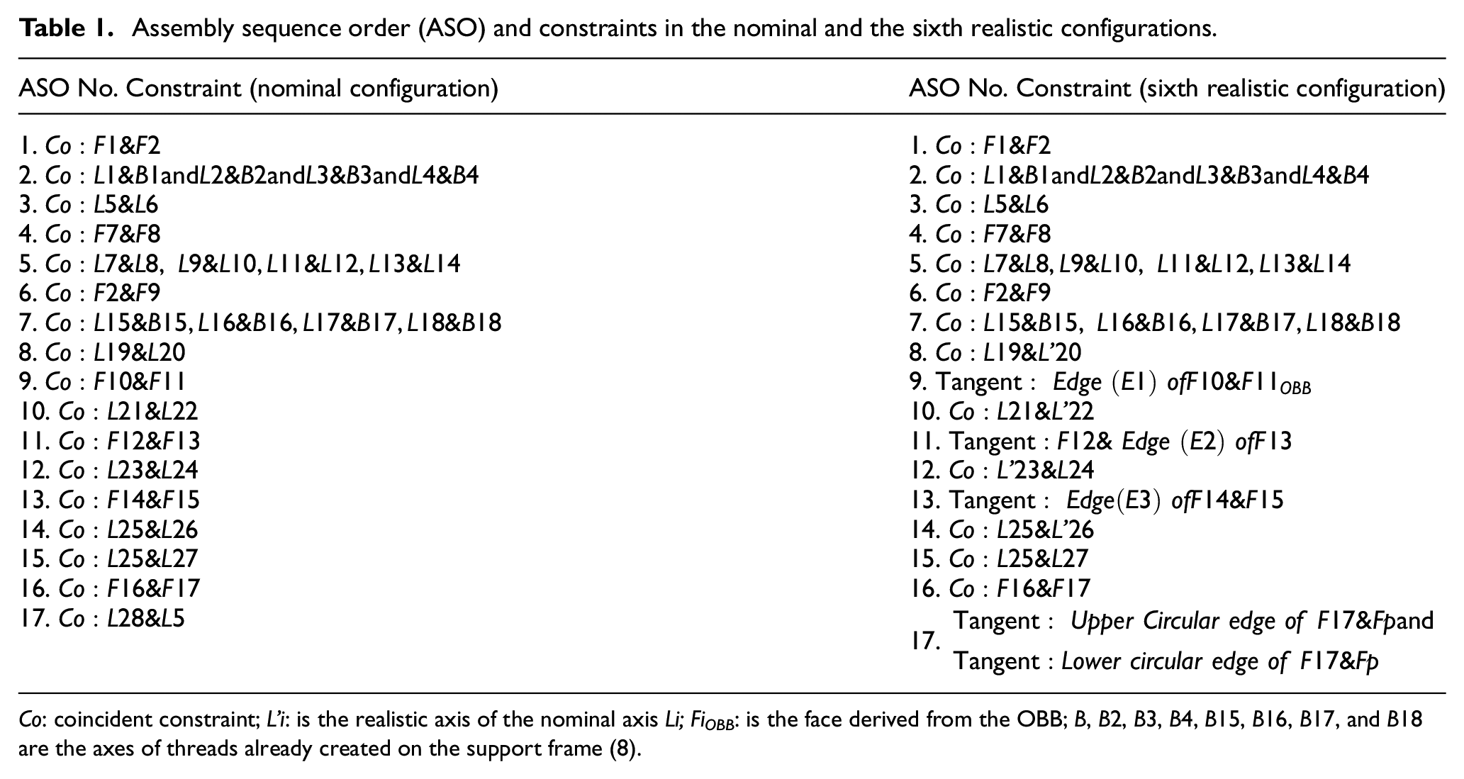
(a) Clearances G1, G2, G3, and G4 between the piston and the cylinder and (b) edges and faces of non-rigid parts already subjected to loads (used in the FE step).
Two null values of
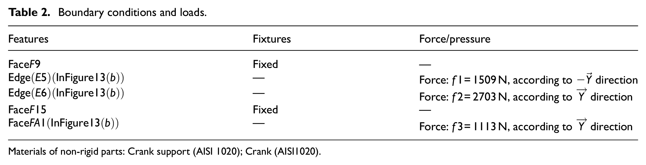
Assembly sequence order (ASO) and constraints in the nominal and the sixth realistic configurations.
Co: coincident constraint; L’i: is the realistic axis of the nominal axis Li; FiOBB: is the face derived from the OBB; B, B2, B3, B4, B15, B16, B17, and B18 are the axes of threads already created on the support frame (8).
The realistic configurations of the assembly parts are generated using the worst case approach and the SDT parameters (Table 1 illustrates the mating constraints in the sixth realistic configuration).
During the steam engine operation, the non-rigid parts under loads are isolated and subjected to the FE simulation in order to be reconstructed. The boundary conditions and loads of each non-rigid part subjected to the FE computation are listed in Table 2.
Boundary conditions and loads.
Materials of non-rigid parts: Crank support (AISI 1020); Crank (AISI1020).
Result analysis
The tolerance analysis based on the developed method and the initial tolerance specifications shows that the FR is not satisfied according to clearances values obtained especially in the first realistic configuration of the steam engine assembly: As presented in Table 3,
Control of the FR with initial tolerances values (TS1 = 0.3 mm, TP1 = 0.3 mm, TR1 = 0.2 mm, TR2 = 0.3 mm, TC1 = 0.2 mm) of parts with defects (geometrical deviations and deformations).
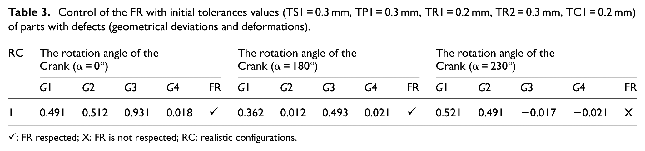
✓: FR respected; X: FR is not respected; RC: realistic configurations.
By using the sub-algorithm of tolerances correction, the initial tolerance value
Control of the FR after tolerances correction (TS1 = 0.3 mm, TP1 = 0.3 mm, TR1 = 0.2 mm, TR2OPT = 0.23 mm, TC1 = 0.2 mm) for each realistic configuration (RC) of the steam engine assembly (after updating the mating constraints between parts with defects).
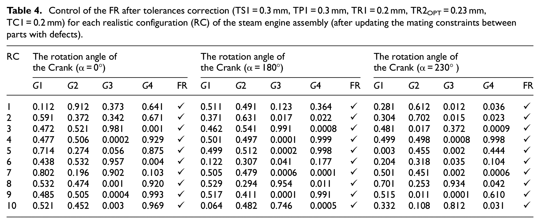
The case study is executed on a PC with Intel Core (TM) i3, CPU 1.80 GHz and 4 GB memories. The last iteration step of tolerance correction (
Consideration of the combined effects of manufacturing defects and deformations in the tolerance analysis process based on the CAD modeling.
Simulation of the realistic mechanism behavior during parts motion.
Conclusion
This paper presents an improved tolerance analysis method of CAD assemblies considering non-rigid joints between parts with manufacturing defects and deformations. The manufacturing defects of rigid components are taken into account based on the worst case method and the SDT parameters. The deformations of non-rigid parts are determined using the FE method. The deformed non-rigid components are reconstructed and inserted in the CAD model. The sub algorithms used to update the mating constraints especially between couples of NR/NR parts are illustrated in order to obtain all realistic configurations of the assembly. The developed method is a decision support tool for engineers and designers during products tolerancing. The model steps are automated and integrated in the CAD software. Nevertheless, the runtime becomes important in the case of high number of parts and specifications. The future works will be focused on the improvement of the developed tolerancing method by reducing the runtime and considering the form defects as well as the contact deformations; in the case of R/NR and NR/NR planar and cylindrical joints.
Footnotes
Acknowledgements
The authors gratefully acknowledge the technical and financial support of Research Center of College of Engineering, Deanship of Scientific Research, King Saud University.
Declaration of conflicting interests
The author(s) declared no potential conflicts of interest with respect to the research, authorship, and/or publication of this article.
Funding
The author(s) received no financial support for the research, authorship, and/or publication of this article.