
Abstract
In manual material handling operations associated with manufacturing, often a two-person team lifts a container. The labor intensive task of lifting a container could be improved by replacing the two-person team with a human-machine team. It is hypothesized that a human-machine team could behave similarly to a two-person team when lifting a container. To test this hypothesis, the presented research experimentally investigated the application of force and position control to a machine that was working collaboratively with a human to lift a constructed container. A basic experimental approach to lifting and control was undertaken at a benchtop scale to evaluate the results for proof-of-concept and further development. For the experimental setup presented, the results show that a combined force and position control architecture delivered better lifting performance as compared to standalone force or position control. It was concluded that the combined force and position control strategy created better team behavior for the machine as it worked collaboratively with the human to lift a constructed container. The advantage of the control approach presented is its simplicity and its ability to be retrofitted to existing equipment. The novelty of the control approach lies within the way the force and position errors from independent controllers are combined into a single command signal with no priority given to either force or position.
Introduction
In material handling operations within manufacturing and construction settings, two-person teams are often used to lift a standardize container and transport it to another location. Each person lifts approximately half the weight and load of the container when grasping opposite ends of the container. The equal sharing of forces is based upon the assumption the container’s weight and load is uniformly distributed and the lifting forces are applied at symmetrically opposite locations on the container. When working as a team, each team member attempts to closely match each other’s motions during the lifting. As one person begins to apply an upward force to their end of the container and displace it upward, the other person simultaneously applies an equal amount of force and displacement to their end of the container. In order to work together to accomplish the task of lifting, the team members must communicate. This communication enables them to coordinate their effort and successfully lift the container. Often the communication consists of the position and force they are sensing regarding the container as well as their intended actions during the lifting operation. An example of this type of task is illustrated in Figure 1.
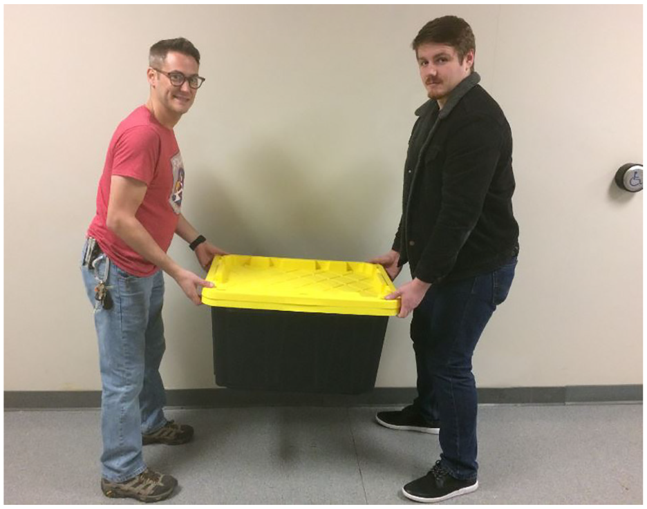
Demonstration of a two-person team lifting a container.
Because a material handling operation can be labor intensive, it could be advantageous to automate the process. Use of automation could reduce labor requirements and be beneficial to manufacturing efficiency. Automation could also be desirable in situations where there is limited labor resources such as remote operating locations. In addition, using an automated machine to perform material handling operations, especially the lifting of a container, reduces the exposure of ergonomic stressors to humans. However, fully automating the handling and transportation of manufacturing containers presents many challenges as presented by Stoyanov et al. 1 The challenges include handling a variety of container shapes, sizes, weights and stacking arrangements while navigating in a manufacturing environment that is dynamic. In essence, a fully automated system must adapt to the numerous variations in containers while operating in an environment that contains obstacles that are changing. The changing obstacles may include people, machinery and other containers.
To address some of the challenges of fully automating a material handing operation, human participation in the operation could be included. This would especially be beneficial when complex decisions have to be made within the manufacturing environment. By having a human and a machine work collaboratively, critical thinking and decisions could be made by the human while the machine assists the human with the physical handling of the container. For example, in the two-person team that lifts a container as described above and shown in Figure 1, one of the team members could be replaced by a machine. By replacing one person with a machine, the labor requirement is reduced. It is hypothesized in this example the human-machine team would work collaboratively to lift the container in a manner that identically matches the behavior of the two-person team. However with the human-machine team, the human would be able to make the complex decisions while the machine provides physical assistant with the lifting of the container. To match as best as possible the behavior of a two-person team, the person would still lift approximately half of the weight and load of the container while the machine lifted the other half.
Literature review
Upon reviewing published literature regarding collaborative human-machine lifting for similar tasks found in manufacturing settings, two general approaches to accomplish the lifting task were found. The first method used a team based approach where the machine and human lifted the object together. The machine and human communicated either through prior teaching or during the operation. When communicating during the operation, each needed to sense the other’s actions as well as the dynamics of the object they were lifting. This approach required the machine or robot to behave like a human. This included being able to sense and anticipate movements. The second method was less sophisticated and involved the robot or machine providing a powered assistance to the human while lifting. The device used could be called a lift-assisting device. With this approach, the human had the overriding control of the lift operation. However, both approaches had similar challenges in regards to dynamics and control.
Works presented by Rahman et al.2,3 addressed human –robot collaboration for manual lifting of objects. For their work they experimentally developed a 1-D power assist robotic system. Their results showed that the inclusion of weight perception in force control strategies lead to better performance and outcomes. They also noted that having input force sensors near the human grasping locations lead to increased performance. Continued work by Rahman and Ikeura 4 developed a control scheme using weight perception as the key element. They were able to demonstrate that the inclusion of weight perception in the control scheme produces optimum human-robot interaction and performance.
Research by Ueno et al. 5 presented the design and development of a prototype robot for lifting heavy loads. The design and control strategy referenced human dynamic motion. Research was undertaken to study the kinematic behavior of humans during lifting and the results were applied to the development of the robot. Their results showed that a dynamic lifting technique where the base joints use greater torques versus the joints closer to where the payload is located is advantageous. This replicated how humans use their leg muscles more to lift an object than their arm muscles.
Rozo et al. 6 presented research that dealt with the physical interaction between humans and robots working as a team. For their work they studied the interaction involved in the transportation of bulk loads in manufacturing plants. Their work focused on teaching the robot the proper path as well as applying the proper force during the interaction with the human. From their effort, they were able to successfully demonstrate an articulating arm robot transporting an object in collaboration with a human. Being able to teach the robot collaborative behaviors from human demonstrations was key to their success.
Another human-robot cooperation study was presented by Roveda et al. 7 It was for industrial applications where the robot provided assistance to the human. Their work identified the need for special safely rules within the controls architecture when cooperative robotic-human tasks are undertaken. They were able to demonstrate a collaborative lifting task with an articulating arm robot. The embedded safety rules limited force and velocity during the interaction while combining an impedance controller for compliant robot behavior. A fuzzy controller was used to assist with the human interaction. Similar research was conducted by Rahman and Ikeura 8 for a power-assist robotic system but focused more on increasing the human-robot interaction and efficiency. Their research presented a variable admittance controller based upon weight perception.
Although not directly related to manufacturing, published research in the area of neuroscience was reviewed that dealt with the human sensing and lifting of objects to better understand how to replicate this process. In particular, research by Hermsdörfer et al. 9 and Polanen and Davere 10 concluded that better results with lifting were supported by either the ability to sense the object prior to lifting or recall from memory the knowledge of a prior lift of the object. Hermsdörfer et al. 9 presented a study in which the human griping force and rate of griping force was confirmed to be scaled to the actual weight of the object. Polanen and Davere 10 investigated the perception of weight and how it is biased from prior lifting experience. They found that the perception of weight was significantly impacted by recent memory of a prior lift. When the perception of weight does not match actual weight, adjustments have to be made in the interaction of motion planning and motor movements. In a recent article by Polanen et al. 11 they investigated the interaction between obtaining sensory information and the responding movements to control an object. Using virtual reality as the experimental platform, their results linked an increase in the weight perception of an object to visual delays.
For complex manipulation of an object, a documented approach to control is a hybrid method in which force and position is controlled simultaneously. An example of a complex manipulation is the grasping and lifting of an object. With this presented example, the hybrid force/position architecture presented by Criag 12 and Railbert and Criag 13 could be applied. Their approach was to divide the controllable degrees-of-freedom (DOF) of the manipulator into a part that was controlled by the position controller and a part that was controlled by the force controller. For instance with the example of grasping and lifting an object, the two translational DOF in a horizontal plane that is parallel to the surface the object is resting on, could be controlled by the force controller. The manipulator could then grasp the object by making positional adjustments within the horizontal plane until the desired contact force is established and maintained. The single translational DOF that is perpendicular to the horizontal plane would be subject to position control. The position controller would be responsible for lifting the object off of its resting surface while the force controller maintained the desired gripping force. A similar but more sophisticated control method was presented by Sijs et al. 14 for use with an assistive robotic manipulator. Their hybrid control method was derived from the way humans guide their hands using forces.
When a robotic manipulator comes into contact with an object or interacts with its environment, the use of force and position control is advantageous.15,16 Gierlak 15 presented a hybrid control model that takes into account that the manipulator is in contact with an flexible environment. With the aid of neural networks the proposed system was demonstrated through simulation to improve control quality. In similar work, Tanner and Kyriakopoulos 16 presented a hybrid controller that utilized both force and position control. The method was based upon a parallel approach that implemented force and position control simultaneously. The controller is unique because it substitutes force derivatives with velocity measurements. In addition the controller partially compensates the position control if there is a desire for an external force.
Successful use of exoskeletons have been demonstrated in lifting operations.17,18 Exoskeletons aid humans with the lifting of heavy object. Since the exoskeletons are wearable devices, overriding control is given to the human. This allows the complex decisions necessary for operation to be made by the human. Research by Chen et al. 17 explored lifting techniques used with an exoskeleton and designed an algorithm that can detect the onset of a lifting movement. Based upon the results, they concluded the detection algorithm could be used to enhance the control of active exoskeletons. With a focus on material handling operations found in industry, work by Yong et al., 18 presented an exoskeleton that had been developed to reduce muscular activity in the human’s back. They conclude further exploration in motor control was needed to make the exoskeleton more applicable for workers in industry who lift and hold heavy objects. Other research regarding the control of lifting devices in industry, emphasized the need for force feedback. Chciuk et al. 19 presented a force feedback system that can be applied in manual control of lifting devices. Their work echoed the need for inclusion of force in the control process.
Presented research
The presented research in this article investigated the basic application of force and position control to a machine that worked collaboratively with a human to lift a container. The experimental setup replicated a lifting task that is similar to what is found in material handling operations in manufacturing environments. Although similar in nature to Rahman et al.,2–4 the presented research in this article experimentally examined fundamental control approaches for a machine lifting a container in conjunction with a human. The research is unique because the experimental setup created a human-machine team that simulated a lifting operation that has historically been performed by a two-person team. With the human-machine team, one of the persons in a two-person team is simply replaced by the machine. It was uniquely desired with the experimental setup for the human and machine to work collaboratively in a manner that replicated the behavior of a two-person team. Hence for the presented setup the weight and load of the container was shared equally by the team members. Half of the weight and load was lifted by the human and the other half was lifted by the machine. In addition, research presented in the reviewed neuroscience articles8,9 was taken into consideration when designing the experimental setup. In particularly the conclusions reached by the authors regarding the importance of being able to sense an object prior to lifting was incorporated into the constructed container. The constructed container for the experimental setup presented in this research was engineered to enhance the sensitivity of force feedback.
For the presented research, force and position control was investigated through experimentation. The experimental setup included a constructed machine and a constructed container. The machine consisted of a 1-dimensional servo system and the container was constructed with input and output sensors for force and position. The machine worked in conjunction with a human to perform a team lift of the container. Force and position control was investigated separately, as well as a combined force and position control architecture.
The constructed servo system lifted one half of the container while a human lifted the other half. The sharing of the lifting setup a team based approach. When force control was investigated, the force applied to the container by the human was used as the input signal to the servo system. Or in other terms, the force applied by the human was the desired output force for the servo system. When position control was investigated, the human lifted one end of the container and the resulting position became the input signal to the servo system and desired output.
The results from the presented work indicated that the combined architecture can be used to create an effective control strategy for the machine in the presented lifting operation. Although the container was able to be lifted with the use of position control, the addition of force control enhanced the performance. The results show the force controller was able to sense the container and apply an equal amount of upward force as the human prior to the upward displacement of the container. Sensing and applying an upward force to the container by the machine prior to upward displacement lead to better team behavior. Better team behavior was observed when the machine was able to more accurately match the motion created by the human.
It was concluded that the combined use of force and position as the controlled parameters of the servo system more accurately replicated human performance in the team lifting task. Thus, the human-machine team behaved more like a two-person team when lifting the container. The presented research has merit in regards to the future development of machines that work in conjunction with humans to perform lifting operations historically found in manufacturing. By sharing the workload and tasks with machines, humans would limit their exposure to hazards in the workplace. In addition, when there are limited labor resources available, such as remote operations at sea or in outer space, humans may have to work together with machines.
The presented research is different from the work discussed in the literature review because the experimental setup is focused on a human-machine team replicating the behavior of a two-person team. All of the reviewed literature presented a machine that did not equally share the load during lifting. In the reviewed literature, the machines lifted most of the load with the goal of eliminating ergonomic stressors on the human. In addition with the presented research, the combined use of force and position control is not the same as the hybrid methods discuss in the literature review. Nor can it be considered admittance or impedance control. 20 The presented research combines the force and position errors into a single command signal with no priority given to the force or position errors. Although control of the system relies on the feedback of position and force, the two signals are independent and do not have a constitutive relation due to the limitations of the experimental setup. Lastly, the results suggest that the force controller primarily contributed to the grasping of the container and preparing the machine for the lifting of the container.
Experimental setup
Physical setup
To conduct the investigation regarding the control of a machine that is lifting a container in conjunction with a human, a small wooden platform with two handles must be constructed to simulate a container. Figure 2 illustrates the constructed container. The platform was 15 cm wide, 37 cm long and 1 cm thick. The container was lifted on each end through the handlebars that were shaped like the letter “T”. Each T-handle was made of rectangular shaped polyvinyl chloride (PVC) bars that were 5 cm wide, 27 cm long, and 3 mm thick. The T-handles were positioned at the two ends of the container approximately 27 cm apart. The total mass of the container was 1581 g and it was uniformly distributed.
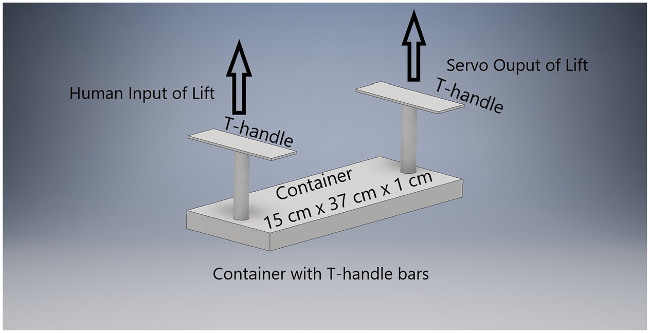
Illustration of the constructed container that was lifted by the human–machine team.
The applied forces and resulting vertical acceleration (

When the container was suspended, an equal amount of its weight was supported between the human and the machine. The weight was equally shared because it was uniformly distributed and the T-handles were positioned symmetrically at opposite ends of the container. The equally sharing of the container’s weight between the human and the machine created a necessary condition for the lifting operation because the machine was to be controlled such that it matched the behavior of the human. In essence, the forces of lifting must be balanced as shown in Eq 2.

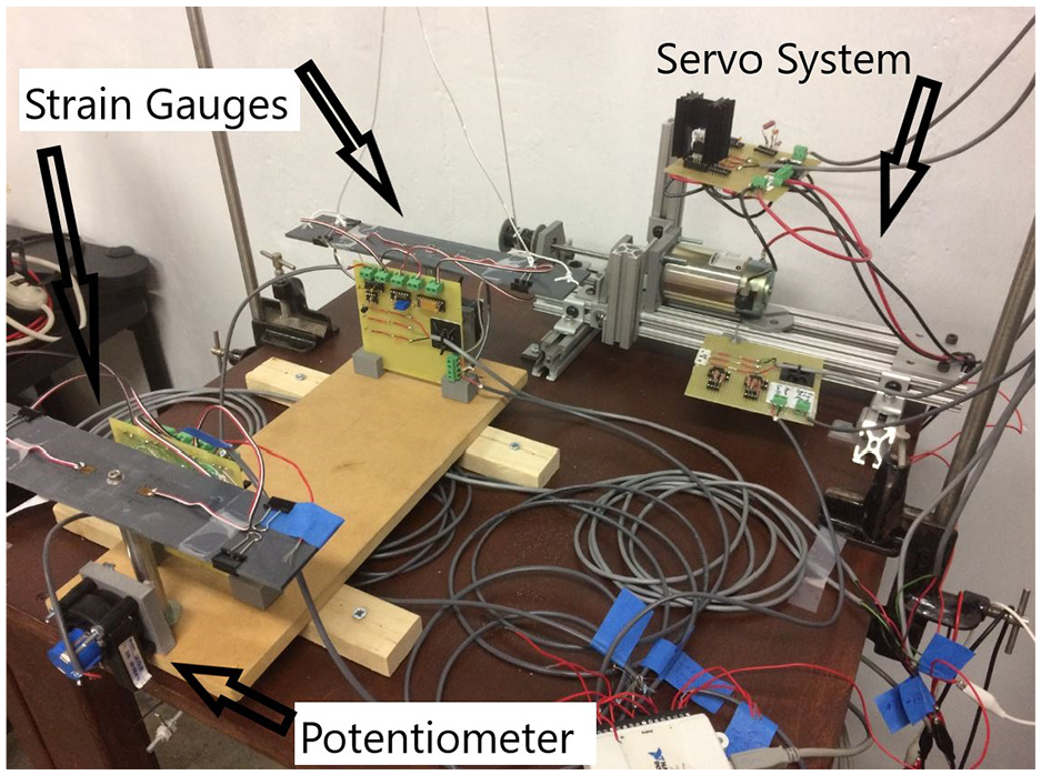
The machine was a constructed servo system that utilized the applied force to the handle bar from the human (FHuman) and the vertical position of that end of the container as the input signals. Using these input signals as reference values, the servo system applied a matching force and lifted its end of the container to the same vertical position. The mechanical components of the servo system consisted of a small D.C. motor that was reversible in direction, an output shaft & spool, and a lightweight cable-pulley system. The D.C. motor was a Pittman Express face-mounted motor (model number 14203S010) that was rated for 12 V and had a torque constant of 4.63 N-m/A. The D.C. motor was mounted to a frame made of commercially-available aluminum extrusions. The electrical components of the servo system consisted of an amplifier circuit and the sensors used to measure the input and output values of force and position. The servo amplifier circuit was designed and fabricated to receive a processed control signal within a range of ±5 V and provide a current of ±5 A to the motor. This was accomplished using various resistors, an LF412 op-amp, a TIP120 Darlington transistor and a TIP125 Darlington transistor. Figure 3 shows the experimental setup with a view of the servo system and one end of the container with its T-shaped handle bars.
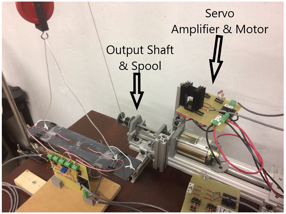
View of the servo system and one end of the container with T-shaped handlebars.
The motor’s shaft was coupled to a 6.35 mm diameter output shaft that was 152.4 mm in length. The output shaft was supported by two commercially available 6.35 mm ball bearings. The ball bearings were mounted inside 3-D printed pillow blocks that were bolted to the same frame as the motor. Mounted to the output shaft was a 3-D printed spool. The spool’s function was to feed and retract a nylon cable through the pulley system. The nylon cable was used to apply a force and lift one end of the container. The cable-pulley system was suspended above one of the T-handle and had a mechanical advantage of 6:1. With one end of the cable firmly wrapped around the spool and threaded through the pulley system, the other end was attached to the T-handle of the container. Figures 4 and 5 are additional pictures of the experimental setup.
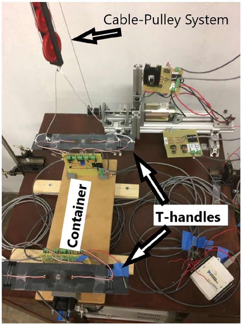
View from above of the constructed container and the servo system.
Isometric view of the experimental setup.
Figure 6 shows a demonstration of the experiment in which a human and the servo system are working as a team to lift the container. Since the research was experimental in nature, the container and servo system were created at a benchtop scale. Notice in Figure 6 that the servo system has lifted its end of the container a similar amount as the human.
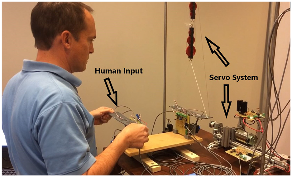
Demonstration of the experimental team lifting operation.
At each end of the container was a UniMeasure LX-PA-50 string potentiometer with 10 V applied to the input terminal. Near the center of each T-handle was 4–350 ohm strain gauges. These strain gauges were arranged in a Wheatstone Bridge configuration and used to measure the force being applied to each T-handle. The input voltage to the bridge was 10 V and an AD624 instrumentation amplifier was used to apply a gain of 500 to the output voltage. Once the strain gauges were mounted and integrated into the circuitry, each were calibrated by applying a series of known loads of force to the handle bars and recording the output electric potential (voltage). Similarly the potentiometers were calibrated by lifting each end of the container to known positions and recording the output electric potential (voltage). All calibration data showed linear relationships with the respective output electric potentials (voltages).
As can been seen in Figure 6, the upward force applied to the T-handles was applied at the outermost edges. By applying the lifting force at the outer edge, a significant bending moment was induced at the center of the T-handle. In addition, deflection of the T-handle was clearly visible. The bending moment and resulting strain in the T-handle were maximized near the location of the strain gauges. It was noted during the calibration of the strain gauges that loads applied to the handle as small as 2 g (0.02 N) could be detected. This sensitivity allowed the servo system to react to very small amounts of force. The key enabler for the sensitivity was the PVC. This is why PVC was selected as the material for the T-handles instead of a material such as steel. The PVC handlebars had a relatively low flexural modulus of approximately 2.9 × 10⁹ Pa. The low flexural modulus allowed the T-handles to easily deflect under the application of a lifting force. The amount of applied force directly correlated with the strain of the handlebars which was measured through strain gauges. The net result was an environment that was sensitive to an applied force.
MatLAB – Simulink was used as the tool for programing and integration of the system. With this software, a controls architecture was setup for signal processing and commands. Along with Simulink, a National Instruments USB-6009 data acquisition device was used to acquire signals from the strain gauges and potentiometers as well as send control signals to the servo amplifier. The feedback of force was achieved through the strain gauges attached to the T-handles the servo system lifted. The feedback of position was achieved via the potentiometer mounted to the container on the end the servo system lifted. Similarly the input signal for force was received from the strain gauges on the T-handle the human lifted and the position signal was from the nearby potentiometer. Figure 7 provides a block diagram of the control architecture used for this experiment while the control law used is presented in Equation 3.
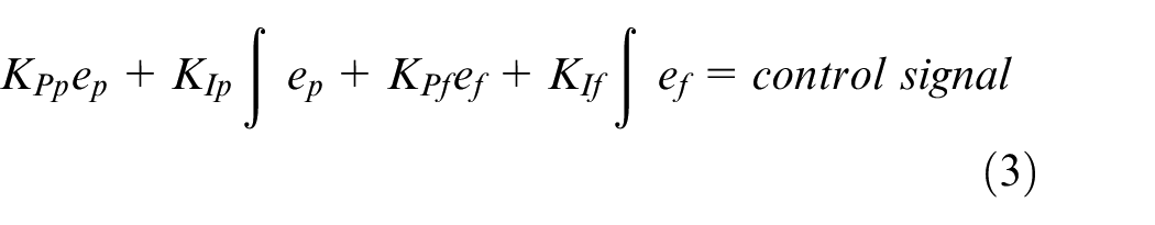
As can be seen in Figure 7, the inputs of force and position by the human are used as the reference points and desired outputs. Because the instruments were electrical in nature, the force and position signals were measured in electrical potential (voltage). The difference in the actual output of force by the servo and the input provided by the human was the force error (ef). The difference in the actual output of position by the servo and the input provided by the human was the position error (ep). With the control law expressed in equation (3), the error in position (ep) was multiplied by a proportional gain constant (KPp); plus it was integrated and multiplied by an integral gain constant (KIp). Similarly, error in force (ef) was multiplied by a proportional gain constant (KPf); plus it was integrated and multiplied by an integral gain constant (KIf). After processing the two error signals with the proportional and integral methods, the signals were combined into a control signal that was sent to the servo amplifier circuitry. The servo amplifier converted the electrical potential (voltage) of the control signal to a supplied current for the D.C. motor. The servo amplifier had a gain of 1 A/V.
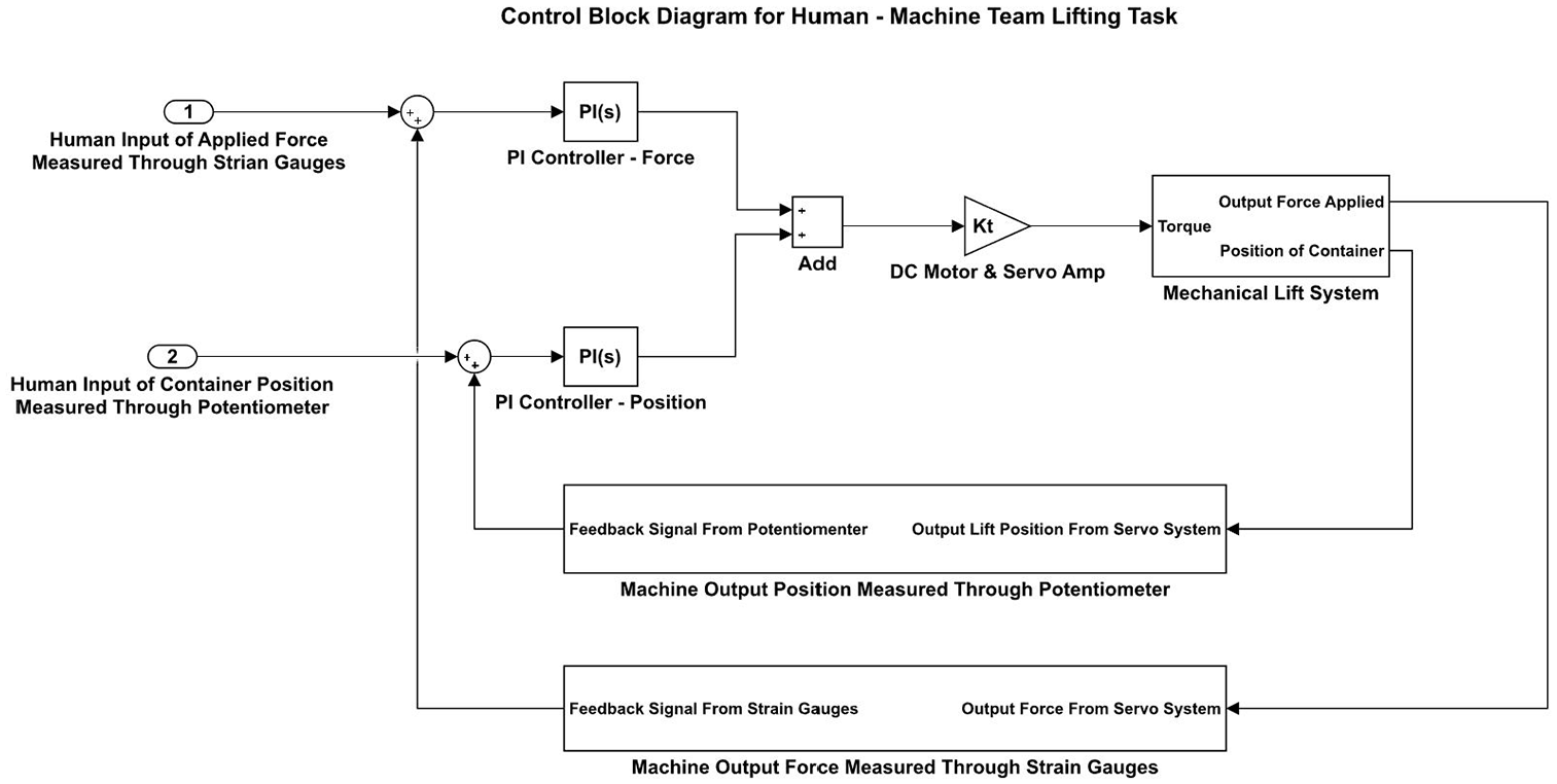
Block diagram of the control architecture.
With a current supplied to the D.C motor, a proportional amount of torque (torque constant) was delivered to the output shaft of the motor. As noted prior, the torque constant was 4.63 N-m/A. Once the mechanical torque from the motor was applied to the spool, it could be rotated to either feed or retract the cable through the pulley system. With the other end of the cable attached to the container, the resulting upward motion of the cable would apply a force to the T-handle and lift the container upward. Once tension had been established in the cable, the force could be lowered by turning the spool in the opposite direction.
Three different approaches to control were investigated. For the first approach, the system was setup so that force control could be studied alone as the only controlling variable. This was simply done by using an internal switch in Simulink which made all the position control gains zero. In the second approach, the experiment was configured such that position control could be studied alone. For this scenario all the force control gains were set to zero. Lastly the experiment was setup to investigate the simultaneous application of force and position control. This approach is fully illustrated in the block diagram of Figure 7 and equation (3).
Both the force controller and the position controller were tuned independently using the Ziegler-Nichols tuning method. 21 Upon tuning the controllers it was discovered that both the force and position control loops responded best under proportional (P), and proportional & integral (PI) control. This was comprehended in the control law of equation (3). For proportional control the error signal was simply multiplied by a proportional gain constant. PI control was achieved by multiplying the error signal by a proportional gain constant while simultaneously integrating the error signal and multiplying it by a constant integral gain. Lastly for PI control, the processed error signals were added together to produce a control signal. Derivative control was tried, but due to electrical noise from the strain gauges and the potentiometer, it was not instituted for the research study. To aid in reducing electrical noise, the input and feedback signals of both force and position were rounded to an appropriate level so as to adequately reduce electrical noise but not significantly reduce the accuracy and responsiveness of the system.
The assumptions for the experimental setup include: no deflection of the cable-pulley system, no stretching of the cable, a balanced load within the container, equal sharing of the load between the human and the machine, and the setup can be scaled to a larger system.
Simulation model
A model of the container and its control system was constructed and simulated using MatLAB-Simulink. The simulation provided a prediction of the system’s behavior and allowed for comparison to the experimental results. Figure 8 presents the block diagram of the system modeled. Upon review of Figure 8, it can be seen that the combined use of force and position control was identical to the experimental setup presented in Figure 7. The same condition regarding the equal sharing of the load presented in the experimental setup was also applied to the model. In addition, the controllers in the model were tuned using the Zeigler–Nichols method. 21
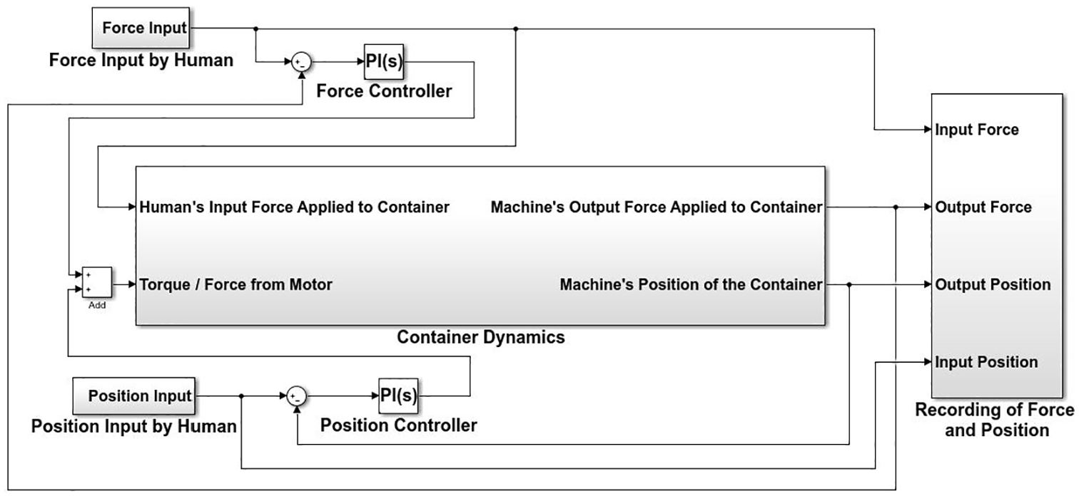
Simulink model.
The container dynamics alluded to in Figure 8 are based upon equation (1) presented in section 2.1. However, the container’s T-handle used by the machine for lifting was further modeled to predict the force (Fmachine) acting on the container by the machine. To determine the force Fmachine, a similar force control modeling technique presented by Criag 12 was used.
The T-handles were two cantilever beams mounted back-to-back. Each T-handle behaved in a manner identical to a mechanical spring such that a proportional amount of spring force resulted as the ends of the T-handle deflected. The lifting force was applied to the ends of the T-handle (cantilever beam). As can be observed in Figures 2 through 6, the T-handles were the connection point between the lifting cable of the machine and main body of the container. Thus, the spring force within the T-handle (Fspring) was considered to be the force applied by the machine (Fmachine). See equation (4). This approach assumed a quasi-static situation were any damping or disturbance force was ignored in the determination of the force applied by the machine.

A model of the containers main body and one T-handle is presented in Figure 9. From this model, equation (5) was used to predict the dynamics of the T-handle.

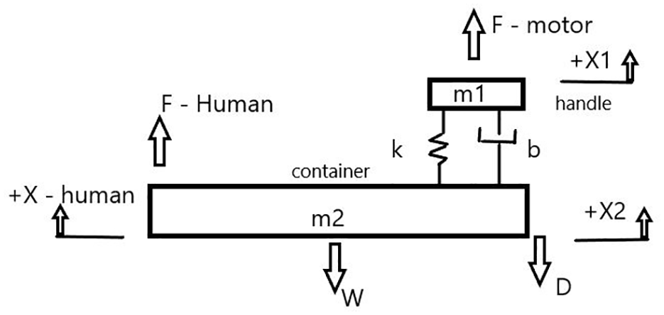
Model of a T-handle and the container’s main body.
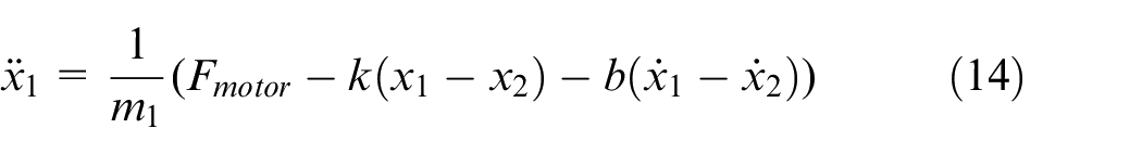
The force Fmotor represents the output force of the motor, k represents the spring constant of the T-handle and b represents the viscus damping coefficient within the T-handle (cantilever beam). The summantion of the forces on the left side of the equation results in the net force acting on the handle. Lastly in equation (5), the mass of the handle is represented by m1 and the position of the handle is represented by x1. The spring force (Fspring) discussed previously is described by equation (6) and is present within equation (5). As stated in equation (6), the force was proportional to the vertical displacement of the T-handle relative to the container’s main body.

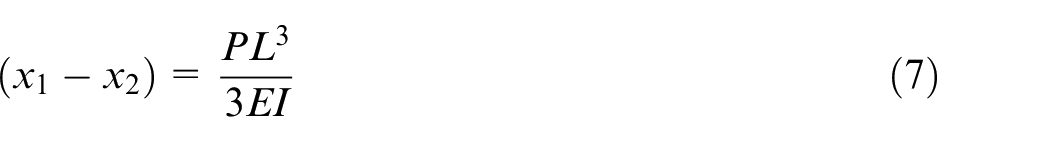
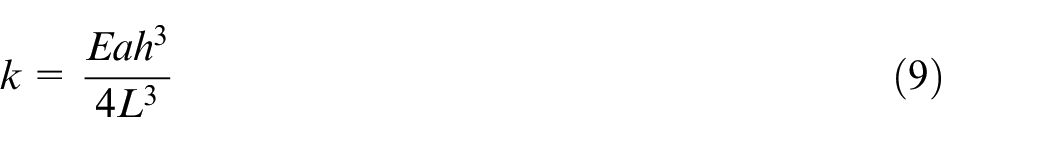
Since each T-handle was two cantilever beams mounted back-to-back, equation (7) describes the relationship between an applied load (P) and the resulting deflection (x1–x2). 22 In equation (7), (L) represents the length of the cantilever beam, (E) represents modulus of elasticity, and (I) represents the second moment of the cross sectional area of the beam. Rearranging equation (7) into the form of equation (6), results in the identification of the spring constant (k). See equations (8) and (9). In equation (9), the second moment of area is expressed in terms of the beam’s width (a) and height (h). Since the T-handle consists of two cantilever beams, the resulting spring constant (k) in equation (9) must be doubled.

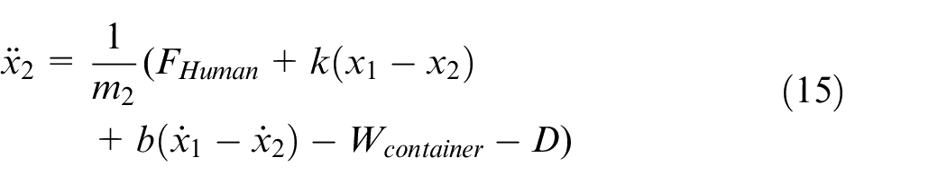
From the model in Figure 5, the dynamics of the container’s main body was predicted with equation (10). In equation (10), FHuman is the input lifting force applied by the human, Wcontainer is weight of the container, D is a damping force, m2 is the mass of the container and x2 is the position of the container. For model simplicity, the damping force was considered viscus.
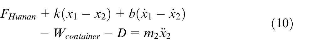
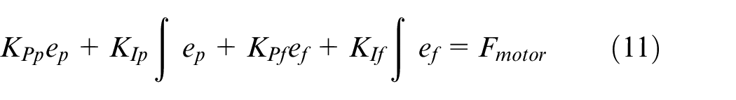
To predict the container’s position, equation (10) was solved for the container’s upward acceleration and then integrated twice using Simulink. Similarly to predict the T-handle’s position, equation (5) was solved for the handle’s acceleration and then integrated twice using Simulink. Lastly the control law presented by equation (3), provided the output force of the motor (Fmotor) as described in equation (11).
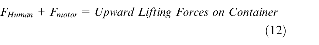
For clarity and greater insight, the dynamics can be summarized with the following description. The lifting of the container is due to the applied lifting forces. This is expressed by equation (12) and shown in Figures 8 and 9.
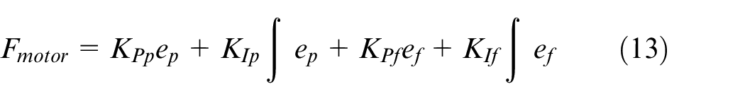
The lifting force from the motor is governed by the control law of equation (3) but restated in the form of equation (13). Notice the control law combines both the position and force errors into a single control signal. This is illustrated in Figure 8. The inputs to the control system are the lifting force applied by the human and the position of one end of the container.
The force from the motor is applied to the T-handle and the position of the T-handle is predicted by integrating equation (14) twice within Simulink. This is illustrated in Figure 9.
The force provided by the human is applied to the container’s body along with the reactive forces within the T-handle connected to the motor, the container’s weight and the system’s damping force. The output position of the container is predicted by integrating equation (15) twice within Simulink. This is illustrated in Figure 9.
Lastly the output force applied by the machine is predicted by equation (16) which results from the combining of equations (4) and (6).

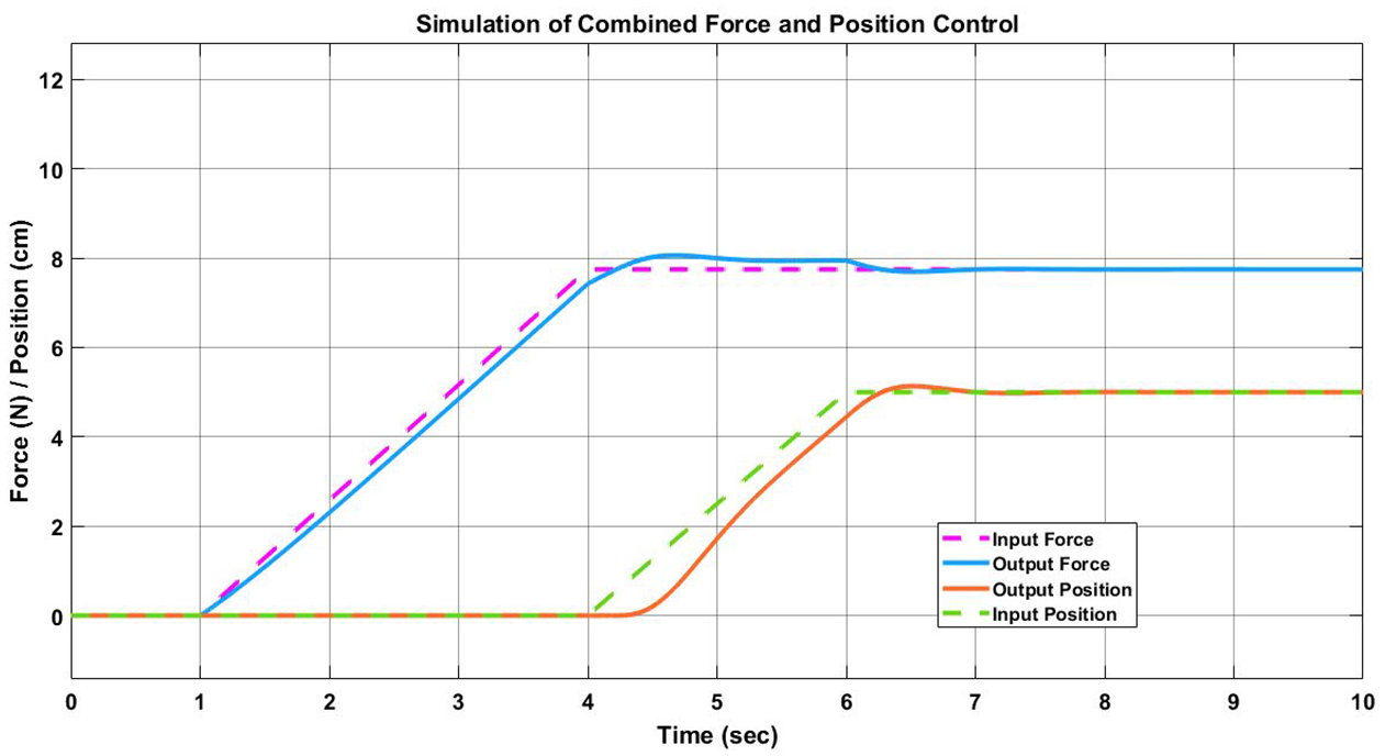
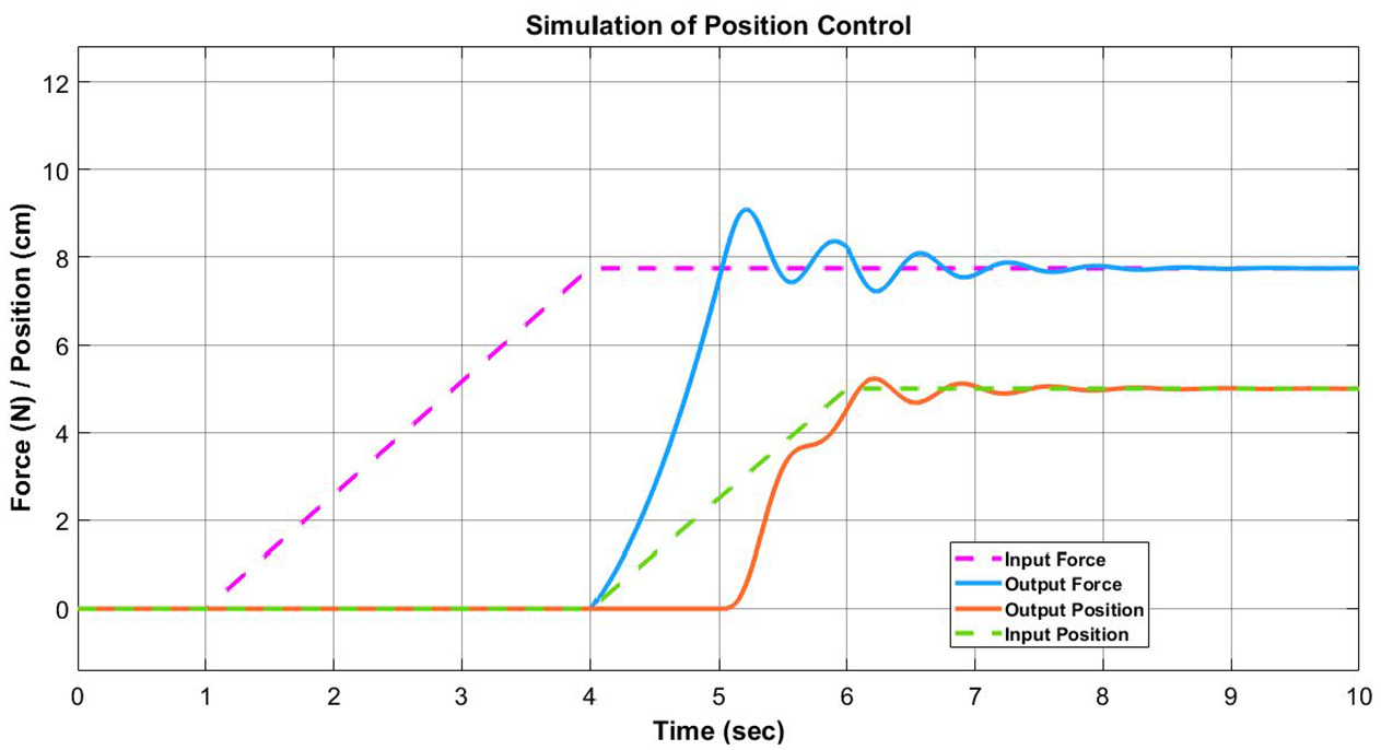
The results of the simulation of combined force and position control is shown in Figure 10. The results predicted that if smooth and steady input motion is provided by the human, the machine will behave in a controllable manner and work in conjunction with the human to lift the container. Smooth and steady motion was modeled with the ramp inputs of force and position. The maximum value of the input force was selected as half of the weight of the container. This allowed for the equal sharing of the load as described in the experimental setup. Upon close inspection of Figure 10, a 0.5 s lag in response to the control of the container’s position was predicted. A likely contributing factor to this lag was the elastic behavior of the T-handles. This behavior became problematic when a step input was simulated.
Simulation results. Upper data pair is force.
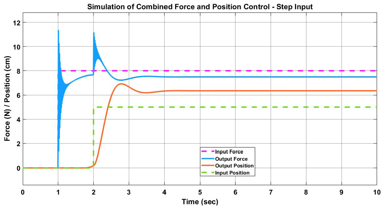
Figure 11 shows the predicted response to step inputs. The need for smooth and steady input motion is illustrated in Figure 11. As can been seen in Figure 11, large errors in force and position can lead to a situation where the force and position control responses oppose each other. The force response required an increase in output but the position response required a decrease. However, smooth and steady lifting motion is characteristic of good lifting technique that promotes safety and ergonomics and should be desired.
Simulation results in response to step inputs. Upper data pair is force.
Figure 12 presents the predicted response to lifting while under position control only. When comparing this response to the combined force and position control response of Figure 10, differences are noticeable. Specifically there is a larger lag in response to the upward motion of the container. As can be viewed in Figure 12, there was approximately a 1.3 s delay between the input and output position. In addition, larger errors in position are predicted and it takes several seconds before the errors are eliminated.
Simulation results of position control. Lower data pair is position.
For the simulation, all model variables were either calculated or measured except for the two damping forces which were estimated. The source of the damping associated with the T-handle in equation (5) comes from internal friction. The source of the damping present in equation (10) comes from the lifting mechanism and the T-handle held by the human. The lifting mechanism consists of the D.C. motor, the output shaft and the cable-pulley system. Lastly it should be noted that the sensors, cable-pulley system and the D.C. motor of the experimental setup were not included in the model. However, the results of the simulation approximately matched the experimental results presented and observations discussed in the following section. Thus there was a reasonable level of confidence in the simulation model.
Results and discussion
Force control results
While testing the system under force control, the position control loop within the architecture presented in the block diagram of Figure 7 was turned off. This isolated the response to force only. Under P control the system responded very quickly to a step input. The step input was created by placing a known load on the handle where the human would normally grasp and activating the controller. However, there was a significant steady state error in the result. The source of the error most likely resided in the elasticity & friction of the cable & pulley system as well as the elasticity in the T-handles. The processed error signal and subsequent control signal did not produce a strong enough torque from the D.C. motor to overcome this steady state error.
To address the steady state error, PI control was implemented. The results were much better because the steady state error was eliminated. However, an overshoot in force did occur as can be seen in Figure 13. As with all the figures presented in the results section, the data shown in Figure 13 is a sample that is representative of many trials. Subsequent testing determined the amount of overshoot was related to the amount of slack in the cable prior to the activation of the controller. If there was slack, the system first had to wrap the loose cable around the spool until the cable was taut throughout before a force could be measured by the strain gauges. It was noted that excessive slack could create instability issues. However, as long as the slack in the cable was minimum, the system response was acceptable.
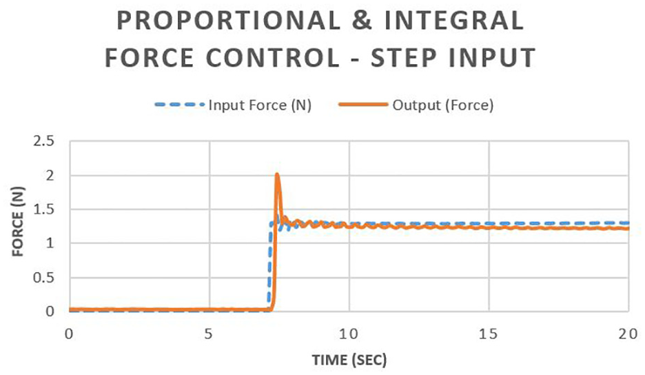
Sample data of PI force control response to a step input.
Under PI control, lifting of the container was attempted many times. For this part of the experiment, the force applied to the container by the human was used as the input force to servo system. To begin, the human grasped the handles and gradually applied a force. Next the human lifted their end of the container. The other end of the container was lifted by the servo system. A sample of the results can be seen in Figure 14. Although the system was under force control, measurements of the container’s position were recorded. In Figure 14, the input position of the container refers to the end the human is lifting while the output position refers to the end the servo system is lifting.
Sample data set of lifting of the container under PI force control. Upper data pair is force.
Under force control, the servo system did not lift the container adequately. Although the controller responded as commanded, the applied force from the servo did not position the container correctly. As can be seen in Figure 14 with the position data, the human initially lifted one end of the container but the servo did not lift its end. Only after the human lowered and the raised their end of the container for a second time, did the servo response with lifting. It appears from the data that the strain gauges could not reliably sense the dynamic force associated with movement.
While under force control, it was observed that the strain gauges could detect force associated with the human grasping the handles prior to lifting. During the grasping of the handles, a lifting force was gradually applied upward prior to the container beginning its upward motion. This sensitivity was evident in the fact the servo system was able to detect a grasping force from the human and begin to apply a matching grasping force. Evidence of this behavior is seen in Figure 14 with the force data. Notice how the servo system while under force control responded to force prior to the container moving upward. This replicating behavior from the servo system immediately signaled to the human that the machine was operating in tandem and preparing to lift the container as a team. Although nonverbal, this response served as an important communication method to the human.
Position control results
Similar results were observed when testing the system under position control. While under position control, the force controller was turned off so the response was isolated to position only. To evaluate the system’s performance under position control, a step input was used. The step input was created by resting the input end of the container on a riser while the output end remained at a lower height. The input measurement of position and the position controller was turned off initially and then switched on to create a step input.
Under P control the system responded with overshoot and a significant steady state error. Under PI control the steady state error was eliminated as can be seen in Figure 15. In both P and PI control, a noticeable disturbance occurred to the input measurement of position during the response of the servo system to the step input. The source of the disturbance was believed to be the physical movement of the container and the associated electrical noise. The output response of the servo system with its movement to its end of the container possibly created disturbances to the input measurements at the other end of the container. Disturbance to the input measurements would have been processed into the control signal for the servo system and thus most likely further compounded the disturbance. Hence, some of the overshoot in the response observed in Figure 15, could be due to the input signal disturbance. In addition, surge in the electrical current when the controller was turned on at the time of the step input could have contributed to the disturbance.
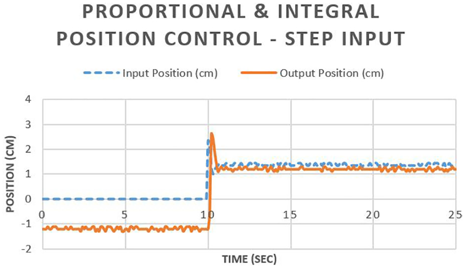
Sample data of PI position control response to a step input.
Under PI control, lifting of the container was attempted many times. The position of the end of the container lifted by the human was used as the input position to the servo system operating under position control. A sample set of the results are shown in Figure 16. Although the system is under position control, measurements of the force applied to the container’s handles were recorded. The input force refers to the lifting force the human was applying to its handle, while the output force refers to the lifting force the servo system was applying.
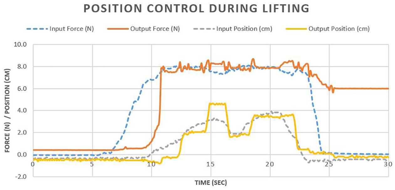
Sample data set of the lifting of the container under PI position control. Lower data pair is position.
The overall response under position control to lifting was much better than the response under force control. The servo system did lift its end of the container as required but some positioning errors are noticed in Figure 16. The overshoot in response near the middle of the lift can be attributed to the integration of error in the PI controller. It also can be seen from the force data in Figure 16 that the human began applying a lifting force approximately 3–4 s before the servo system responded since it was in position control. This lag in response may have contributed to some of the initial positioning errors were the human was lifting its end of the container while the servo system was preparing to lift the container. During this time of preparation, the servo system was removing slack in the cable and responding to the elasticity in the mechanical components. This elastic behavior can be seen in the steady increase in output force near the 10 s time period. During this application of the output force, the output position of the container did not increase. Thus, likely indicating a delayed response due to the elasticity. During the second half of the lift in the 16–25 s range, the response was much better as can been seen in Figure 16. This improved response is most likely from the controller adjusting to the elastic environment and the initial delay.
The lag in response while under position control was also present in the simulation results. As can be seen in Figure 12, the simulation model predicted approximately 1.3 s of lag in response to the upward displacement of the container. Similarly as can be seen in Figure 16 with the experimental results, approximately 2.3 s of lag in the response was present. However, the system of the experimental setup remained stable but a notable amount of error was present through most of the lifting. A key difference between the experimental setup and the simulation was the force sensing was limited to static loading in the experimental setup. In contrast in the simulation, the output force is calculated with no practical limits. Thus with the experimental setup, the feedback of force was limited to approximately half the weight of the container. Another key difference was the simulation did not include any modeling of the cable-pulley system or the D.C. motor. The only exception is an estimated damping force acting on the container. The further delay and additional positional errors observed in the experimental results may be attributed to the performance of the D.C. motor and the cable-pulley system.
Combined force-position control results
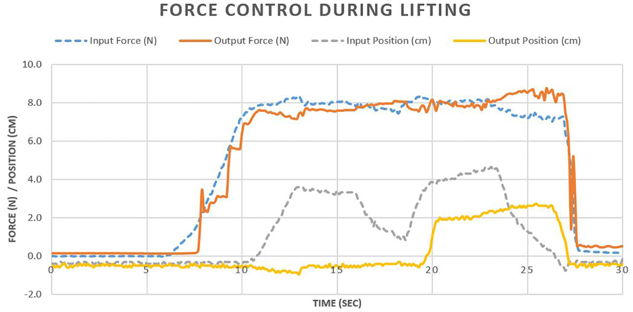
The results of a combined force-position control architecture showed the response of the servo system to be improved as compared to either force or position control by itself. A sample data set of the results is shown in Figure 17. Overall, the servo system tracked the input relatively well. In particular, the output position was tracked to the input position with much better accuracy. This was likely due to the force control aspect of the system applying a pre-lifting force along with the human.
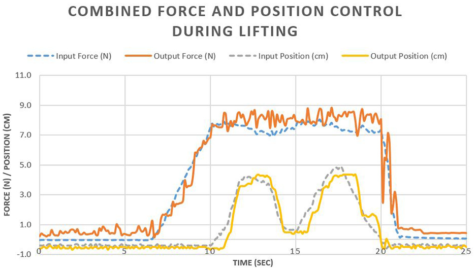
Sample data set of combined force and position control during lifting. Upper data pair is force.
Upon comparing Figures 16 and 17, it can been seen how the force was controlled in Figure 17 and not in Figure 16. When controlling force, the servo system simultaneously applied an upward lifting force before the container was actually moved upward. From the human’s perspective, the input force prior to the upward motion of the container was a time when the human was sensing the load and preparing to lift the container. This sensing and preparation contributed to efficient lifting by the human. Based upon the results, the servo system appears to have experienced a similar phenomenon. As seen in Figure 16, without force control the servo system had difficulty achieving the desired lift position. Only after several seconds did the servo system begin to achieve relatively accurate tracking of the input position. Upon comparing this response to that shown of Figure 17, it can been seen that greater accuracy was achieved in the tracking of the lift position when the servo system had applied a pre-lifting force along with the human.
As noted earlier with the pure force control response, the replicating behavior from the servo system prior to lifting the container provided important communication to the human. This type of communication is needed in a team lifting operation. The feedback to the human that the machine was operating in tandem and preparing to lift the container as a team, provided confidence to the human that a successful lift was about to occur. Furthermore, equal sharing of the lifting operation between the human and the servo system can be observed in Figures 16 and 17. Both the maximum input and output force was approximately 8.0 N. When comparing it to the weight of the container (1581 g, 15.5 N), it appears that the weight of the container was equally lifted by the human and the servo system.
Lastly, an increase in fluctuations of the output force can been seen in Figure 17. As noted earlier with the elastic T-handles, the mounted strain gauges were very sensitive to force and deflection. It was believed the combined force and position error created a stronger control signal and lead to fluctuations in the deflection of the T-handles. This was the only disadvantage observed with the combined use of force and position control. As discussed in the experimental setup, the force controller was tuned independently of the position controller. This separation in the tuning of the controllers most likely contributed to the strong output signal and subsequent fluctuations. However, the fluctuations did not prevent the system from preforming adequately.
It was also noted that because of the unique setup were the human and machine worked as a team to lift the container, the output of lifting from the machine affected input measurements of force and position with disturbances. Likewise, input lifting by the human affected output measurements of the servo system. This was particularly true for the force measurements. Regardless, this phenomena did not greatly degrade the performance of the servo system or inhibit the lifting operation. However, it did at times produce motion of the container that was not completely smooth and steady. The motion could be described as choppy or jerky. It was reduced or eliminated by the human by reducing the speed and acceleration of their lifting motion.
Upon comparison of the experimental results presented Figure 17 to the simulation results presented in Figure 10, a close correlation can be observed. Nether set of results had significant errors in force or position. Most notably, as observed in Figures 10 and 17, the lag in position response was drastically reduced as compared to the response under position control only. In addition, there was observable improvement with the position accuracy throughout the lifting motion in both the simulation and experimental results. As can be observed in Figure 17, approximately 1 s of delay occurred between the input displacement of the container by the human and the output displacement by machine. In comparison, the simulation predicated approximately a 0.5 s lag in response.
However, as discussed prior and observed in Figure 11, the simulation predicted the need for smooth and steady input motion. Without steady input motion, large errors in force and position could emerge. The force response required could be conflicting with what is required for the position response. These opposing responses could lead to significant steady-state error in both position and force. Some of the force fluctuations along with the choppy or jerky motion observed with the experimental setup, could be attributed to the momentary situations where the controller was sending signals that created conflicting responses. However, as observed in the experimental results, no issues with controllability were observed for as long as the input motion was steady and smooth. Lastly it can be noted that the simulation predicted small oscillations in the output force. Based upon this prediction, part of the force fluctuations observed in the Figure 17 could also be attributed to the elasticity of the handle.
Conclusions
Based up the results from the presented investigation regarding a human – machine team lifting a container, it was concluded that the combined force and position control method has advantages as compared to either a standalone force or position control method. The use of force control along with position control, enabled the servo system to apply an output force to the container prior to the motion of the container. Application of the output force to the T-handle prior to the lifting motion enabled the servo system to behave similarly as to how the human applied force to the handles. This matching behavior between the human and the machine created a more team-like approach to lifting. The combined use of force and position control also resulted in increased accuracy in the positioning of the container as compared to standalone position control. This increase in accuracy was predicted in the simulation model, as well as observed in the results of the experimental setup. In both the simulation and the experimental results it appears the force controller was able to address the elastic behavior of the T-handles prior to the upward motion of the container. The application of the force to the container prepared the servo system for the pending upward lifting motion thereby matching the input from the human. The novelty of the
The disadvantage of combining force and position control is the controllers may oppose each other. This was evident in the simulation when large errors in force and position were present. In addition and based upon observations during the experimental testing, choppy and jerky output motion was observed at elevated speeds. This was accompanied by fluctuations in the output force. Along with the observations, results from the simulation model indicated the need for smooth and steady input motion. However for lifting operations in a manufacturing environment, smooth and steady motion is desirable to avoid injury.
To address the disadvantages of the combined use of force and position control, a switching control scheme could be utilized. Since the force controller was most effective at the beginning of the lift, the force controller could be turned off once the container begins its upward motion. During standalone testing, the force controller was highly effective with replicating the human’s grasping, compensating for the elastic behavior of the T-handles, and preparing the system to lift the container. However, it was not effective with positioning the container during the actual lift. By turning off the force controller once the container has been displaced off its resting surface, fluctuations due to the sensitivity of the strain gauges would be eliminated. In addition, since the elasticity in the T-handles would have been addressed prior, the position controller would be able to position the container to the same level of accuracy as a combined force and position controller.
Lastly, the presented research was demonstrated at the benchtop scale and served as a proof-of-concept model that focused on the lifting of a manufacturing container. Future work can be done by creating a larger model that lifts containers of different sizes, shapes, and of heavier weights. A larger model would allow for more practical applications to be studied. With a larger model and a desire to make it implementable to a wide range of manufacturing scenarios, the potentiometers should be eliminated and replaced by single tilt sensor that senses if one side of the container is not level with the other. In addition, the tilt sensor should be made portable and wireless so it can be placed on any container. The system can also be more applicable by eliminating the force sensors in the handles. For the output force, it could be measured through the current supplied to the DC motor since the current is directly proportional to the torque. The input force could be obtained through the development of a wearable force sensor for the human.
After the development of a larger model, this team-lifting control technology would then need to be implemented on articulating robots and other automated machines. The advantage of the control approach presented is its simplicity and its ability to be retrofitted to existing equipment. The novelty of the control approach lies within the way the force and position errors from independent controllers are combined into a single command signal with no priority given to either force or position. This novel approach to control reduces the cost barrier for implementation with the reuse of existing equipment and provides a more sustainable approach for manufacturing companies. For retrofitting, the sensors would need to be added along with a closed-loop force controller. The force control loop is parallel to the position control loop and would remain outside of an existing position control loop as illustrated in Figures 7 and 8. As compared to the research discussed in the Literature Review, the presented research provides a streamlined approach to control. In principle, while the presented research focuses on the control method, much more work would need to be done on the implementation of this technology onto hardware such as wearable force sensors.
Footnotes
Appendix
Declaration of conflicting interests
The author(s) declared no potential conflicts of interest with respect to the research, authorship, and/or publication of this article.
Funding
The author(s) disclosed receipt of the following financial support for the research, authorship, and/or publication of this article: Tennessee Space Grant Consortium
Code availability
Available upon request.
Availability of data material
Available upon request.