
Abstract
During machining, it is well-known that unstable self-excited vibrations known as regenerative chatter can limit productivity. There has been a great deal of research that has sought to understand regenerative chatter, and to avoid it through modifications to the machining process. One promising approach is the use of variable helix tools. Here, the time delay between successive tooth passes is intentionally modified, in order to improve the boundary of instability. Previous research has predicted that such tools can offer significant performance improvements whereby islands of instability occur in the stability lobe diagram. By avoiding these islands, it is possible to avoid regenerative chatter, at depths of cut that are orders of magnitude higher than for traditional tools. However, to the authors’ knowledge, these predictions have not been experimentally validated, and there is limited understanding of the parameters that can give rise to these improvements. The present study seeks to address this shortfall. A recent approach to analysing regenerative chatter stability is modified, and its numerical convergence is shown to outperform alternative methods. It is then shown that islands of instability only emerge at relatively high levels of structural damping, and that they are particularly susceptible to model convergence effects. The model predictions are validated against detailed experimental data that uses a specially designed configuration to minimise experimental error. To the authors’ knowledge, this provides the first experimentally validated study of unstable islands in variable helix milling, whilst also demonstrating the importance of structural damping and numerical convergence on the prediction accuracy.
Introduction
During machining, unstable self-excited vibrations can be caused by the regeneration of surface waves on the machined workpiece. Pioneering work 1 described the concept of the stability lobe diagram, which illustrates the boundary of stability on the spindle-speed versus width of cut plane for turning operations on a lathe. More recent studies have extended this analysis to provide a rigorous framework for considering the case of milling, 2 where the periodic forcing of the rotating tool creates additional complexities.
In general, chatter research has focussed on two aspects: avoidance of chatter by modifications to the system, or improved modelling to better understand the cause of the instability. For the case of modifications, a wide variety of concepts have been studied, such as the use of passive, semi-active, or active damping,3–5 on-line or continuous variation of the spindle speed,6,7 and the use of variable pitch tools. 8 In the last case, the stability boundary is modified because the unequal spacing between successive teeth changes the time delay within the system as illustrated in Figure 1(b). Variable helix tools are an extension to this concept, whereby the time delay between consecutive teeth varies along the axis of the cutting tool as shown in Figure 1(c).
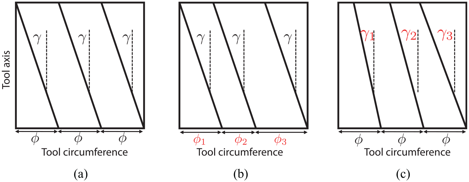
Schematic representation of the flutes around the circumference of a milling tool. (a) Regular milling tool, (b) variable pitch milling tool, where the spacing
Meanwhile, improved models of machining chatter have focussed in particular on the role of periodic excitation of the system for the case of milling. Here, the periodic motion of the tool leads to time-periodic coefficients within the delay-differential equation. Merdol and Altintas 9 incorporated this by considering a Fourier series expansion of the periodic terms. Mann proposed an alternative approach based on Time-Finite-Element-Analysis, 10 and Insperger et al.11–13 developed the semi-discretisation method. An alternative approach, that is related to the semi-discretisation method, is Chebyshev collocation. 14 Like the semi-discretisation method, this implements a time domain discretisation of the dynamic equation of motion. Recent work has also considered its application to variable helix tool geomeries. 15
The present article focusses on the special case of variable helix tools. A literature review will first show that there has been limited work to experimentally validate the stability of these tools, focussing on the regions where islands of instability occur. The paper then aims to address this shortfall, while also demonstrating the requirements for the onset of such islands, in terms of the dynamics of the machining structure, and the numerical accuracy of the stability model.
Following the literature review, a stability model for variable helix tools is presented. A preliminary workpiece design is described, which is used as the basis for the experimental part of the study. Two parametric analyses are then reported, to demonstrate the importance of model convergence and structural damping. Following this, detailed experimental validation is presented. Finally, conclusions are drawn regarding the importance of model convergence, and the presence of islands of instability at high levels of structural damping. These findings are especially important from a practical perspective because the presence of isolated islands of instability means that larger stable areas could be used to increase machining productivity.
Previous work
The literature concerning variable helix tools, and that concerning islands of instability, is of particular relevance to the present work, and so this is now briefly summarised.
Variable helix milling
Variable helix tools were first described by Stone, 16 but they received scant attention for the proceeding four decades. Turner et al. 17 reinvigorated the research when they reported some experimental trials with variable helix tools, along with comparisons to time-domain simulations and an approximate stability model. Variations between the experimental and predicted results were quite significant, and it was suggested that this could be attributed to process damping effects.
Following this, Sims et al. 18 modified the semi-discretisation method to consider variable helix tools. They validated their results against time-domain simulations rather than experimental data, but they did predict islands of instability, unlike the previous studies. Later, Yusoff et al. 19 used genetic algorithms to optimise the tool geometry. They performed some experimental validation of these results, but there was limited evidence for islands of instability in the tests or predictions that they described.
Otto et al.20,21 enhanced the regular-tool multi-frequency approach to consider variable helix and pitch tools. This model considered non-linear cutting force behaviour and cutter run-out in a three-dimensional machine tool with workpiece dynamics. They assessed the validity of the model using data found in the literature.
Jin et al. 22 adapted the variable-pitch zero-order frequency approach 23 for variable helix tools. As with Turner’s work, 17 they considered the variable helix tool as a variable pitch scenario by averaging the pitches along the flutes. A second study 24 applied the same strategy to the semi-discretization method. Wang et al. 25 then implemented this strategy using the largest pitch, and Xie et al. 26 studied in simulations the effect of the radial depth of cut on the stability-lobe diagram. They found instability islands at a low radial depth of cut, but these were not always well-defined as caused by the non-equal helix angles or the highly intermittent nature of the cutting process.
Sims 27 proposed an alternative stability formulation that allowed visualisation of the regenerative process as a filter. Contrary to Xie et al., 26 Sims predicted instability islands at full-slotting, suggesting that they result from the non-equal helix angles. Although this work did not provide experimental data, it explored the potential modelling and validation challenges for these tools.
Later, Sims extended the approach using a harmonic transfer function approach. 28 A key difference between this work and alternative multi-frequency approaches was the explicit appearance of a phase-changing term in the modelling equations. The author verified this formulation against simulation data found in the literature.
Otto et al. 29 enhanced and validated the analytical formulation introduced in.20,21 In this work, the authors took a similar approach adopted by Sims 28 to formulate the stability models. They verified the formulation against experimental results and presented theoretical comments on the effect of run-out on stability of the process.
Afterwards, based on the comments made by Otto et al.30,31 analysed the run-out effect on the variable-helix and pitch stability. Initially, they characterised the mechanistic force models, including the joint impact of eccentricity and run-out, by using non-linear optimisation. Then, the authors predicted the stability of the process by utilising the generalised Runge-Kutta method. Next, they performed experimental validation to confirm the simulations. In the preliminary results at a low radial depth of cut, the authors found changes in the stability boundaries of the system when including eccentricity and run-out.
Islands of instability
Instability islands with conventional milling tools have been broadly studied and validated by the research community. However, it is important to note that these islands of instability are normally associated with the so-called flip lobes, or period doubling bifurcations, of the system. It is worth re-iterating at this point that from a theoretical perspective, the onset of chatter in milling can be associated with three alternative bifurcations32,33:
A cyclic fold bifurcation, whereby the periodic response of the system can jump to a response with a different amplitude;
A period-doubling or flip bifurcation, where a new period response emerges with twice the period of its precursor;
A secondary Hopf bifurcation, which results in quasi-periodic motion.
In general, the most common form of chatter instability is associated with quasi-periodic motion, and this instability is normally monotonically worse as the depth of cut is increased. However, a number of studies have demonstrated the existence of isolated islands of instability that are associated with period-doubling bifurcations:
First, Szalai and Stepan 34 showed that period-doubling instabilities are theoretically closed curves. Later, Insperger et al. 35 classified unstable period-doubling islands in two categories, named as helix-induced and parametric instability islands. The former regards the condition described by Zatarain, 36 while the latter relates to that identified by Szalai and Stepan. 34
Later, Patel et al. 37 provided rigorous experimental data that showed period doubling islands of instability, associated with the constant helix angle of a tool. They also showed that the entry and exit angles of the flutes on the workpiece strongly affect the location of the unstable islands. In contrast to Zatarain et al., 36 they used a 3-fluted tool for the validation process. This ensured that the frequency spectra associated with period-doubling phenomena could be distinguished from that associated with tool run-out. Khasawneh et al. 38 investigated the period-doubling islands in milling with simultaneously engaged helical flutes. They showed that the period-doubling region could appear at high radial immersion when multiple teeth are simultaneously cutting, for either zero or non-zero (but regular) helix angles.
As mentioned in the previous section, some studies have indicated that variable-helix tools can exhibit islands of instability that are not associated with period-doubling bifurcations, but are instead a consequence of secondary Hopf bifurcations that are non-monotonic with respect to variations in depth of cut. 18 Recent work by the present authors 39 has attempted to validate this experimentally. However, under the chosen experimental conditions a compete island of instability was not observed. The authors attributed this to convergence issues, dynamic-model inaccuracies, or un-modelled phenomena.
Summary
To summarise the above review, it can be seen that there has been limited work to experimentally validate the stability of variable helix tools, focussing on the regions where islands of instability occur. This shortfall will now be addressed by presenting a rigorous mathematical model and associated experimental validation.
Theory
The mechanistic force model and multi-frequency stability approach presented in this paper follows the methodology proposed by Sims, 28 but with two modifications. First, vibrations in both the normal and feed directions were considered in the model. Second, flute-specific cutting force coefficients were considered, to ensure that this aspect did not impact on the model accuracy. The approach is conceptually similar to that described elsewhere (e.g. Altintas 40 ), but is reproduced here to ensure consistency of nomenclature and to draw out some important features from a stability perspective.
Based on the geometry of the tool shown in Figure 2(b), we first define the angular location

where
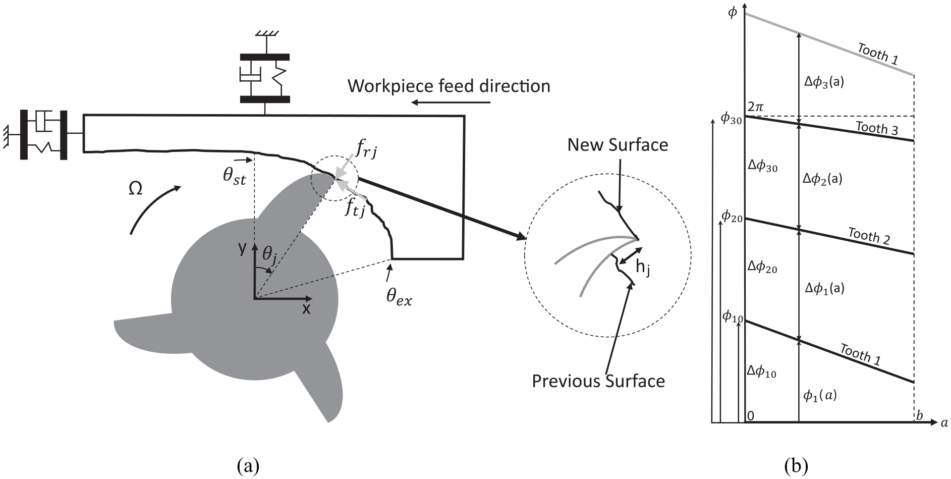
(a) Schematic of the process and (b) Geometrical parameters of the variable helix tool.
It is worth mentioning that


where N is the number of teeth, and
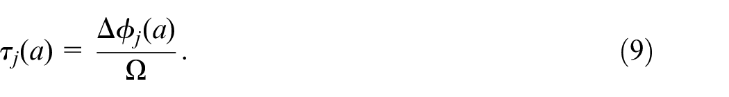
Once the tool starts to rotate at a spindle velocity

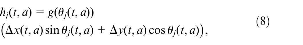
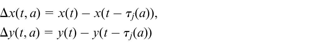
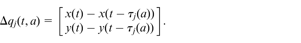
For the differential element of size da along the axial axis of the tool (Figure 2(a)), the flute j removes a chip thickness


in which
Next, the chip thickness can be calculated as,
where,
and,
Meanwhile,


Summing the cutting forces contributed by all teeth and integrating the infinitesimal element da from
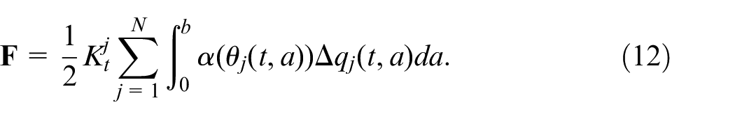
Here,
and
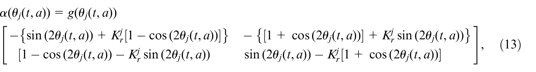
These forces are related to the system vibrations by the frequency-response denoted as
in which
As remarked in previous work, 28 equation (13) includes an exponential term that was neglected in earlier derivations of the Fourier series expansion. 40 This explains why these original derivations did not capture the influence of a constant but uniform helix angle on the tool stability.
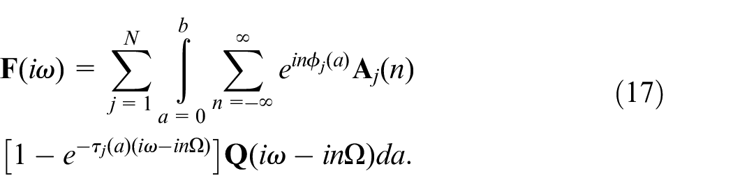
Applying the Fourier transform to the force in the equation (12), it can be rewritten in the frequency domain as,
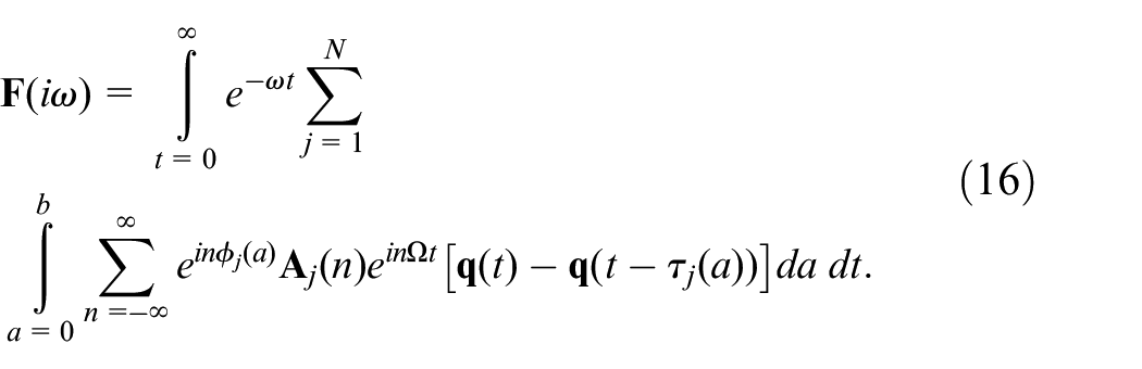
Here, i denotes
Therefore, the closed loop relationship between the vibration
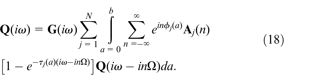
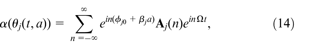
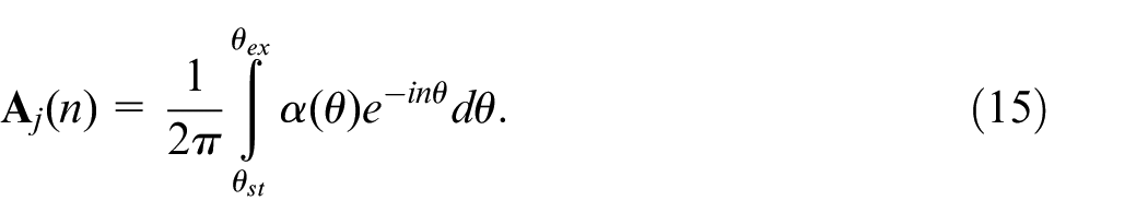
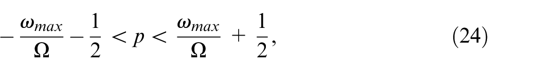
A more general expression for the frequency response at any harmonic p of the frequency response function can be obtained by rewriting
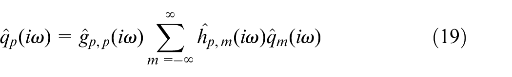
where,


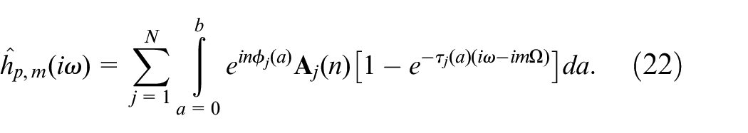
For compactness, (22) can be written in the following way:

However, it should be noted that this represents a doubly-infinite matrix equation, since
However, by taking advantage of the periodicity of
where
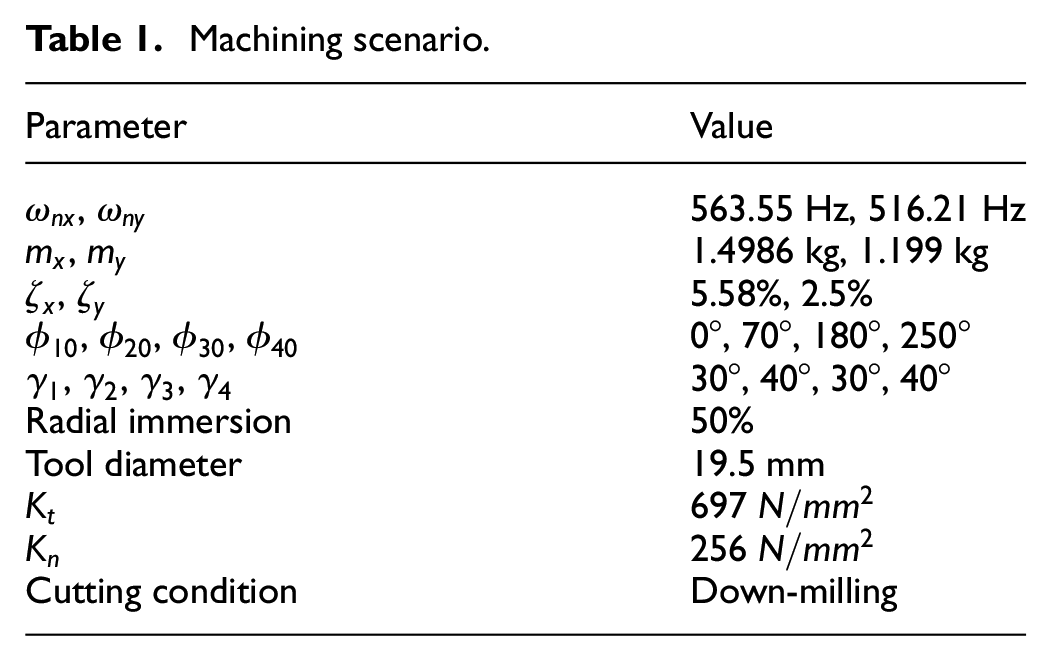
This theoretical approach was coded as a stability analysis algorithm using Matlab, and a preliminary validation achieved by comparing the predictions to those presented by Wang et al. 25 The machining scenario is outlined in Table 1, and the results are shown in Figure 3. It can be seen that the method agrees with previous work. However, as described earlier, the main focus of the present study is to explore the performance of variable helix tools in scenarios that cause islands of instability. To achieve this, a bespoke experimental configuration is required and this setup is now described.
Machining scenario.
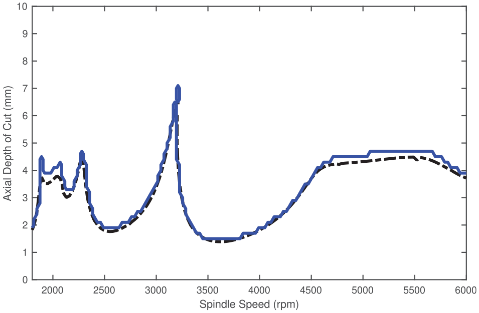
Comparison between the multi-frequency (solid blue line) and semi-discretization (dashed black line) approaches (
Preliminary workpiece design
Figure 4 shows the experimental configuration implemented in this project. The authors previously employed this setup in, 39 and it comprises an instrumented single-degree-of-freedom flexible workpiece mounted on a CNC machine (XYZ 1060 HS VMC). The main reason for implementing a single-degree-of-freedom (SDOF) flexible workpiece is to reduce the complexity of the process, minimising the risk of un-modelled influences such as mode-coupling vibrations, or nonlinearities in the structure or process. A SDOF scenario also makes it easier to obtain stability lobe predictions that exhibit islands of instability, without resorting to exhaustive optimisation algorithms such as those described by Yusoff et al. 43 Previous machining dynamics studies36,37,44 have frequently implemented this approach. However in the case of variable helix machining there is one drawback: the potential increases in stability that can be achieved from the tool can make it more difficult to enable SDOF behaviour at the necessary depths of cut. To overcome this, the flexure designed in the present study supports a workpiece made of copolymer acetal. This has a lower cutting force coefficient that enables linear SDOF behaviour from the system event at larger depths of cut. Furthermore, whilst material removal will inevitably change the natural frequency of the workpiece, the relatively low density of the acetal workpiece compared to the steel flexure, and the large volume of workpiece material compared to the volume removed, ensures that this issue becomes negligible for the present study.
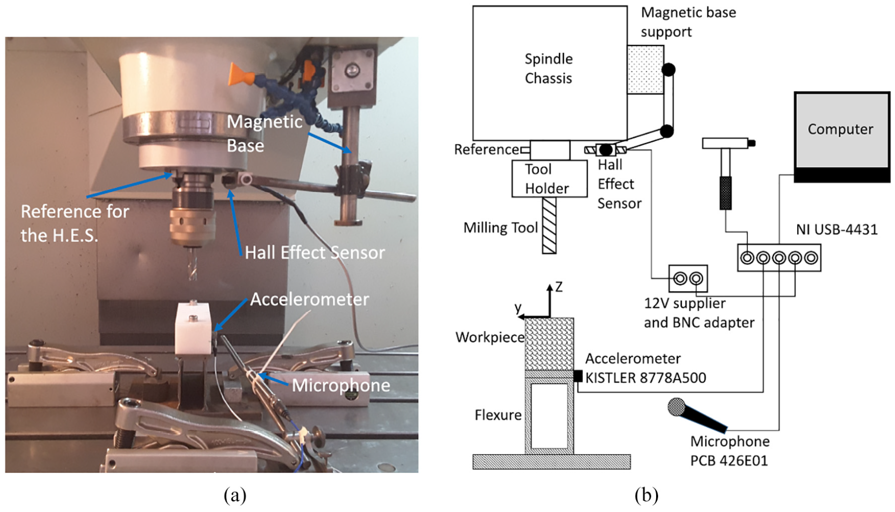
Experimental configuration (a) and schematic of the instrumentation (b).
Acetal is a semi-crystalline thermoplastic that provides high machinability, with low environmental sensitivity to factors such as humidity. Harper and Chanda45,46 considered this material as an engineering plastic with working temperatures of up to 100°C. More advanced engineering plastics like PEEK and PPS have higher working temperatures of about 150°C, but lower machinability. Also, they can cost 15 times the price of acetal.47,48 Acetal can be further divided into two categories: copolymer and homopolymer. Even though these materials behave similarly, homopolymer acetal has a higher centreline porosity compared with the copolymer side. To avoid any difficulty due to this, copolymer acetal was selected as the workpiece material.
Cutting forces
A preliminary stability analysis suggested that variable-helix tools with helix angles of 25, 15, 10° would give rise to unusual stability behaviour. Therefore, this subsection describes experimental observations of the cutting force coefficients for these tool geometries.
The main assumption of the mechanistic modelling (7) is that the cutting forces are proportional to the chip thickness. Although this is widely adopted in both research and industrial practice, there have been a number of studies proposing the use of non-linear models.49–52 The present study focusses on the assumption of linear cutting force coefficients, but also explores the possibility that the variations in helix angle can also influence the cutting force coefficients.
To achieve this, three single-fluted tools were manufactured, with helix angles of 25, 15, and 10° respectively. This allowed the determination of the cutting force coefficients independently, for a single flute with the given helix angle. The same methodology was then applied to a conventional tool of 25° of helix angle. With this approach, the aim is to detect any significant variation in the coefficients due to the helix angle. All the tools implemented in the experiment are part of the same material batch, guaranteeing homogeneity in the results. Custom tools were manufactured by Technicut Ltd.
Therefore, per every tool, a group of full-slotting trials at 5 mm of axial depth of cut was performed at feed-per-tooth values of 0.05, 0.1, 0.15 and 0.2 mm/tooth. The entire procedure was executed at spindle speeds of 1300, 2800, and 4300 rpm to further study any variation due to cutting speed. Table 2 summarises the results obtained from these tests.
Cutting force coefficients for a conventional milling tool of 25° of helix angle, and one-flute tools with helix angles of 25°, 15°, and 10°.
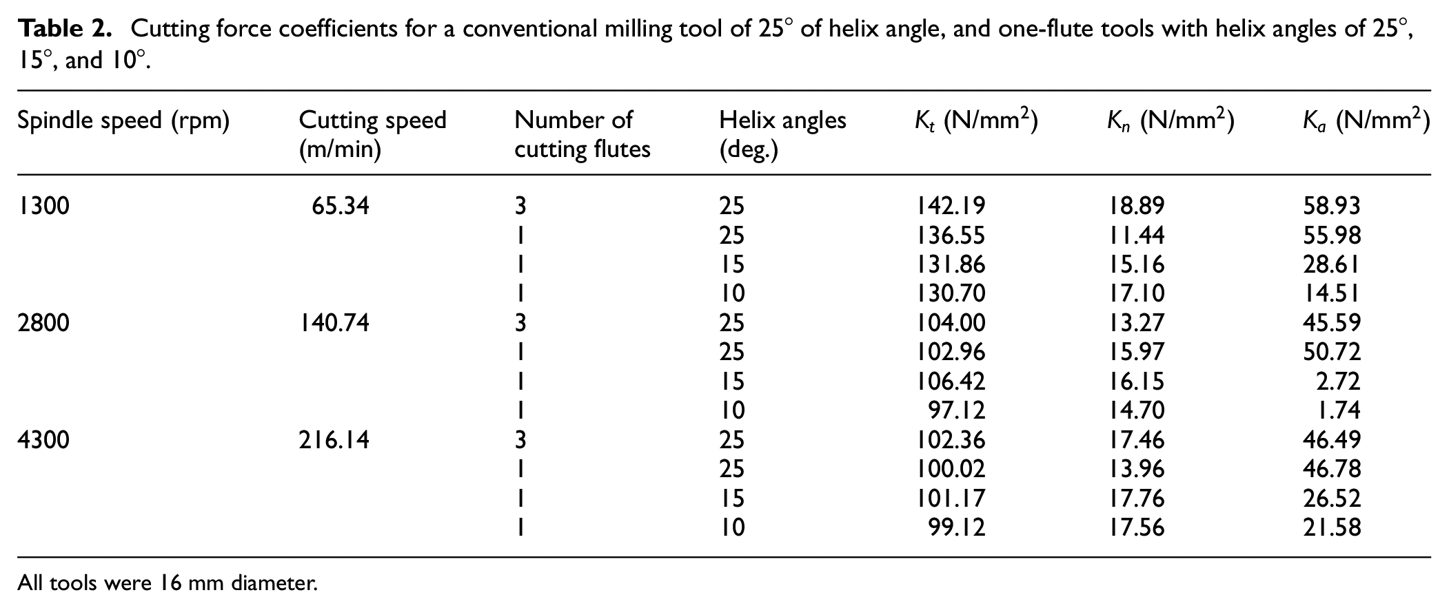
All tools were 16 mm diameter.
Regarding Table 2, for the spindle speed of 1300 rpm, the cutting force coefficients decrease in magnitude while decreasing the helix angle. However, the change is relatively small, and it is also worth highlighting that the cutting force coefficient in the normal direction (
Figure 5(a) shows the relation between the feed per tooth and the average forces for the conventional tool at 1300 rpm. The average cutting forces are proportional to the feed per tooth. Therefore, the assumption of a linear-force model with this plastic is reasonable.53–55 The same behaviour was found from the results with the one-flute tools.
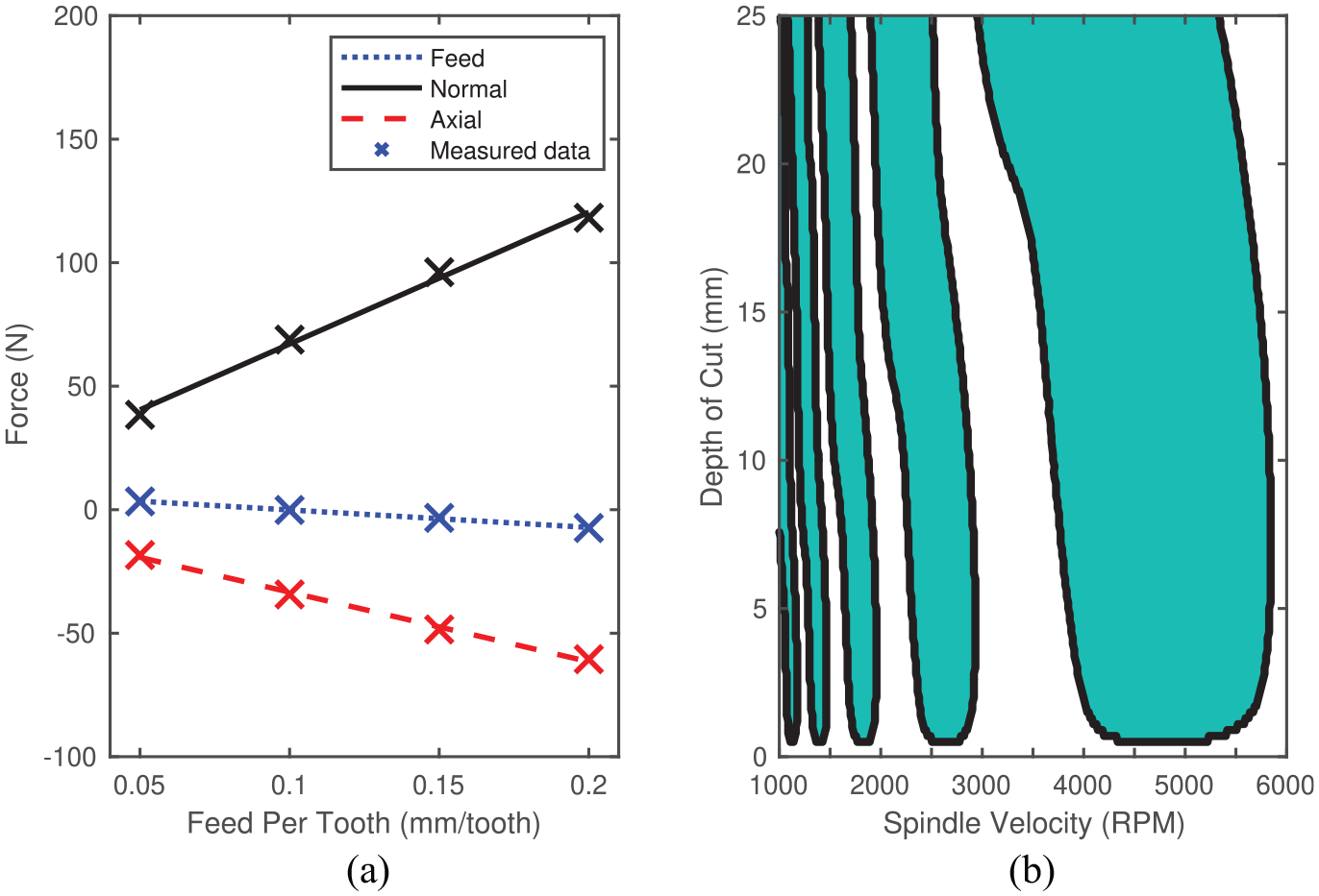
(a) Experimental results showing the relationship between the feed-per-tooth, and the average forces for a conventional milling tool with 25° of helix angle at 1300 rev/min. (b) Predicted stability lobes for a
Finally, to show how the coefficient variations affect the process stability, simulations were performed using the one-flute-tool coefficients. Later, the same simulation was executed using the conventional tool coefficient. As shown in Figure 5(b), the effect of the coefficient variations was negligible. This implies that the conventional-tool coefficients can be reliably used to estimate the stability boundaries.
To summarise, the chosen workpiece material exhibits machining behaviour that is consistent with the mechanistic cutting force model. Furthermore, it has been found that the helix angle only has a small influence on the mechanistic cutting force coefficients, and that this difference has a negligible impact on a typical stability lobe diagram. This paves the way for a validation of the model predictions, using a single degree of freedom flexible workpiece.
Structural dynamics and damping
Figure 6(a) shows the frequency response function of the flexure device with the attached workpiece, determined by performing an impact hammer test. The estimated modal parameters are a natural frequency of 296.82 Hz, a damping ratio of 0.153%, and a modal stiffness of 3.85 kN/mm. This device is 86 times more flexible than the system comprising the cutting tool, tool holder, and the spindle at the tool tip. Therefore, the assumption of a rigid machine tool is valid, meaning that the only source of instability in the processes comes from the workpiece vibrations.
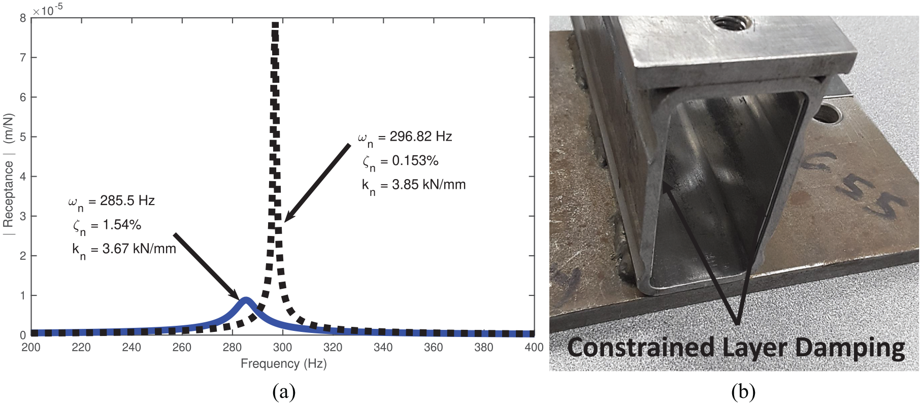
(a) Frequency response function of the flexure without the constrained layer damping (black dashed line) and with it (blue line). The natural frequency and stiffness of the system were slightly reduced while the damping was drastically increased by a factor of 10. (b) Placement of the CLD on the experimental flexure device.
One of the main aims of this work is to show the impact of structural damping on variable-helix instability islands. Therefore, constrained layered damping (CLD) was applied to the flexure as shown in Figure 6(b). The CLD comprises a layer of viscoelastic material attached by an adhesive to the most significant curvature regions of a host structure. 56 Then, when the structure deforms, it induces a shear deformation in the viscoelastic material that dissipates energy. To further increase the shear effect, a metallic laminate is attached to the other side of this layer to constrain its deformation.
Figure 6(a) shows the resulting FRF (blue line). The estimated modal parameters are a natural frequency of 285.5 Hz, a modal stiffness of 3.65 kN/mm, and a damping ratio of 1.54%. This damping level is over ten times the value in the initial structure.
To summarise, the flexible workpiece exhibits single-degree-of-freedom vibration response, to the extent that other structural modes within a machine-tool system can be ignored. Meanwhile, the addition of constrained layer damping has enabled an alternative response of the workpiece that is heavily damped. This configuration will now be used as the basis for parametric studies into the influence of damping and numerical convergence issues, when modelling the chatter stability of variable helix tools.
Analysis of damping
In this section, the stability model is applied to the experimental single-degree-of-freedom milling scenario in order to demonstrate the role of the damping of the machine tool structure.
Figure 7 shows the stability diagram obtained using the dynamic and force parameters determined in the previous section. To construct this diagram, the multi-frequency approach (MFA) was configured to predict stability in up-milling and half immersion. The feed direction (x in Figure 4) was normal to the flexural mode of vibration (y). The maximum frequency used in (26) was
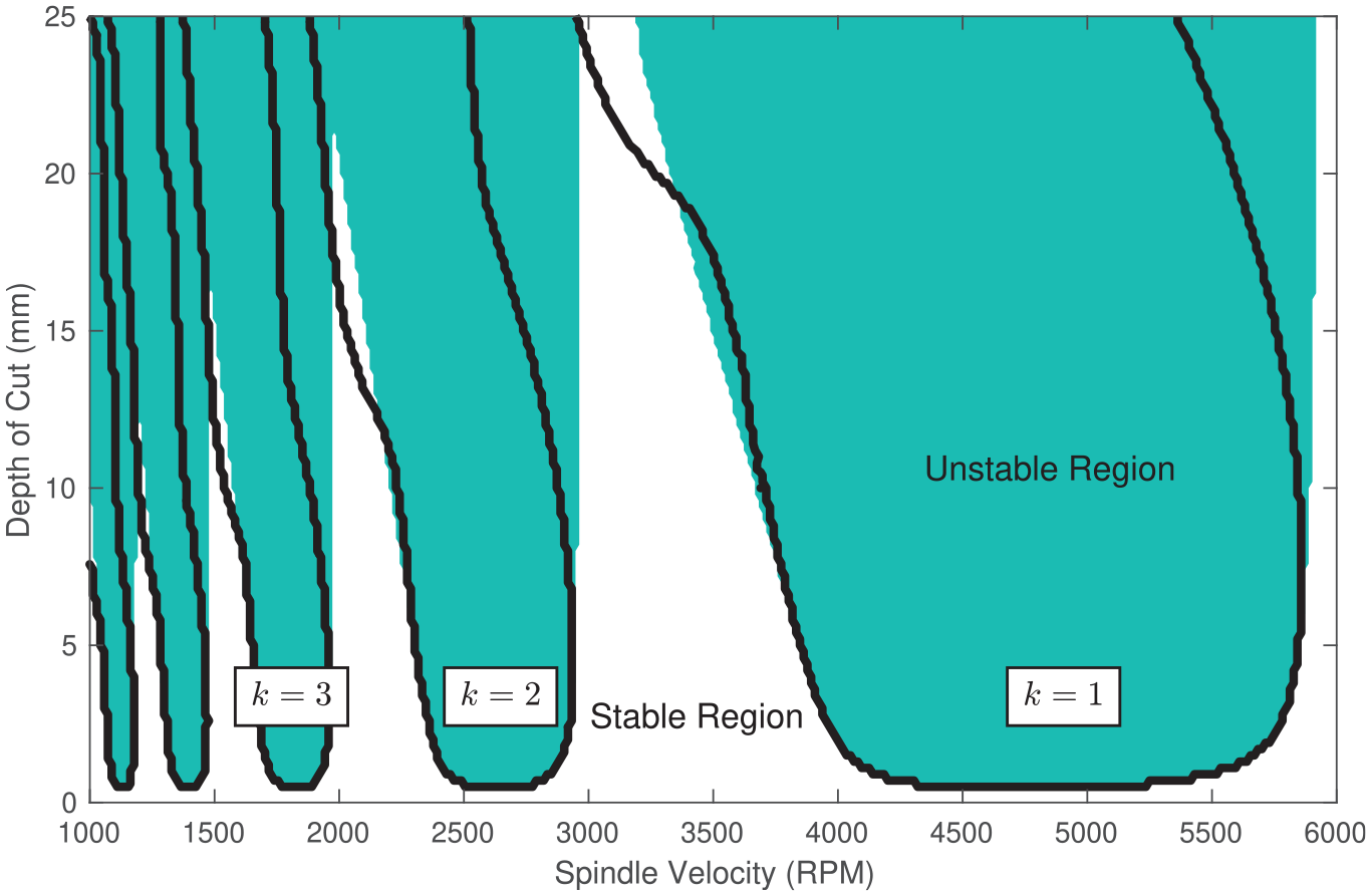
Black line: the stability lobe diagram for the
With reference to Figure 7, the filled area represents the stability predictions using a conventional tool, while the black line shows the variable helix predictions. Both of these predictions are based upon the original flexure design, with no constrained layer damping, and a modal damping ratio of 0.153%. The value of k represents the number of waves per revolution imprinted by the tool on the workpiece surface.
In the case of the regular helix tool, the stability is monotonic with respect to the depth of cut. This is commonplace for the secondary Hopf bifurcation case of regular helix tools. It is also notable that the stability boundaries do not exhibit regions associated with period doubling (or flip) bifurcations, due to the machining parameters that have been chosen (e.g. large radial immersion). The only difference with the variable helix result is that the stability is no longer monotonic with respect to the dept of cut: the lobes are skewed and at one specific spindle speed it is possible for the chatter to re-stabilise as the dept of cut increases. However, no unstable islands can be observed.
The role of damping is now illustrated by repeating the stability analysis for the variable helix tool, but with the damping ratio increased by a factor of up to ten. This result is shown in Figure 8, where the damping ratio scaling factor is denoted
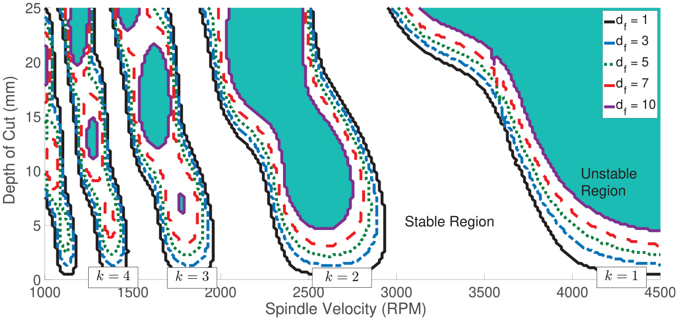
Effect of the damping on the stability lobe diagram for the VHM tool with helix angles of
As expected, the absolute minimum stability limit increases while increasing
This result clearly demonstrates that variable helix tools are expected to exhibit islands of instability. These islands are unlike those found for regular helix tools, which are typically associated with period doubling or flip bifurcations. However, the islands only emerge at relatively high levels of structural damping - greater than 1% of critical for the scenario under investigation. This suggests that normal machine tools and structures might need supplemental damping treatments or systems before islands of stability could be harnessed in practice.
Analysis of convergence
This section explores the convergence of the stability predictions, with particular emphasis on the islands of instability that emerge when there are high levels of structural damping.
As mentioned previously and described in, 28 the stability analysis used in the present study features guaranteed convergence. This is based on the assumption that the system’s frequency response function can be truncated (and assumed zero) above a specific frequency. To illustrate this, the convergence of the present approach is now compared to the semi-discretisation method.13,18
With reference to Figure 8, a convergence study is performed around the instability island that appears for the variable helix tool, between 12 and 22 mm, for the
In order to illustrate the convergence of the MFA method, the number of harmonics p was chosen manually rather than using (24). For each value of p, the upper and lower chatter stability boundaries of the island were predicted.
A similar procedure was followed for the semi-discretisation method, where the number of samples per revolution M must be chosen to ensure convergence. In practice this choice depends upon the spindle speed and the natural frequencies of the structure. Consequently in the present study the convergence is plotted against a normalised parameter,
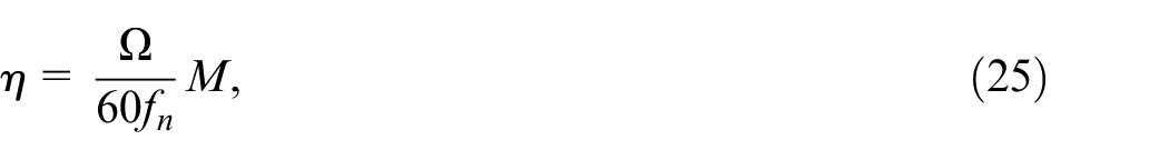
where
The results of the convergence study are shown in Figure 9. Here, the y-axis denotes the axial depth of the cut for the upper and lower stability boundaries of the unstable island. The upper x-axis shows the number of harmonics p for the MFA approach, and the lower x-axis shows the number of iterations
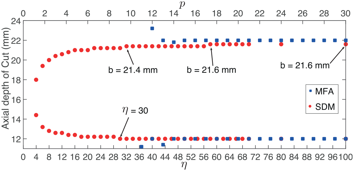
Convergence Analysis for the MFA and SDM. The MFA data shows the convergence of the depths of cut stability boundaries for different numbers of harmonics p (top axis scale), whereas the SDM method shows convergence for different values of
From Figure 9, the blue squares and upper x-axis show that the minimum p value to at least detect one of the island boundaries is
The MFA approach rapidly converges once p is increased above 12, to predict an unstable region between 12 and 22 mm. The solution can be considered to have converged fully once
The results for the SDM are shown as red dots in Figure 9, and corresponding values of
To summarise, the convergence of the MFA method appears to be superior to that of the SDM method, for the specific case of variable helix tools. Furthermore, the MFA method presented here can offer guaranteed convergence based upon physically motivated assumptions. Most importantly, for either algorithm the convergence plays a critical role in the prediction of unstable islands for variable helix tools.
Experimental validation
This section seeks to validate the presence of unstable islands via a series of machining trials.
As with the convergence study, the unstable island for the
To detect chatter in the milling trials, the flexure was instrumented with a uni-axial accelerometer (KISTLER model 8776A50) attached with wax, and a microphone (PCB-377B20 with pre-amplifier PCB-426E01) as shown in the schematic of Figure 4(b). It should be noted that accelerometer mass-loading effects were negligible due to the design of the flexure (workpiece mass was over 400 g) and the mass of the accelerometer (4 g). To study the types of bifurcation occurring in the unstable tests, once-per-revolution values are obtained from the acceleration time series by using the data collected from a Hall-effect sensor. This sensor is configured to provide a voltage pulse periodically with the rotation of the spindle. Finally, all the sensors are connected to a data acquisition device (NI DAQ USB-4431), that is linked to a laptop by USB.
Thirteen spindle speeds from 1440 rpm to 1680 rpm were defined at increments of 20 rpm. At every speed, a group of seven trials were executed at non-equal spaced axial depth of cuts. Additional tests were then performed around specific areas to better estimate the boundaries near the island. The trials were done using a feed per tooth of 0.05 mm/tooth, half immersion, and up-milling condition.
For each test, the acceleration once-per-revolution samples were used to construct a delayed Poincaré section. This was used to qualitatively classify the process stability: if the delayed Poincaré section appears as a fixed point, then this indicates a stable process. Note that for a variable-helix tool, the fundamental period is the tool rotational period rather than the tooth-passing one. In addition, the Fast Fourier Transforms (FFT’s) of the audio and acceleration signals were computed. In the stable case the FFT’s should show the spindle-pass frequency or any of its harmonics as dominant in the process. In theory, these methods should all produce the same classification of stability. In practice, the classification based upon the FFT of the acceleration signal always agreed with that from the Poincaré section. However, the classification based upon the FFT of the sound signal did not always agree with that of the Poincaré section, and so these scenarios were classified as marginally stable.
The results are summarised in the stability lobe of Figure 10. Here, green dots represent stable tests while red squares are unstable ones. Marginally stable cases are shown as orange diamond markers. Overall, good agreement was found between the experiments and the estimated stability boundaries. Most importantly, the experiments show an instability island close to the predicted behaviour. To the authors’ knowledge this is the first time that such an islands has been observed experimentally.
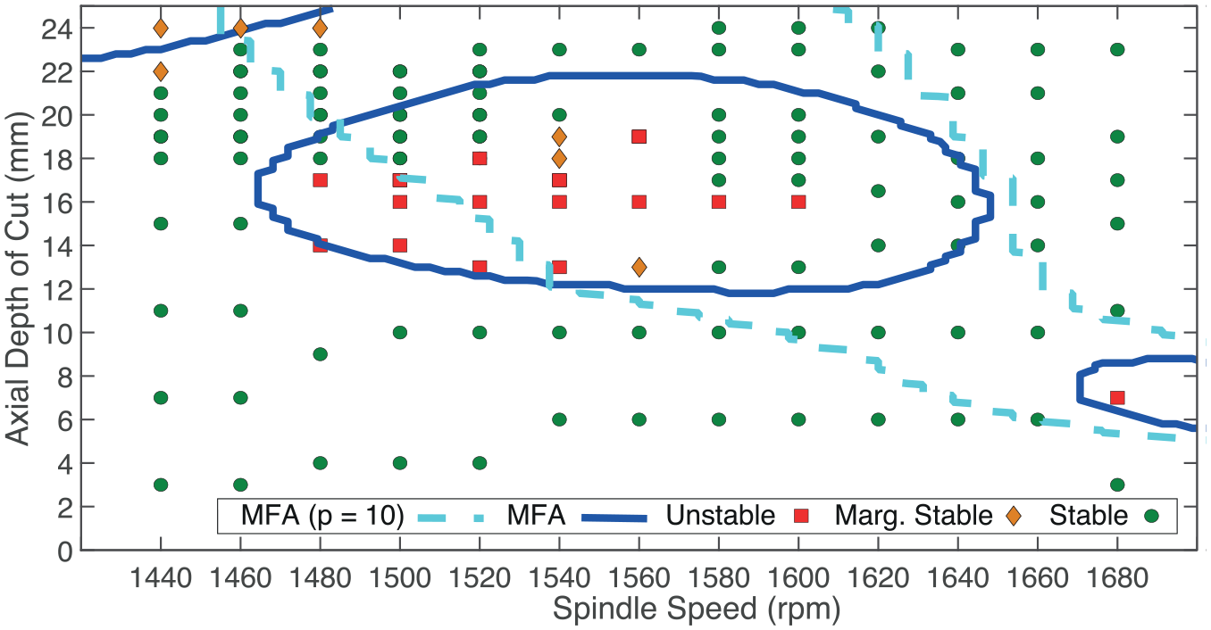
Stability lobe validation for the damped flexure and a
A detailed example of the results obtained at 1540 rpm is shown in Figure 11. Here, the left column shows the acceleration time series in blue lines, with once-per-revolution samples superimposed as red dots. The green square indicates the steady-state region, manually chosen to build the Poincaré section shown in the second column. The final column shows a surface profile. It is clear from Figure 11(a) that the process is stable. At 13 mm (Figure 11(b)) the Poincaré section reveals a small transition to a quasi-periodic motion, associated with a secondary Hopf bifurcation. 32 As the axial depth of cut is increased to 16mm, the magnitude of this quasi-periodic motion also increases. At 19 mm, even though the acceleration FFT and Poincaré section suggested that the process was stable, the sound signal FFT revealed the opposite, and so this was classified as marginally stable. At 20 mm, the process becomes fully stable, and the dominant frequency corresponds to a tool-passing-frequency harmonic.
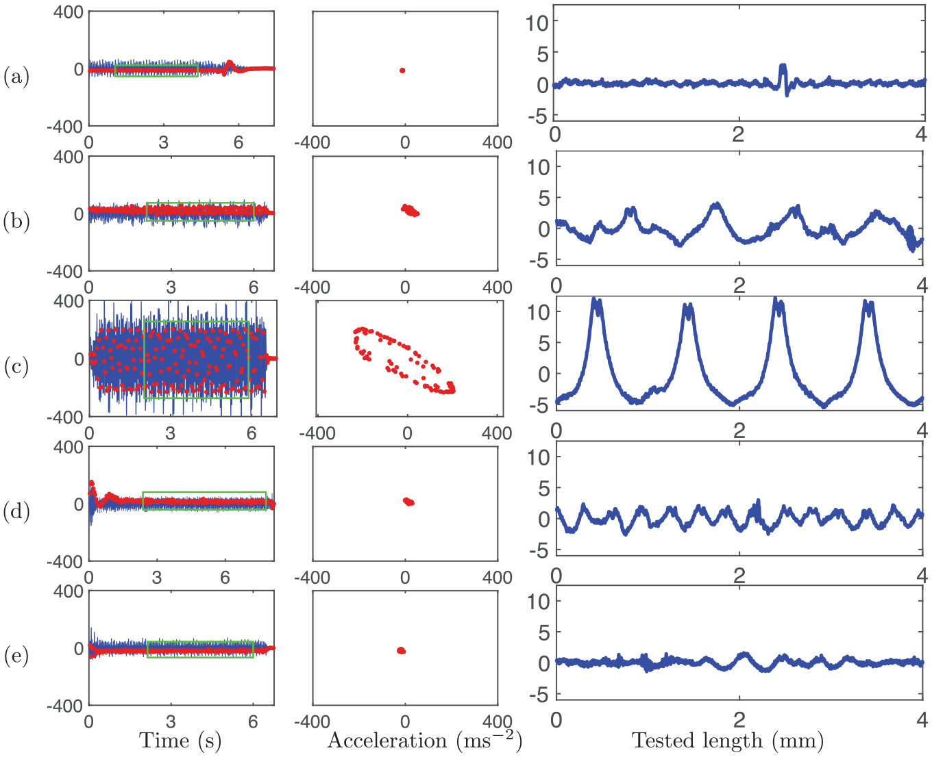
Stability analysis. The left column shows acceleration time series (in ms−2), and the middle column shows once per revolution delayed Poincaré samples of the acceleration signals, with the same
Returning to Figure 10, the importance of the convergence parameter p is further illustrated by the cyan line. Here, the stability prediction is shown for a non-converged solution, where
To further validate the modelling approach, a similar procedure was performed for a different tool geometry (
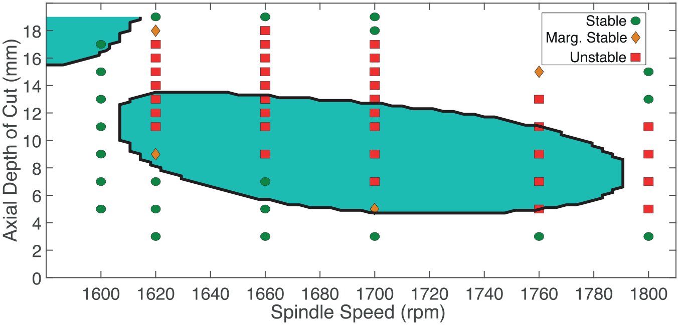
Stability lobe validation for the
For this tool, a ramped-axial-depth-of-cut test was performed using a ramped workpiece with a similar mass as the original one. Its height varied from 3 to 17 mm across the 170 mm length of the cut. The results are shown in Figure 13. Here, the acceleration data (blue lines) and the once-per-revolution samples (red dots) are plotted against the axial depth of cut (lower x axis) and time (upper x axis). The test starts as a stable process after a small transitory region. At about 4.5 mm depth of cut, instability occurs. A lower sweep-rate would be needed to properly determine whether this is associated with a period-doubling bifurcation or a Hopf bifurcation. The process becomes stable as the depth of cut increases beyond 14 mm. These results agree with the stability predictions presented in Figure 12.
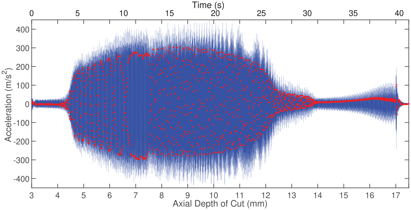
Acceleration and once-per-revolution values of the ramped workpiece test with the
Overall, the experimental and analytical results both indicate the presence of unstable islands. There is reasonable agreement between the model and experiment, but there are some discrepancies in the location of the unstable islands, for both of the tools that have been tested. These discrepancies are most probably due to changes in the stiffness and damping of the workpiece between each test configuration. For example, re-mounting of the workpiece material on the flexure, and re-clamping of the flexure onto the machine bed, will potentially change the boundary conditions and hence the stiffness. Meanwhile, the performance of the constrained layer damping treatment is well-known to be temperature dependant, and the bonding of the CLD to the flexure could have degraded during the experiments.
Conclusions
In this study, the dynamics of variable helix milling tools have been explored using a novel stability analysis approach with rigorous experimental validation. It can be concluded that:
Variable helix tools can exhibit large islands of instability on the stability lobe diagram. These have been experimentally validated for the first time.
The islands of instability have been shown to be highly dependent on the structural damping values within the system. Specifically, islands of stability were not observed at levels of damping less than 1% of critical, which suggests that normal machine tools and structures might need supplemental damping treatments / systems before this stability could be harnessed in practice.
The stability analysis methods for variable helix tools are susceptible to convergence issues, and this is particularly important when seeking to identify islands of instability.
Using a multi-frequency solution approach based upon a harmonic transfer function ensures a guaranteed convergence of the stability prediction, overcoming this convergence issue.
These findings indicate that variable helix tools could be of even greater practical benefit, whereby large depths of cut can be possible on realistic machining scenarios. Achieving this will require particular attention to the convergence and accuracy of stability predictions. The role of structural damping needs further investigation in order to inform tool geometrical designs, and the prediction accuracy may be improved by further analysis of repeatability and nonlinearity effects.
Footnotes
Declaration of conflicting interests
The author(s) declared no potential conflicts of interest with respect to the research, authorship, and/or publication of this article.
Funding
The author(s) received no financial support for the research, authorship, and/or publication of this article.