
Abstract
Facility layout design is becoming more challenging as manufacturing moves from traditionally emphasised mass production to mass customisation. The increasing demand for customised products and services is driving the need to increase flexibility and adaptability of both production processes and their material handling systems. A holistic approach for designing facility layouts with optimised flows considering production and logistics systems constraints seems to be missing in the literature. Several tools, including traditional methods, analytic hierarchy process, multiple-attribute decision making, simulation, and optimisation methods, can support such a process. Among these, simulation-based optimisation is the most promising. This paper aims to develop a facility layout design methodology supported by simulation-based optimisation while considering both production and logistics constraints. A literature review of facility layout design with simulation and optimisation and the theoretical and empirical challenges are presented. The integration of simulation-based optimisation in the proposed methodology serves to overcome the identified challenges, providing managers and stakeholders with a decision support system that handles the complex task of facility layout design.
Introduction
Acquiring flexibility and adaptability in production systems is one of the major challenges in competing with the rapidly changing manufacturing industry worldwide.1,2 This challenge is especially demanding in old production facilities with suboptimal shop-floor layouts and production flows, 3 characterised by a continuous adaptation process or patching of the production facilities for decades, quite often without an overall and long-term plan and a lack of a methodology for effective long-term shop-floor layout. The current tendency of mass customisation, shortened product life-cycle, and globalisation of manufacturing sites and suppliers highlight the need for flexible and effective shop-floor layouts. An effective shop-floor layout should be able to adapt to the current production demands, and those generated from future products, variants, and volume changes.4,5 To address production demands, this research relied on a case study method to analyse the implications of challenges identified for manufacturing and ways to overcome them. Hence, an initial understanding of simulation-based optimisation (SBO) and facility layout design (FLD) was acquired, and going through two industrial case studies, empirical challenges of SBO in FLD were identified. The main research question in this paper is ‘how an SBO approach can be integrated into a methodology to facilitate the layout design process considering production and logistics constraints’.
Firstly, According to Oates, 6 a methodology can be considered a procedure or set of procedures, rules, or principles to address problems in organisational situations. An example of the main stages of a methodology can be awareness, suggestion, development, evaluation, and conclusion. Secondly, FLD can be defined as the physical allocation of space on a shop floor involving the relative positioning of resources and their functions in the economic activity of a plant. 7 At a strategic level, FLD can significantly improve productivity by reducing material handling costs and lead time. 8 Finally, SBO has commonly been used to find solutions to complex design problems when the size and number of possible decision variables used as parameters are considerably high. 9 Using SBO for FLD is essential because it can provide a deeper understanding of the dynamic nature of floor space utilisation in production systems. Hence, this paper aims to identify the challenges of SBO and FLD and propose a methodology to mitigate these challenges. The content of this paper is divided as follows: Section 2 presents the current literature on FLD and SBO and theoretical challenges; Section 3 summarises the empirical challenges of SBO and FLD through two industrial case studies; Section 4 presents the proposed methodology; Section 5 presents the validation of the methodology; and Section 6 presents the conclusions of the study.
Facility layout design and simulation-based optimisation
For production plants to be competitive, facilities must be analysed and redesigned periodically and flexible, modular, and easily reconfigurable layout designs should be facilitated. 10 To solve the facility layout problem, FLD can be used, which is defined as the task of designing the allocation plans of departments, cells, machines, or equipment on a manufacturing shop floor.10,11 The objective is to ensure effective use of the floor space, a smooth and steady flow of production material, equipment, and manpower, and to minimise the use of the material handling systems. 11 To better understand the state-of-the-art of how simulation and optimisation are used to approach FLD, we conduct literature review.
The FLD literature review in this research was performed using Scopus and Web of Science with the search string ((facilit* OR shop* OR workshop* OR layout*) W/3 design*) AND (simulat* W/2 optimi*) AND (method* OR approach*)), including articles from 1999 to 2019, resulting in 181 and 110 articles, respectively, the majority of which overlapped.
Previous studies categorise FLD problems as either static or dynamic.10,12,13 In static problems, the layout is generated for a specific time period, the flow between machines never changes, and the product demands and product mix are fixed. 10 Dynamic layout problems involve fluctuations in product demand and product mix, changes in production processes, introduction or discontinuation of products or machines, and other factors that can affect the material handling system. 10 This research is analysed from the perspective of multiple dynamic layouts for various time horizons. 10
One traditional method for solving the facility layout problem was the quadratic assignment problem (QAP). However, the complexity of today’s production systems and shop floors limits the utilisation of this technique. 14 Additionally, owing to some characteristics of real-world problems, such as the random nature of data or stochastic data, FLD problems cannot be easily modelled without the use of simulation. 15 Using simulation approaches makes it easier to address the system capacity constraints and resource requirements. 15
Currently, computational advances facilitate the use of SBO to increase the competitiveness of production systems. Some of the most used methods to deal with FLD problems are discrete-event simulation, meta-heuristics, hybrid meta-heuristics, and mathematical optimisation modelling approaches.4,5,9,11,16–21 Several authors have used simulations for the design of facility layouts. Azadeh et al. 8 presented an integrated approach with simulation and mathematical programming for the maintenance process of a gas transmission unit considering resilience engineering factors and several layout configurations. The authors concluded that using a multifunctional machine could significantly improve the key performance indicators of the maintenance workshop, especially by decreasing material handling distances and waiting times before the processes. They also concluded that an increase in the number of operators would not have a significant positive effect unless the layout is improved. The different steps in their integrated fuzzy simulation approach were used to construct the methodology presented in section 4.
Yang and Hung 22 proposed a fuzzy multiple-attribute decision-making method for layout design in a packaging company, TOPSIS. They considered three quantitative attributes: material handling distance, adjacency score, and shape ratio, and three qualitative attributes: flexibility, accessibility, and maintenance. The decision-making portion of the methodology (section 4) has addressed how the different parameters have been considered. A complete work on a mixed-integer nonlinear programming model for the layout design of a dynamic cellular manufacturing system is presented by Kia et al. 23 They consider cell formation, group layout, and group scheduling, including the material handling system, machine capacity to minimise the inter-cell material handling and machine utilisation, relocation, and purchase. An extension of the work is presented in a multi-floor environment, also considering a multi-period planning horizon. 24 In these two cases, demand variability and unequal area facilities were not considered. However, the integration in a dynamic environment of alternate process routings, operation sequences, processing times, production volumes, machine capacity, lot splitting, intra-cell layout, inter-cell layout, and flexible reconfiguration has served as an inspiration for the development of this methodology.
Shah et al. 10 presented dynamic facility planning under production and material handling capacity constraints, where they developed a methodology for designing layouts under dynamic conditions of product demands, changing from period-to-period and considering production and material handling capacity constraints. Some aspects of the methodology presented by Shah et al. 10 have also been considered for constructing the methodology presented in section 4, especially the aspects related to production and logistics constraints. However, when the size and complexity of the system to be analysed are considerable, this methodology could be complemented with an SBO tool for the election of the final layout candidates, with their corresponding production and logistics systems.
In summary, there is a wide range of methods available for solving the facility layout problem specifically. Nevertheless, the integration of these methods with simulation has not been extended. A methodology to integrate simulation and optimisation to solve the facility layout problem appears to be missing. Additionally, the consideration of production constraints (machining and assembly lines) and internal logistics constraints (material handling systems), combined with simulation and optimisation, is not extensive and is far from being implemented.
Moreover, the literature identifies several challenges in working with SBO and FLD. First, there are challenges inherent to the nature of simulation or optimisation. Second, there are challenges affecting the resources that support SBO in manufacturing, which may include people, processes, or technologies. A summary of the main challenges, which are extensively discussed in our recent conference paper, 25 is presented in Table 1.
Challenges affecting SBO and FLD reported in the literature.
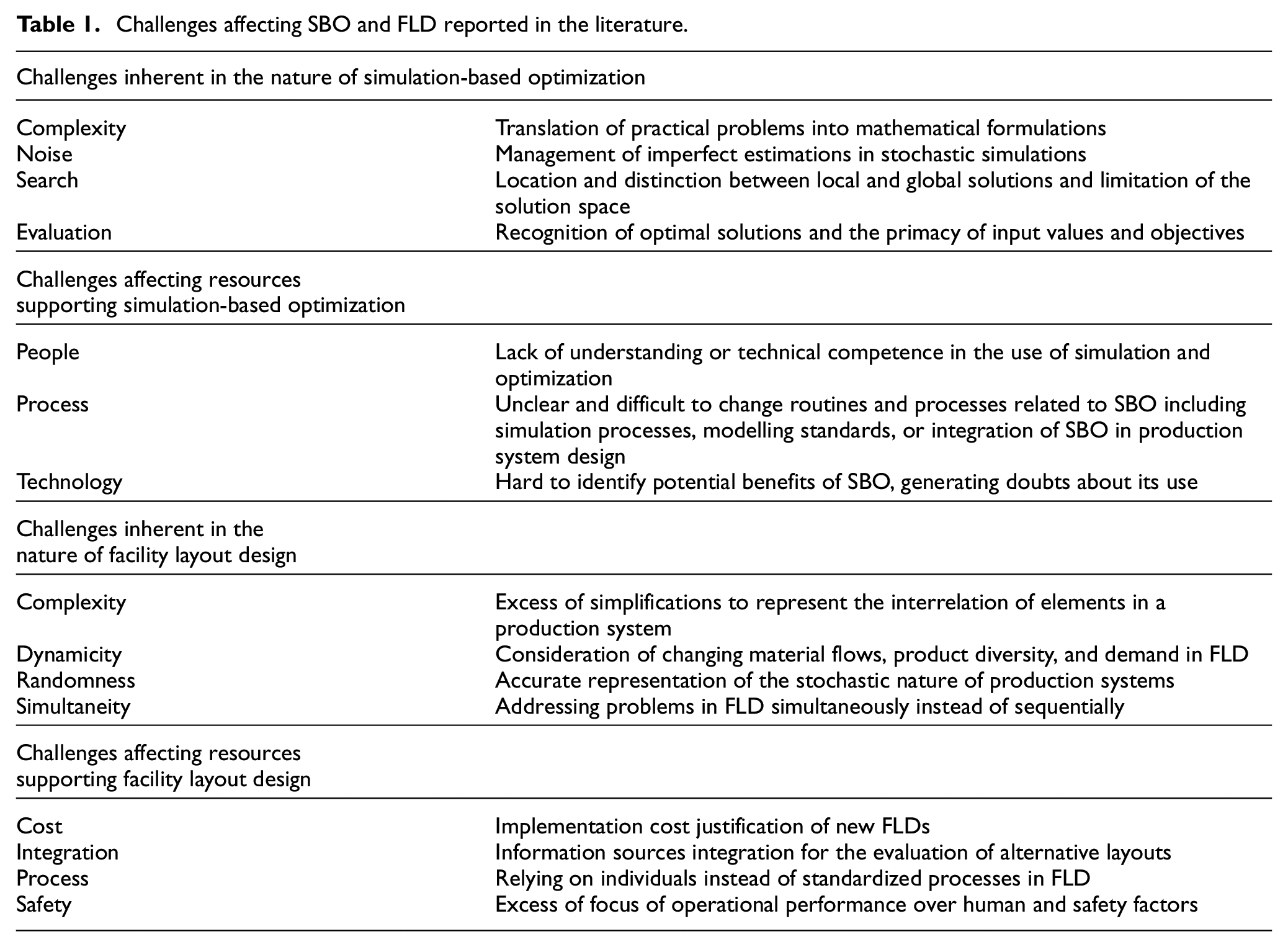
Owing to these challenges, the design of an effective layout can be a tedious task. A list of empirical challenges of using SBO in FLD is presented in section 3, and the proposed methodology to overcome them in section 4.
Empirical challenges of facility layout design with simulation-based optimisation
Theoretical challenges found in the literature did not always match the requirements and empirical challenges identified in the industry. To identify these empirical challenges, two cases (A and B) were considered based on the following criteria: the manufacturing company was planning an FLD project; it was anticipated that SBO would be used in the FLD project, and the staff anticipated challenges that would jeopardise the success of SBO models. Case A involved an FLD project, including SBO at a medium-sized manufacturing company specialising in the production of electrical cabinets. The aim was to analyse the operational performance with simulation and optimisation, considering the factory floor space and production flows to meet increasing demand and product variety. Case B involved an FLD project, including SBO at a large manufacturing company specialising in the production of water pumps. The aim was to redistribute the factory floor space to integrate new production systems. Case B involved simulation and optimisation and included the relocation and merging of some of the assembly lines and the logistics systems associated with them. More information regarding the industrial case studies can be found in Ruiz Zúñiga et al. 25 Table 2 identifies the challenges of using SBO in FLD in case studies A and B.
Challenges of using SBO in FLD for cases A and B.
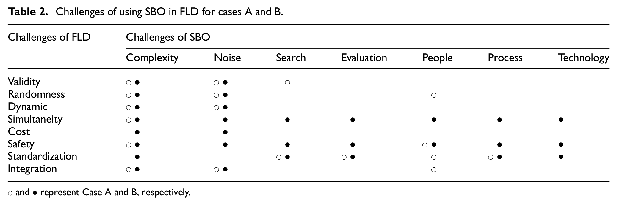
○ and • represent Case A and B, respectively.
Identifying the challenges affecting SBO and FLD included five steps. The first step involves condensing all collected data (e.g. interviews and company documents) in a spreadsheet and conducting an in-depth analysis, marking interesting passages referring to SBO and FLD challenges. The second step involved coding common words and phrases mentioned in the collected data (first-order codes). The codes expressed the opinions of the staff in their own words. For example, the following excerpt taken from a meeting with the plant manager of Case A was coded as an oversimplification of the design objectives: Fixing our layout was critical to the operation. Initially, we rushed towards a solution and, in doing so, simplified our problem. We gave precedence to the characteristics of our conveyor, and only at a later stage did we consider the interaction of operators, our welding station, and its quality check.
The third step is to compare first-order codes to prior literature about SBO and FLD. To do so, we relied on the definitions of the challenges presented in Table 1. The fourth step considered refining and thematically classifying coded data into SBO and FLD challenges as reported in the literature. For example, the code mentioned above was classified into the category of complexity (e.g. excess simplification to represent the interrelation of elements in a production system) in challenges inherent to facility layout design. In the fifth step, the authors discussed the results of thematic coding and its classification, and further refined and related the collected data to the aim of the study.
The following conclusions can be drawn from Table 2: First, it shows that the challenges of using SBO in FLD identified in the literature are not the most important factors in industrial environments. Instead, the most important challenges are complexity and data noise. These reflect a lack of planning, task division, and structured data collection. Second, it shows that the challenges are not technological in nature, but stem from production and logistics increasing the complexity of the production plants.
Facility layout design methodology with simulation-based optimisation
This section proposes an FLD with SBO methodology to mitigate the identified challenges of using SBO in FLD. The methodology is based on three aspects: the empirical data from Cases A and B, including FLD and SBO, interviews, and joint activities with layout engineers (e.g. developing SBO models) during FLD; the challenges identified in the literature (section 2) and; the research strategy of Action Research and Design and Creation 6 to develop the methodology. Figure 1 presents the proposed FLD with the SBO methodology.
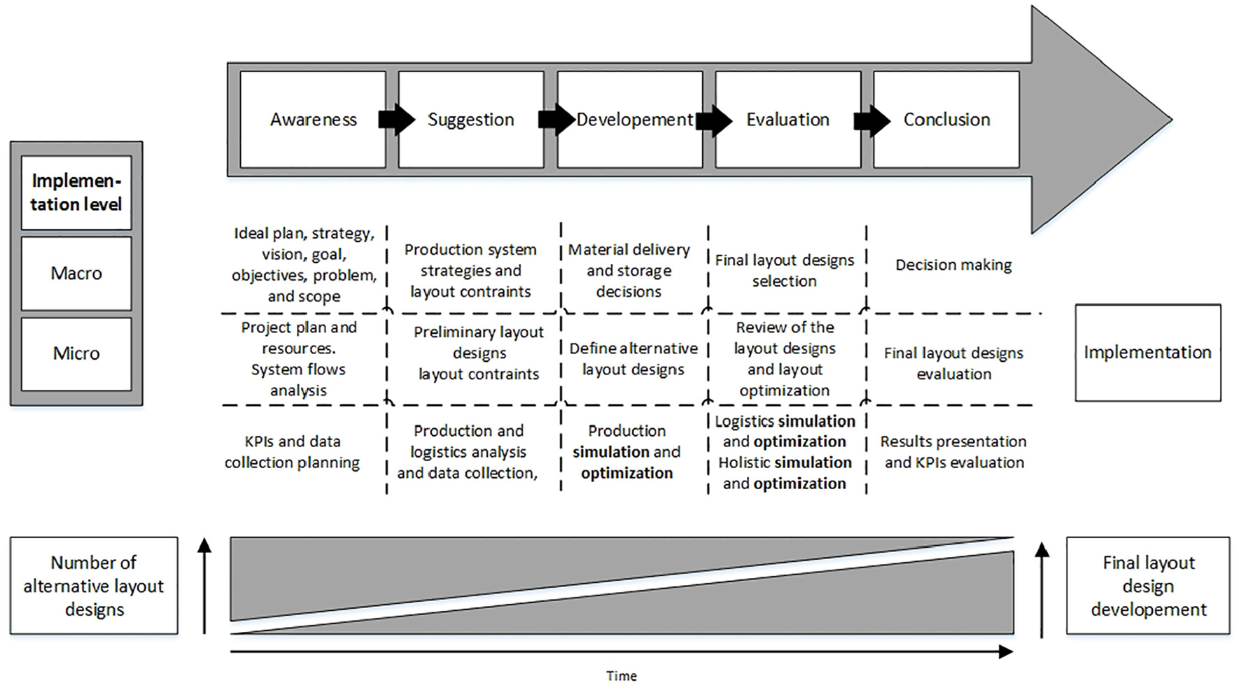
Methodology for the design of facility layouts with SBO.
The methodology comprises five stages. These stages follow a progression leading to the implementation of the FLD with SBO. The first stage, awareness, refers to recognising and articulating the problem of interest. The second stage, suggestion, involves the development of design alternatives. The third stage includes the development and selection, refinement, and implementation of design alternatives. The fourth stage includes evaluation, and examines the results of FLD alternatives with SBO, and their deviations from expectations. The fifth stage, conclusion, refers to consolidating the results of FLD with SBO.
Additionally, the FLD with SBO methodology includes macro-and micro-implementation levels. The micro implementation level includes operational aspects emphasising SBO support. Simulation experts or engineers, project leaders, and flow analysts are responsible for the micro implementation. The macro implementation level considers strategic and tactical support at the organisation or factory level. Strategic planners and the corporate management team are responsible for the macro implementation. 26 The implementation order of micro and macro levels includes a top-down approach for awareness, suggestion, and development, and a bottom-up approach for the evaluation and conclusion stages. The different development stages are presented here.
Awareness: After going through various case studies and benchmarked companies and analysing the interviews conducted with their engineering team members related to FLD, a common lack of planning and time to execute the projects was identified. Picturing an ideal plan of the company or site and its strategy and vision are key aspects to ensure a proper definition of the project. Clear definitions of the goal, objectives, problem description, scope, departments, and divisions involved will facilitate the managers and project team to visualise the expected results of the project and to create a detailed and realistic project plan. Especially when the size of the project is considerable, enough time to plan, from the moment the problem is identified until the definition of a preliminary project plan, is a key aspect for the proper development of the layout design. At this stage, the management team together with the stakeholders of the project, the people responsible for the layout, the engineering/technician team involved, and simulation and lean experts, should be involved in the awareness stage. The scope has to define, for example, the inclusion of possible changes or improvements in production systems (such as machining and assembly processes) and logistics systems (such as internal and external logistics, material storage, and material handling systems), as well as the need for and availability of data related to this scope. The election of a person for the key role of project management with sufficient experience can be a key factor for the success of the project. 27 For example, Case B benefitted from a project manager coordinating the different engineering teams and involving a lean and a simulation expert to support the engineering teams from the beginning was crucial for the good development of the layout design project. Once this awareness stage has established the aim, objectives, boundaries, and staff involved in the project, the next stage is the suggestion stage.
Suggestion: At this stage, it is time to complement all the preliminary information obtained during the previous stage. The continuation of a more specific data collection process, the consideration of possible strategies and methods for improving production systems and the required logistics systems are key steps. This additional information can be analysed to develop a realistic project plan and obtain the preliminary layout designs. This should include different production system alternatives and their required logistics alternatives, considering the constraints regarding the layout. The determination of the different areas or departments in the layout, aisles, plant services, and identification of the workstations, products and variants, lead times, and storage requirements should be the crucial steps at this stage. Consequently, performing detailed value-stream mappings of the current and future states for the identification of the relevant processes and analysing whether the use of simulation is required, is strongly recommended. More specifically, one should state if the use of discrete-event simulation is required due to the nature and complexity of the systems in the scope of the FLD project in every case.
Furthermore, with the support of the current and future state value-stream mappings, the conceptual models of the production and logistics systems and their requirements and constraints will be clearly defined at this stage. Figure 2 shows the conceptual model of the production of electrical cabinets in Case A.
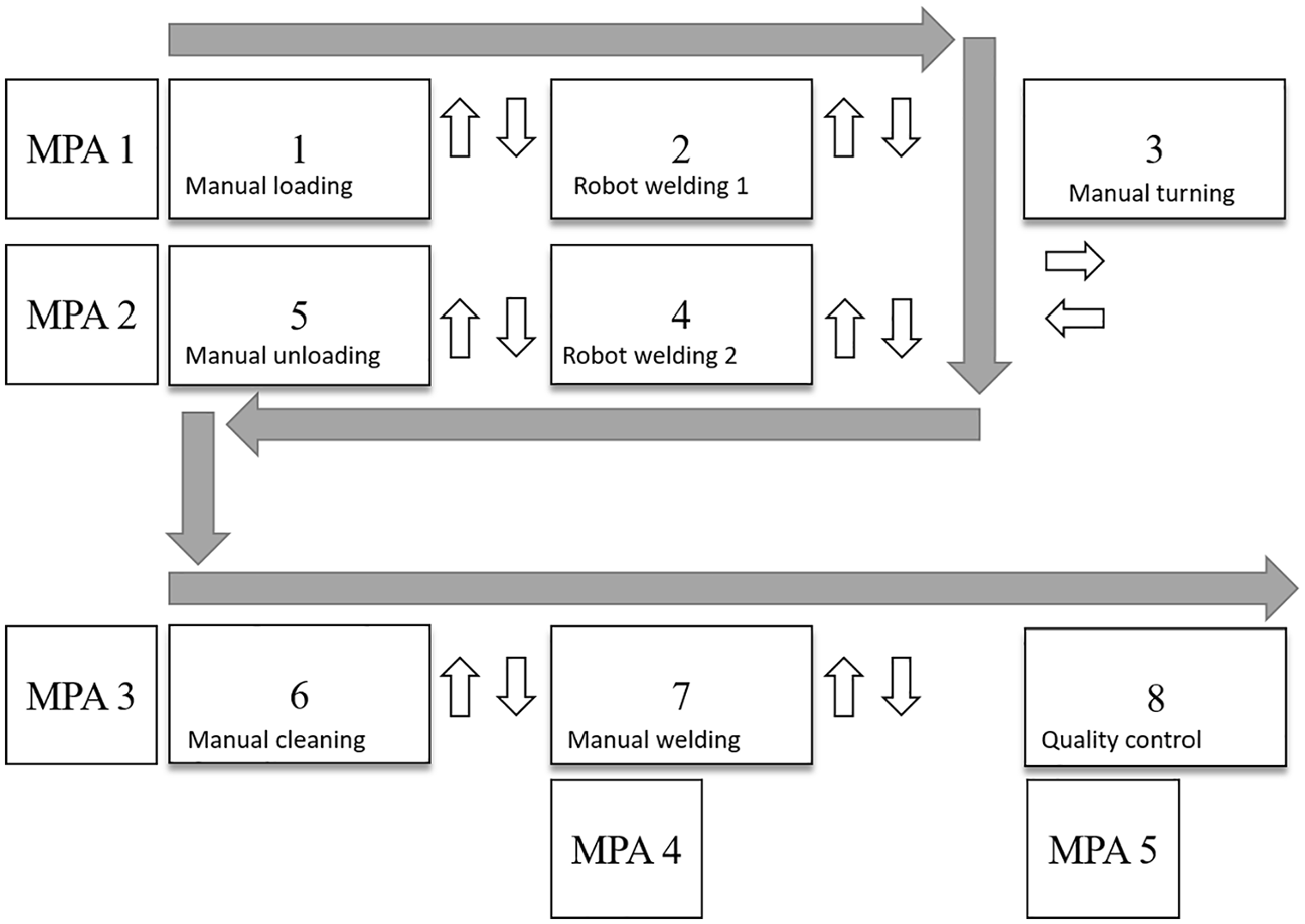
Conceptual model of production of electrical cabinets in Case A.
This stage includes defining scenarios for future implementation. For example, in Case A, scenarios are focused on meeting a 40% increase in demand and reducing lead time and buffer size by at least 10% and 15%, respectively. Case A involved three alternative machine layouts, and implementation of a conveyor for material handling, considering the factory floor space and production flows to meet increasing demand. The possible scenarios of Case B involved increasing production by 30% in 5 years or renewing the internal material handling systems because of the number of accidents and delays caused due to the use of manual forklift trucks. Then, throughput and different types of transport have to be considered in the conceptual models at this stage. Once the current and future states of the system and their conceptual models are defined, as well as clear project planning with some preliminary layout designs are on the table, it is time to move to the development stage.
Development: Now, the objective is to build, verify, and validate the simulation models of the production and logistics systems involved in and relevant to the layout design. Subsequently, these simulation models will be considered in an aggregated, holistic model of the entire system. In this model, different alternative layout designs can be tested to define specific parameters for constructing the final layout design. These parameters can be, for example, the size, shape, size of the departments and distances between them, as well as the throughput of products, lead times, buffer capacities, etc. Special focus must be placed on simulation models of production and logistics systems. An important aspect of this stage is the selection of simulation software. Frequently, manufacturing companies select simulation software based on the availability and expertise of the staff. The staff in Case A used ExtendSim version 9.2, including the genetic algorithm, and in Case B used the FACTS Analyser, including the non-dominated sorting genetic algorithm III (NSGA-III). Similar simulation software tools with integrated optimisation engines could be utilised for optimisation purposes. For example, Figure 3 presents the simulation model for the production of electrical cabinets in Case A. The model in Case A focused on maximising throughput and minimising lead time and work in progress. It considered different scenarios involving factory floor space and production flows, including machine layouts and a conveyor for material handling. The selection of the simulation software is also dependent on its optimisation engine. It should be ensured that the simulation software’s optimisation engine handles multiple conflicting objectives. The support of discrete-event simulation for this purpose can be key due to the complexity and size of the systems to analyse and the required material storage necessities. Manufacturing companies may rely on methodologies guiding staff on the development of simulation models.28,29
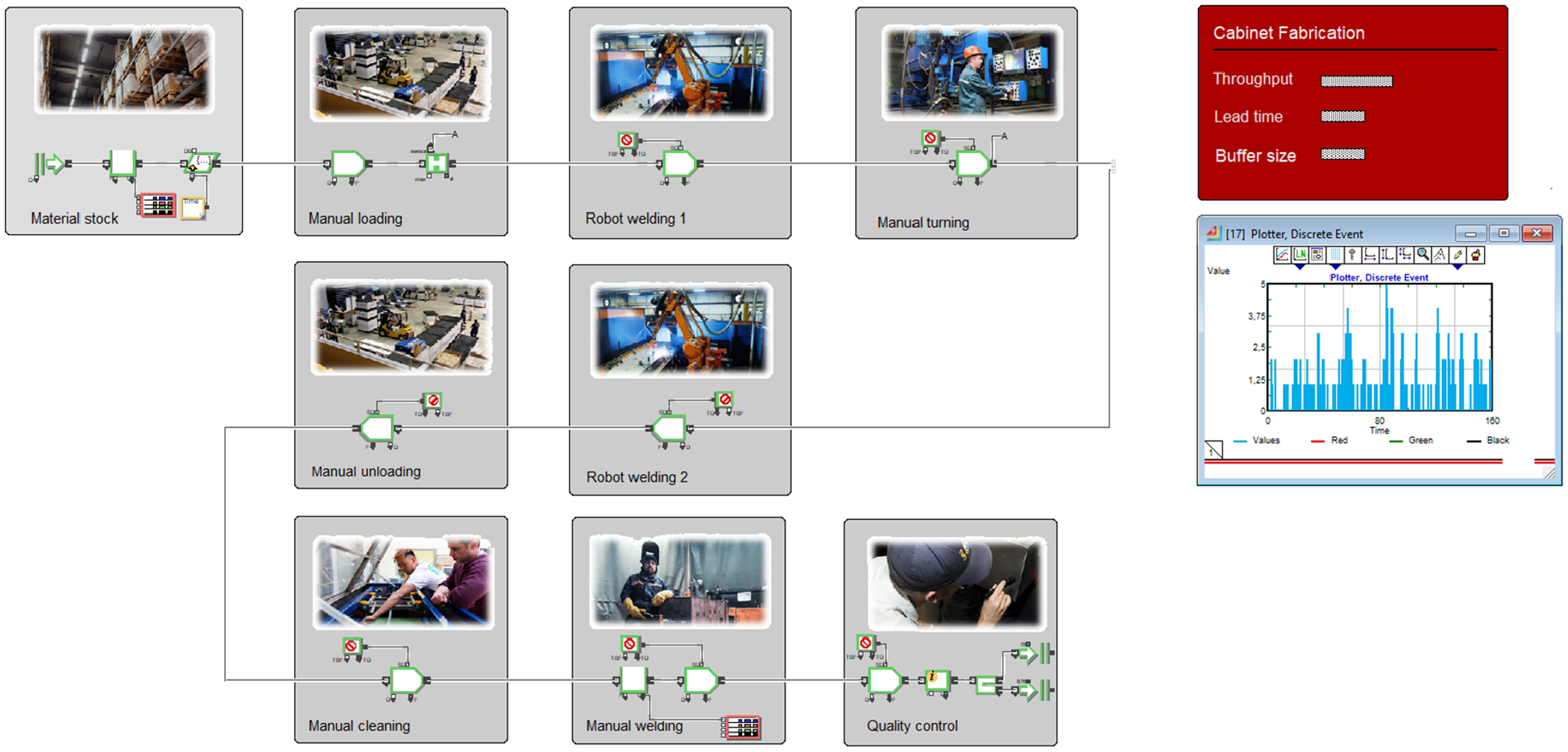
Simulation model for the production of electrical cabinets in Case A.
This model has to be verified and validated, which is usually done by comparing the simulation model with reality and analysing if the results are accurate enough for the study’s purpose. Once this is achieved, it is possible to analyse the model to find the weaknesses of the system and potential improvements. For example, identifying bottlenecks, the balancing problem of the assembly lines, and its shape distribution on the shop floor can be of great importance to picture the future shop-floor layout.30–34
Similarly, once the production system has been simulated to visualise the current state and possible improvements in the future state, the material handling system can be added or simulated independently. This depends on the complexity and size of the system for analysis. In Case A, the logistics systems could be added to the simulation model of the production of electrical cabinets. On the other hand, in Case B, the complexity of the assembly lines multiplied by the total number of lines (several of them were considered on the same facility layout) required the construction of simulation models of the logistics system independently. These problems (both production and logistics) can become significantly large (NP-Hard) depending on the size and complexity of the system. Simplifications or assumptions must be considered without compromising the accuracy of the results. For example, some assumptions can simplify the number of products and variants and work with product families instead.
Considering the nature of the previously simulated production and logistics systems (Figure 3), the layout type required for each area of the shop floor can be defined regarding fixed-position layout, functional layout, cell layout, and line or product layout. 35 As a starting point, a narrowed set of alternative scenarios, two approaches can be used to obtain a final set of optimal layout designs. One of them is the application of common sense in combination with the constraints defined at the first stage and refined during the second stage. This common sense and constraints should be revised at this stage, addressing questions such as (14):
Double-check building and site constraints, such as available area, height and location of the buildings, existing and possible input and output flows, accessibility, natural lighting, ventilation, electrical and hydraulic fitters, etc.
Fulfil the analysed requirements of production design, variable demand, the capacity of equipment, processes, lines, stores, and buffers, considering current and future variability of products and demand
Consider the analysed material handling system alternatives and their requirements (space required on corridors, paths, turning, loading and unloading, and charging and/or reparation areas)
Minimise financial demands, such as investments in equipment and material handling costs
The safety, comfort, and quality of work-life for employees
Once all the constraints are considered, limiting the amount of possible alternative layout designs, and production and logistics systems, a subsequent approach can be the incremental implementation of an improvement algorithm to improve the initial block layout proposed. Some of the tools that can be used to narrow the possible layout alternatives are exact methods, such as branch and bound and dynamic programming, heuristic algorithms, such as construction algorithms and improvement algorithms, meta-heuristics, such as genetic algorithms, tabu search, simulated annealing, ant colony optimisation and particle swarm optimisation, and mathematical optimisation modelling approaches.
However, by going through several layout design case studies, mathematical modelling is identified as an approach if resources with that level of competence are available on site. Mathematical modelling can also be helpful if the size and complexity of the layout design are between some boundaries (avoiding complex shop-floor shapes, significant numbers of flows of products or variants, and complex flows of transports, persons, or materials). Furthermore, the use of SBO can support the FLD decision process better than traditional methods if the complexity of the system is considerable, and if simulation experts in the organisation are involved in the layout project. To refine the final layout configurations, multi-objective optimisation can be applied to improve the conflicting objectives of the different simulation models by, for example, minimising the number of required transports and lead time while maximising or maintaining a certain throughput.
Once the production and logistics simulation model results and the results of some layout scenarios considering these production and logistics systems are obtained, we move to the evaluation stage.
Evaluation: This stage comprises the optimisation of the logistics and material storage systems that fulfil the requirements of the previously simulated production system. Thereafter, an aggregated holistic simulation model of the entire system can be built. This model represents the production system in an aggregated manner and adds the material supply and storage systems to optimise the objective parameters, such as area, throughput, storage, work-in-process, lead times, etc. This stage might require going back to the conceptual and analysis stages to complement missing data or changes in the conceptual designs until the final holistic model can be verified and validated. This holistic simulation model can be ‘placed’ on different layout designs to analyse the performance of the system. An example of the simulation model of the logistics system of Case B is presented in Figure 4.
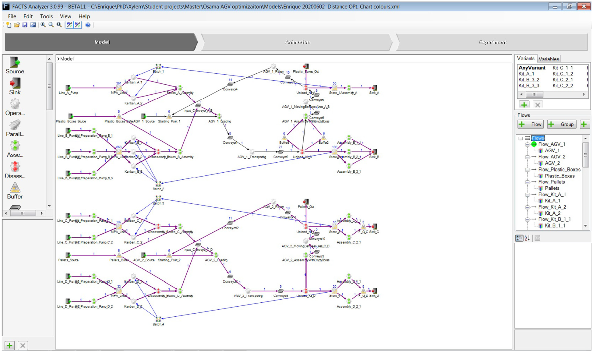
Simulation model of the internal logistics system in Case B feeding the assembly lines.
The objectives of the optimisation were the reduction of lead time, distance between departments, work-in-progress, buffer capacity, and number of transports. The main constraints are presented below.
Constraints
The main constraints identified and considered in modelling the problem in FACTS software are presented below.
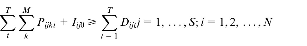
Demand satisfaction: The total number of delivered pallets or plastic boxes of each part to each station plus its initial inventory should satisfy the demand of each part at each station.
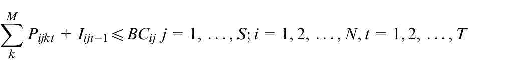
Space limitation: Owing to space limitations, the total number of available pallets or plastic boxes for each part should not exceed the maximum buffer capacity for that part in each station.
Vehicle Capacity: The total number of loaded containers in each vehicle should not exceed the maximum capacity of the vehicle.

Safety buffer: The available amount of each part at each station should not be less than a certain safety buffer.

There are additional details and assumptions included in the simulation model; however, owing to the complexity, it is not possible to show all the relationships in the form of mathematical equations. Nevertheless, the main constraints are mathematically presented for better clarification. The results of this optimisation are presented in Figure 5. At this stage, different alternative layout scenarios can have, for example, different locations, shapes, and sizes of some of the departments, input and output flows of material and products, aisles of workers and transports, etc. The results of the simulation models and the optimisation of comparing different alternative layout designs can then be analysed by managers and stakeholders in the last stage of the methodology – the conclusion.
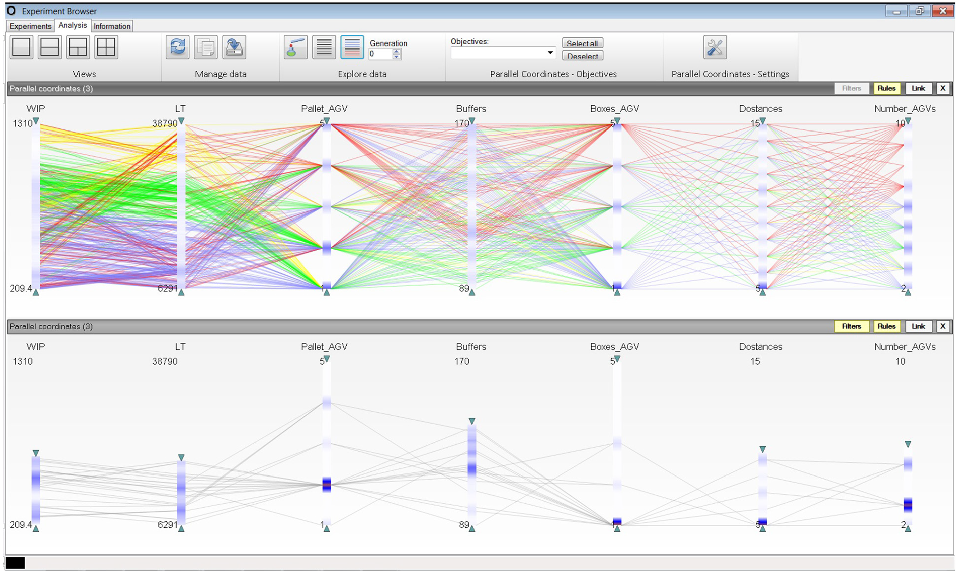
Parallel coordinates chart of the production and logistics optimisation in Case B.
Conclusion: The final stage involves evaluating the holistic simulation model and the optimisation results and analysing the parameters or key performance indicators of interest to perform a final selection of the best layout design alternative. Commonly, a Pareto front is used in these cases to evaluate the optimised solutions representing different layout alternatives. The Pareto fronts commonly obtained from the optimisation approach in the previous stage can be a useful tool, for example, by comparing the number of required transports against the lead time or work-in-progress. An example of Case B is presented in Figure 5, showing the optimisation results summarised in a parallel coordinated chart.
This chart shows the optimised maximum and minimum values of the work in progress (WIP), lead time (LT), number of automated guided vehicles (AGVs), the capacity of buffers, and distances between departments. This chart allows managers and stakeholders to analyse different optimised scenarios considering the different objectives and constraints. The implementation showed positive results in all stages of the methodology, especially for the project manager and his closest engineering team.
A key step when focusing on cost management is introducing the approximated budget descriptions of moving departments, machines, lines, etc., changing the transportation systems, or constructing new material preparation areas. Other aspects to consider are the feasibility of the solutions regarding implementation times and plans, for example, with questions like: Can an assembly line be shut down for 2 weeks to move to the new location? Is there enough space for the buffer of the assembly line to keep production running? How would those products and materials be transported during the two-week moving period? Finally, it is up to the managers and stakeholders of the project to choose the best optimised layout design that can handle the previously optimised production and logistics systems within the scope of the project.
Methodology verification and validation
The proposed methodology for FLD has been verified and validated through an in-depth industrial case study – case B, introduced in section 3. Verification is to ensure that the methodology is represented and explained properly, checking all the necessary steps for the design of facility layout, and the use of simulation and optimisation. This verification was done by focusing on three layout design projects of Case B, following them with the methodology and double-checking all the documentation and procedures. It ensured that all the detailed steps and simulation methods were defined properly in the methodology.
The validation procedure, to ensure that the methodology was represented and explained properly for its purpose (the design of optimised facility layouts), was performed using interviews with experts in the layout design domain, such as layout engineers from different manufacturing companies. In the second stage, various FLD projects were performed in Case B, in which an in-depth industrial case study for layout design was performed using this methodology, as presented in Figures 4 and 5. These projects focused on the design of the layout of one of the assembly lines, the design of the facility layout of a group of assembly lines, and the design of the layout of a shop floor, including machining, storage, and assembly lines.
Finally, the stages and steps of the methodology and their interconnections were analysed using the functional analysis resonance method (FRAM). 36 FRAM is a tool for designing, analysing, and managing a series of actions to represent them reliably and systematically, and in a well-defined format. The FRAM allowed the structured representation of the steps and stages of the methodology and helped identify critical activities that can have fatal repercussions if insufficient time or resources are allocated. With these three approaches, verification, in-depth case study, and FRAM, the methodology was considered valid.
Conclusion
This paper presents a literature review and analysis of challenges using SBO for FLD in production systems. To cope with these challenges, a multi-level methodology is proposed for the design of optimised layouts considering production and logistics constraints. The proposed methodology is intended to serve as a project planning approach for considerably complex layout designs requiring the use of SBO. This paper strongly emphasises the awareness and suggestion stages of the project, in which the importance of the definition of the aim and objectives in coordination with the vision and strategy of the company, as well as with an ideal future state, are key to understanding the current and future states and expected solutions. This is crucial for the success of the development of simulation models.
Using the perspective of complex production systems, especially focusing on manufacturing shop floors, the proposed methodology for layout design combines well-known layout procedures, such as Reed’s and Apple’s, and Muther’s plant layout procedures, with additional well-known simulation methodologies, such as Bank’s and Law’s simulation steps. These procedures are especially used in the suggestion and development stages of the production and logistics systems to be considered in the shop floor layout. However, it is usually not possible to model everything at once due to complexity, software, and resource limitations. Therefore, the aggregated models are considered for the simulation of the logistics and production systems, as well as for the simulation of final alternatives of the layout designs in an iterative manner.
To conclude, the main contributions of implementing this methodology for layout design are to help identify the required involvement of the different levels in the vertical chain of people related to the production layout, highlight the critical steps in a methodology regarding project planning, simulation, and data collection processes, and the design of the optimised logistics and production systems to be considered in the final layout design alternatives. These benefits are connected to the challenges of SBO (section 2) regarding the complexity of the systems, the noise of the data, the search for local and global solutions, evaluation of optimal solutions, people’s competence, and modelling process and technology. However, the challenges of FLD (complexity, dynamicity and randomness, cost, integration, process, and safety) can be significantly met by implementing this methodology with SBO with support in planning, task division, and structured data collection. Regarding the challenges of process and safety, it would depend on the individual application study, and further research might be required for this analysis. Finally, this methodology has been validated, and has demonstrated that it can serve managers and stakeholders when working with complex systems, considering the local management, engineers, and technicians involved in this type of layout design project. Future work includes implementing the proposed methodology in additional cases – for example, in small-size manufacturing systems or in the healthcare sector.
Footnotes
Appendix
Acknowledgements
We would like to express special thanks to the Swedish Knowledge Foundation and to the industrial partners for research funding and for the opportunity to develop this research with them. We would also like to thank the IPSI Industrial PhD Research School in Informatics at the University of Skövde, and Xylem Water Solutions Manufacturing AB for their initiative to start this research project and their continuous support.
Declaration of conflicting interests
The author(s) declared no potential conflicts of interest with respect to the research, authorship, and/or publication of this article.
Funding
The author(s) received no financial support for the research, authorship, and/or publication of this article.