
Abstract
The free bending method is the simplest method among the tube bending processes without the use of a die. Despite the simplicity of the process, there is no proper control over the geometrical tolerance of the product. The loading path or in other words the bearing movement mechanism is one of the effective factors on product geometry. In this paper, a finite element simulation has been carried out to investigate two different bearing movement time-paths (synchronous and asynchronous mechanisms); then, the results have been verified with experimental tests. The thickness distribution in different directions, ovality, bending radius, and applied forces on the bearing and the tube for both bearing movement mechanisms are the main results of this paper. The amplitude of thickness change in both mechanisms was equal. But there is a uniform trend in variation of thickness distribution in synchronous mechanisms. So, better geometrical quality of products is expected in this mechanism. On the other hand, because of uniform force distribution with tube movement in the bearing and tube, the stability of the asynchronous mechanism is higher than the synchronous mechanism.
Introduction
The tube bending process is widely used in a variety of industries such as automotive, petrochemical, construction, home appliances, decorative items, etc. 1 Due to its sheet nature, the mentioned process is similar to processes such as the cold roll forming 2 and deep drawing processes, 3 and has common defects such as thinning, wrinkling, and spring-back. Therefore, it is important to choose an appropriate method for bending the tube. Different traditional tube bending methods require the use of a proprietary die for each tube size. 4 So, in these methods, the accuracy of the created bending is influenced by the die parameters such as die geometry. 5 The main idea of free bending was raised by Murata et al. 6 They presented the “MOS” method for bending without a proprietary die. In this method, the tube was driven into a movable die and bent by changing the position of the movable die. The improved MOS method is called free bending. In free bending methods, process arrangements are planned to bend a wide range of tubes using only one die in various bending sizes and radiuses. 7 One of the benefits of free bending is to produce a tube with a continuous bending radius without any straight area in the tube. 8 Producing the 3D and spline tubes is one of the special features of this process. 9 Also, the free bending method has high controllability by Computer Numerical Control (CNC) because of the type of mechanisms. 10 Three different movement mechanisms in free bending are different in a die connection type. The connection types comprise free, tangential, and spherical joints in the non-die bending process. In the free connection, only the die position in two movement directions is under control. In this connection, there is no control over the change of die angle. In the tangential connection type, a spherical surface is added to the die sequence so that at any given moment, the die sequence, which is an internal cone, is tangent to the surface of the spherical part. Movement range and tipping angle can be controlled by this mechanism. In the spherical connection type, both the parts before and inside of the die are spherical. The use of a third connection allows for greater control over the movement of the die. 11 In bending with the free connection, the movement mechanism is simple but with less controllability. In this paper, due to the low cost and simplicity, this kind of connection was used.
There are a lot of reports on the free bending process. Goto et al. 12 bent the tube freely using a fixed, and a movable die separately. In this mechanism, a hexapod table with six degrees of freedom and an electro-hydraulic servo control system were used to control the motion of the movable parts. In this study, it was shown that the proposed mechanism could produce three-dimensional non-straight section tubes. Cheng et al. 13 investigated the effect of the thickness-to-diameter ratio on the free bending of the tube experimentally, analytically, and numerically. It was shown that decreasing the thickness to diameter ratio makes the stress and strain distribution more uniform in the bent tube. Also, in two zones, one at the beginning of the tube entry into the die and the other at the end of the tube exit from the die, ovality, and strain distribution change undesirably. In the analytical model presented in this paper, stress distribution and neutral layer displacement were well predicted. Chatti et al. 14 presented a method for 3D bending of the tube and symmetric and asymmetric profiles. The proposed method employs three rollers and one movable die. It was demonstrated that using a removable die in bending has a significant effect on reducing process defects. Li et al. 15 by numerical and experimental study of free bending, showed that continuous bending with a maximum bending radius ratio of 1.7 can be made for tubes with symmetric and asymmetric cross-sections. The bending ratio was defined as a ratio of the bending radius to the outer diameter of the tube. Gantner et al. 16 studied free bending in a rectangular section by using both the finite element and the analytical methods. The proposed mechanism consists of eight guide rollers and four rollers as bending dies. In this mechanism, the desirable bending radius is obtained by changing the angle of four bending rollers. They presented relationships that predict the bending radius value based on the adjustment parameters of the machine. Guo et al. 11 showed that the conventional bending die design has some drawbacks because of unstable motion. They suggested a plan based on a spherical connection in which the bending die would be more controllable. With their proposed design, bending with a ratio of 3 is possible. In their study considering the slab method, they obtained stress and strain distribution in the bend section and showed that in areas at the beginning and the end of the bend, they were more intense and non-uniform stress and strain distribution. Guo et al. 17 analytically investigated the effect of machine adjustment and control parameters on the material correction factor (Km) and the coefficient of clearance (Kc) in bending of the Copper tube using a spherical connection of the bending die to the guider. They showed that proper selection of tube feed speed, clearance coefficient, material coefficient, and adjustment parameters of the machine plays an essential role in producing high-quality bent tubes. Hudovernik et al. 18 evaluated the amount of torque required in the Torque Superposed Spatial (TSS) bending method for square sections by experimental and finite element approaches. Also, distributions of the stress, the plastic strain, and elastic strain were studied numerically. Gantner et al. 7 showed empirically that in the free bending method, the continuous bends could be obtained with acceptable accuracy, and also the relation between the amount of movable die displacement and the bending radius is linear in this process. Hermes et al. 19 introduced the Incremental Tube Forming (ITF) method. This method is a combination of free bending and spinning processes. In this method, three rollers are first used to change the tube diameter. The tube is bent to the desired radius by a roller that can move on a plane, in the next forming stage. Liang et al. 20 experimentally studied the spring-back phenomenon in the flexible 3D stretch bending process. In this method, the tube was bent by dies simultaneously at several points while it is in the tensile state. They showed that for accurate 3D bending, both displacement and rotation along two axes are required. Also, the proper position of the bending dies causes a reduction in the spring back and eliminates the need for applying tensile force in this process. Staupendahl and Tekkaya 21 presented an analytical and numerical model to investigate the effect of torsional and bending torque on bending force and spring-back in the non-circular cross-section TSS bending process. It was shown that when the cross-section is asymmetric, the shear strain distribution in the bending section changes linearly.
As described earlier, different connection types have been proposed in previous studies for bending without die, each of which has its limitations. These connections have been proposed to eliminate the limitations and defects of the free connection type, but lead to an increase in process complexity and cost. However, this level of complexity is not essential in many applications. The free bending with a free connection type is interesting because of its low cost and simplicity. In this paper, considering the simplification and the flexibility of the bending process, two mechanisms of the bearing movement in the free bending process with a free connection type are presented. For this purpose, the effect of the loading path of bearing on the forces, defects, and geometrical shapes created in the free bending is investigated. Two motion mechanisms for free bending are proposed and operational parameters such as thickness distribution, ovality parameter, bending radius distribution, and forces applied to the tube and also applied to the bearing for both motion mechanisms are compared.
Materials and methods
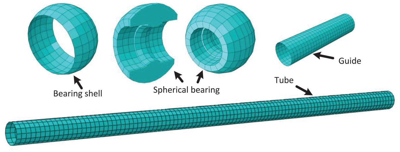
In this study, the effect of two synchronous and asynchronous motions of bearings was investigated on the geometrical defects and process forces. Aluminum 6061 and Copper 12200 were used as the tube materials to obtain a deep insight into the process. The numerical approach was exploited for this purpose. Abaqus finite element commercial software was used for the numerical study. Numerical results were validated through the experimental results. Figure 1 shows the geometrical model of free bending components.
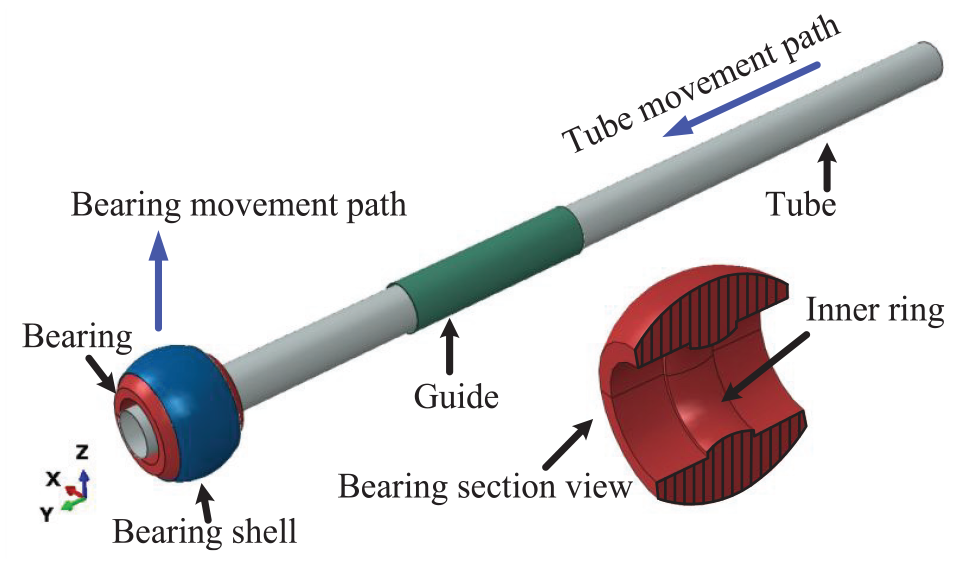
Free bending components.
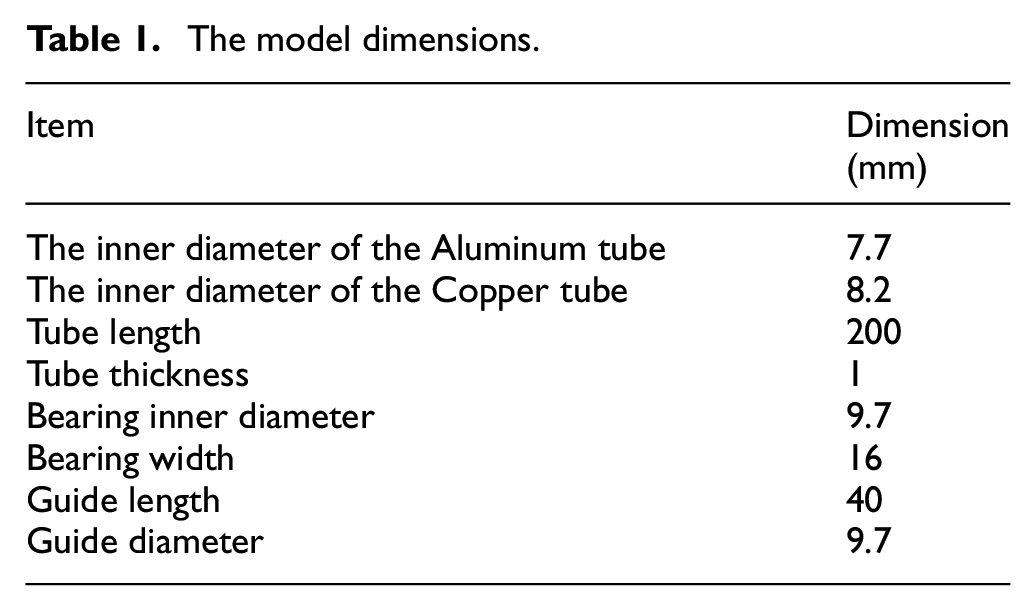
Different simulation methods consist of the dynamic explicit and the dynamic implicit are applicable for this study. Simulations were performed by using both of them, but insignificant differences were observed in the results. The dynamic implicit simulation is a time-consuming method and has an unstable result. Therefore, the dynamic explicit method was selected for the numerical simulation. The tube was modeled as a deformable shell. The guide and the bearing shell were considered rigid parts. A solid deformable model was used to consider the motion of the bearing due to the movement of other bearing components. Table 1 shows the dimensions of the model.
The model dimensions.
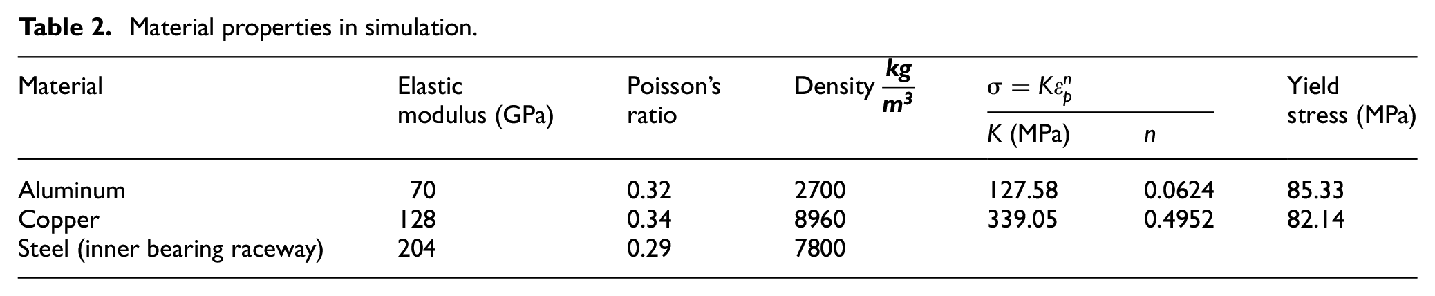
Materials properties were experimentally determined and were listed in Table 2.
Material properties in simulation.
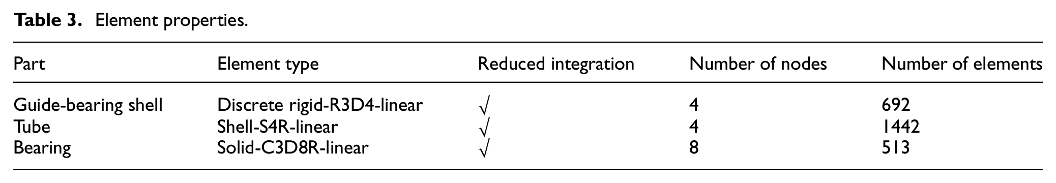
Element properties, according to Table 3, were chosen for the simulation. The number of elements was selected so that the results were independent of the mesh size. For this purpose, the simulation was repeated for the different numbers of elements. The number of elements was selected in such a way to strain energy variations was less than 5%. The meshed model was shown in Figure 2.
Element properties.
The meshed model.
All degrees of freedom of the guide were constrained. The contacts between the mated surfaces were defined as the surface-to-surface contact with a friction coefficient of 0.05. This value for the coefficient of friction was considered according to the pre-lubrication, and the material of tubes and bearing raceway. This value for the friction coefficient was used in a similar situation in Guo et al. 11 The tube and the bearing shell movements were according to the movement pattern shown in Figure 3. According to Figure 3, in the asynchronous mechanism, the bearing is first moved as specified and the tube displacement is then applied. In the synchronous mechanism, both the tube and the bearing movements are linearly done together. The value of the parameter “a” in Figure 3 is considered to be 5, 7.5, 10, and 12.5 mm for the asynchronous motion and 2, 3, 4, and 5 mm for the synchronous one.
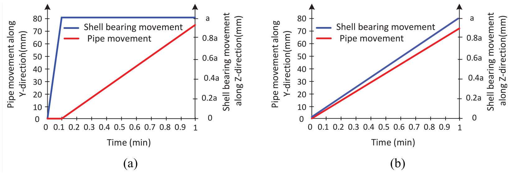
Applied displacement on the tube and bearing shell in the (a) synchronous, and (b) asynchronous motions.
Experimental test
An experimental setup was designed and fabricated according to Figure 4 to validate the accuracy of the numerical results. In this setup, a spherical bearing was used instead of a die. To precisely position the tube, a position ring was mounted compressively inside the bearing. The bearing was embedded in a plate. The possibility of movement in one direction was provided for the bearing and the plate was embedded in the machine by using two rails. The position of the bearing was controlled by an adjusting screw. The pipe was pre-lubricated before the bending process with SAE 20 oil; however, there was no lubrication during the bending process. Figure 5 shows the experimental setup.
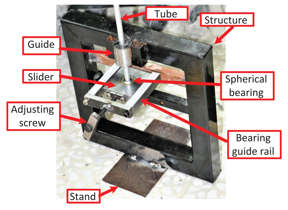
Uniaxial bending machine and its components.
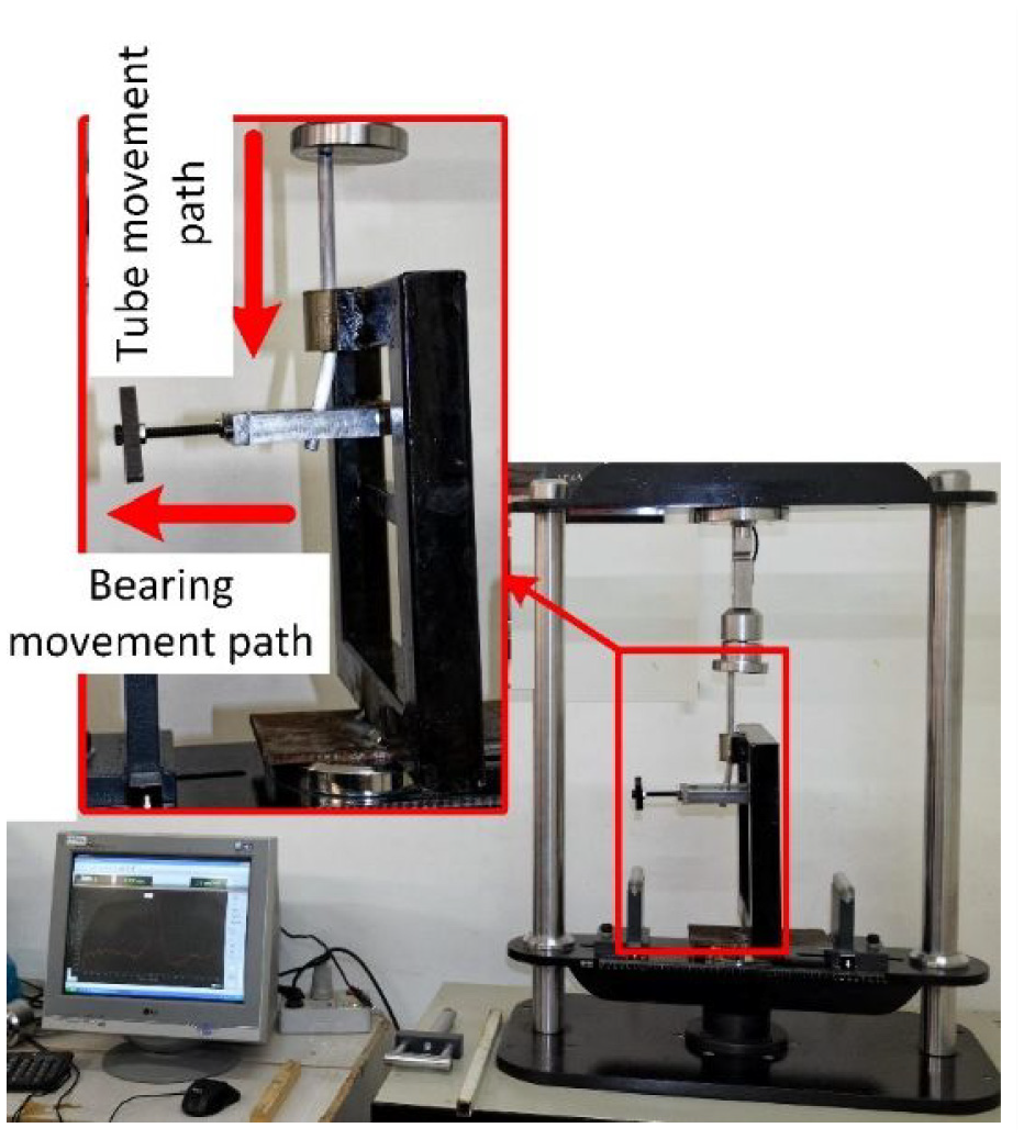
The experimental setup.
The bending radius was measured using a profile projector with an accuracy of 0.001 mm. The tubes were cut by a wire-cut machine to measure thickness distribution and the ovality parameter. These parameters were measured by a caliper with a 0.01 mm resolution.
Experimental design and verification of simulation
The simulation was carried out for both Aluminum and Copper material with two synchronous and asynchronous motions, according to Tables 4 and 5. Experimental tests were done for the asynchronous motion mechanism for verification of simulations. As can be seen in Table 4, the highest percentage of bending radius error in the simulation compared to the experimental work is 15.6%. It can be justified by paying attention to the assumptions of tube diameter uniformity and its perfect straightness in the simulations. This is while any tube has a certain amount of curvature and inconsistency in its diameter in the real-world application.
Table of simulation for the asynchronous mechanism with experimental verification.
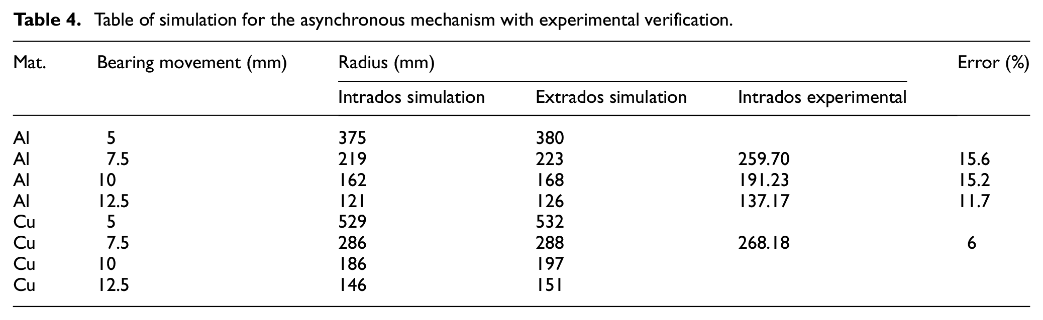
Table of simulation for the synchronous mechanism.
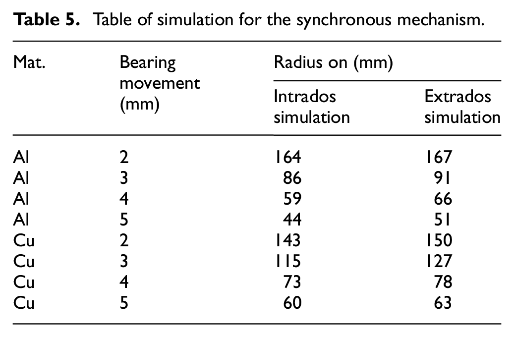
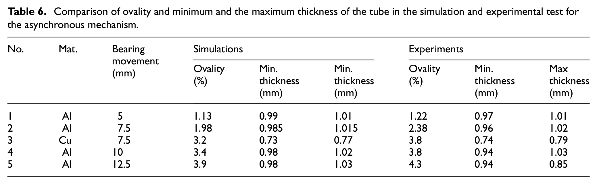
Figure 6 shows experimental samples. The maximum and minimum tube thicknesses, as well as the ovality determined from the experimental tests and simulation for Aluminum and Copper tubes, are shown in Table 6. As can be seen, the maximum error between the experimental and numerical results is obtained as 4.3%.
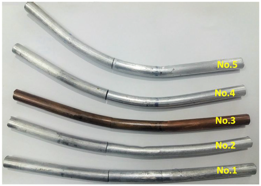
Experimental samples.
Comparison of ovality and minimum and the maximum thickness of the tube in the simulation and experimental test for the asynchronous mechanism.
Result and discussion
As mentioned earlier, the effect of the movement mechanism on geometrical defects in free bending with free joint type has been investigated. For a better analysis of the results, the main areas of forming in the synchronous and asynchronous mechanisms are considered according to Figures 7 and 8.
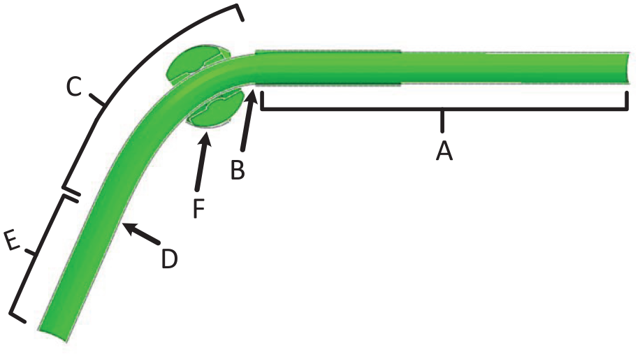
The main areas in the synchronous mechanism.
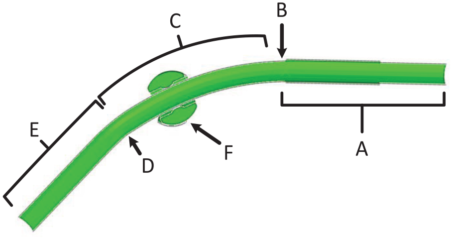
The main areas in the asynchronous mechanism.
Figure 9 shows the simulation results for the synchronous mechanism at different times. As can be seen, the synchronous displacements of the bearing shell and the tube causes the bearing to rotate and the tube to bend.
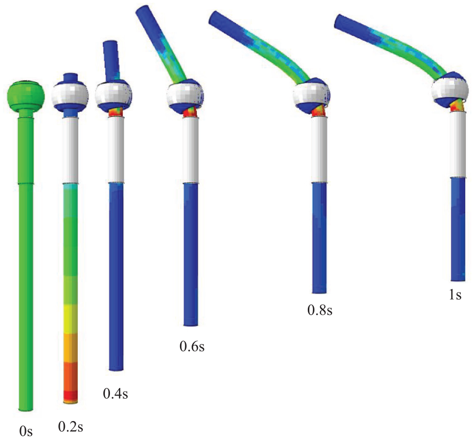
Simulation steps at different times in the synchronous mechanism.
Experimental results were measured after the tube unloading. For this purpose, after the tube passed through the deformation zone, the necessary time for spring-back was considered to match the simulation with the experimental conditions.
The influence of loading path on thickness distribution
The defined path was considered on the inner radius in the longitudinal direction in agreement with Figure 10. The thickness distribution and other parameters were investigated on this path. Figure 11 shows the effect of the time-movement path of the bearing and the tube on the thickness distribution along the longitudinal direction within the inner radius. The bearing movement was abbreviated as B.M in this figure. By comparing Figure 11(a) and (c) and (b) and (d), in both mechanisms, the D area, which is the end of the guide at the beginning of the bend, initiates the thickness changes. Also, in the asynchronous motion mechanism, the maximum thickness occurs in this area. Consequently, the corner radius at the end of the guide affects the thickness distribution in the asynchronous mechanism. In the synchronous mechanism, the thickness changes linearly, whereas, in the asynchronous, the changes are not uniform. Zone E is the area of the tube which is in the bearing at the beginning of the bend. Zone C is the area of the tube that moves inside the bearing. As can be seen in both mechanisms, the thickness variation is increased by increasing the bearing displacement. The B area of the tube is at the end of the guide at the end of the bend. In the synchronous mechanism, zone B has the most changes in thickness, so the corner radius at the end of the guide affects the thickness distribution in the synchronous mechanism.
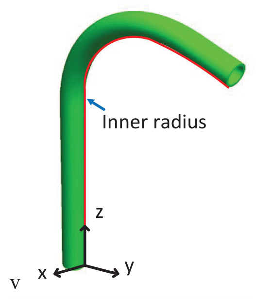
The path defined on the inner radius of the tube in the longitudinal direction.
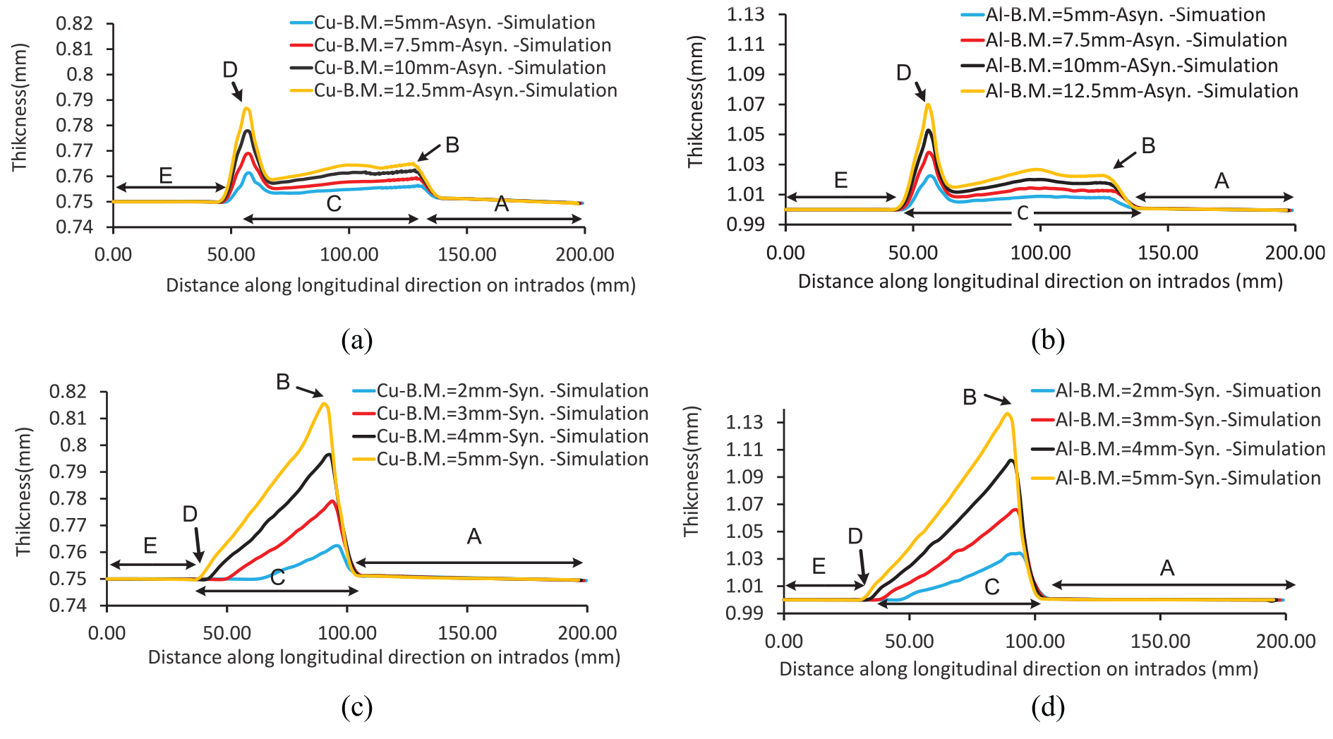
The influence of time-movement path of the bearing and the tube on thickness distribution in inner radius along longitudinal direction: (a, b) asynchronous mechanism and (c, d) synchronous mechanism.
Figure 12 shows the influence of the time-movement path of the bearing and the tube on the thickness distribution along a longitudinal direction within the outer radius. By comparing Figure 12(a) and (c) and (b) and (d), the trend of thickness changes is the same as the thickness changes within the inner radius. In the D zone, the synchronous mechanism shows higher thickness variations than the inner radius, indicating the importance of the outer corner radius at the end of the guide. The preliminary displacement of the bearing in the asynchronous mechanism causes initial nonuniformity in thickness distribution. So, the uniformity of thickness distribution in the asynchronous mechanism is smaller than the synchronous mechanism. The uniformity in thickness distribution leads to tighter geometrical tolerances in the final products.
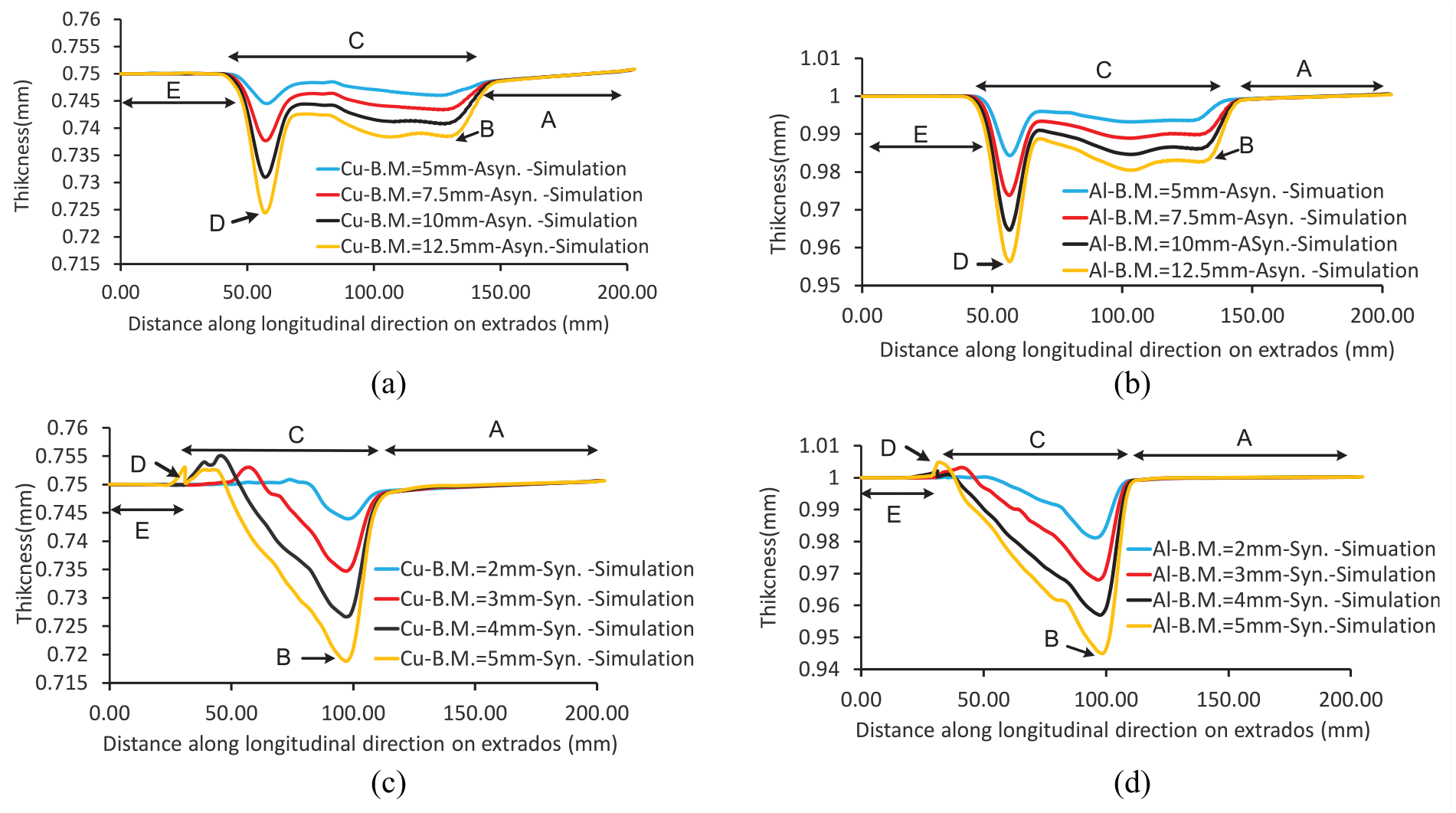
The influence of time-movement path of the bearing and the tube on thickness distribution in the outer radius along longitudinal direction: (a, b) asynchronous mechanism and (c, d) synchronous mechanism.
The influence of the loading path on the geometric shape in the inner radius
Figure 13 shows the effect of the movement mechanism path of the bearing and the tube on the geometric shape of the inner radius. As can be seen in both motion mechanisms, the amount of bending radius decreases linearly with increasing the bearing displacement. Also, by comparing the geometrical shape in the specific bearing movement for both Aluminum and Copper material, it can be concluded that a smaller bending radius was formed in the Aluminum tube with the same movement of the bearings in both mechanisms.
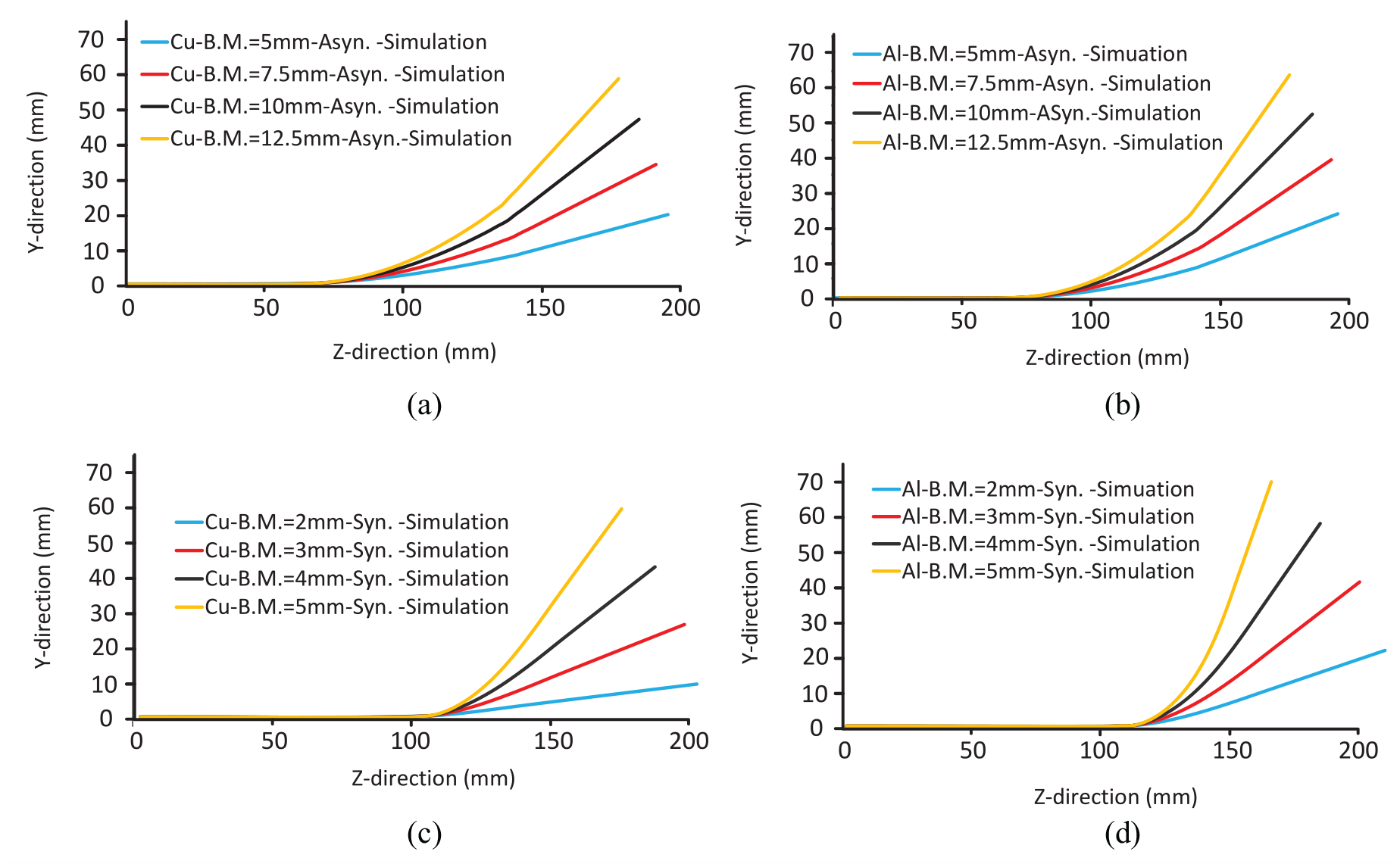
The influence of the time-movement path of the bearing and the tube on the geometrical shape in the inner radius along the longitudinal direction: (a, b) asynchronous mechanism and (c, d) synchronous mechanism.
Figure 14 shows the effect of the movement mechanism on the geometrical shape along the longitudinal direction of the tube. As can be seen in this figure, at a specified displacement value, a smaller bending radius can be created in the synchronous mechanism in comparison with the asynchronous mechanism. The difference in the arrangement of the components between the synchronous and asynchronous mechanisms including the guide and the bearing has caused this issue.
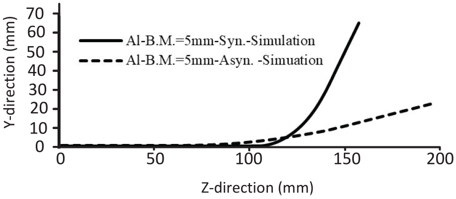
Influence of motion mechanism on geometric shape along longitudinal direction related to 5 mm bearing displacement.
The influence of the loading path on the geometric shape in peripheral cross-section
A path along the peripheral direction was defined according to Figure 15 to investigate the mechanism of the bearing movement on the geometrical shape of the peripheral section. As shown in Figure 16, the maximum thickness variation occurs in the D and B zones for the synchronous and asynchronous mechanisms, respectively. Hence, the paths in zones D and B were defined for synchronous and asynchronous mechanisms, respectively. As shown in Figure 16, the movement mechanism for both Aluminum and Copper materials don’t have a significant effect on the thickness distribution in the peripheral direction. The difference in thickness value in Figure 16(a) to (d) is due to the difference in the bending radius between the synchronous and asynchronous mechanisms. As can be seen in Figure 16, the distribution of wall thickness is not symmetrical. It was occurred because of a nonuniform clearance contact between the tube and the inner ring.
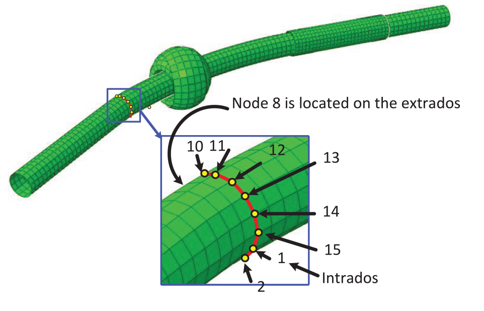
The defined path in the peripheral direction.
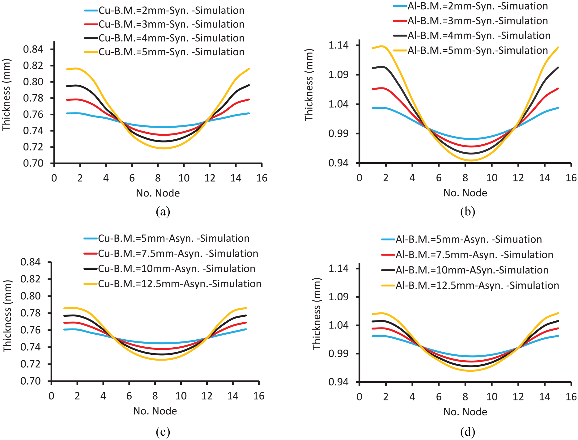
Distribution of thickness on the peripheral path for cross-sections having maximum thickness variations: (a, b) asynchronous mechanism and (c, d) synchronous mechanism.
The distribution of equivalent plastic strain in the peripheral path is shown in Figure 17. Points 1 and 16 are on the intrados radius of bending, and point 8 is on the extrados radius of bending. As can be seen in the asynchronous mechanism, the equivalent plastic strain on the extrados radius is higher than on the intrados radius. It is completely vice versa in the synchronous mechanism So, in the asynchronous mechanism, more defects may occur at the extrados radius whereas the synchronous mechanism is vice versa.
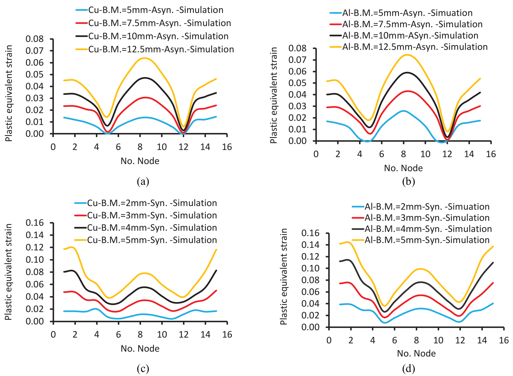
Distribution of the equivalent plastic strain on the peripheral path of cross-sections having maximum thickness variations: (a, b) asynchronous mechanism and (c, d) synchronous mechanism.
The influence of the loading path on the bearing force
In Figure 18, the effect of the movement mechanism on the bearing force is depicted for both Aluminum and Copper tubes. As can be seen, the forces are more uniform in asynchronous motion than in synchronous one. The average forces in synchronous mode are about four times of asynchronous mode. The forces in the synchronous mechanism are in the oscillating form. By increasing the bearing movement in all cases, the force on the bearing has increased. It can be concluded that in the synchronous mechanism, the working conditions are more difficult and the force applied to the spherical roller bearing is higher. The load is more uniform in the asynchronous mechanism because of the less spherical bearing movement in this mechanism than the synchronous mechanism.
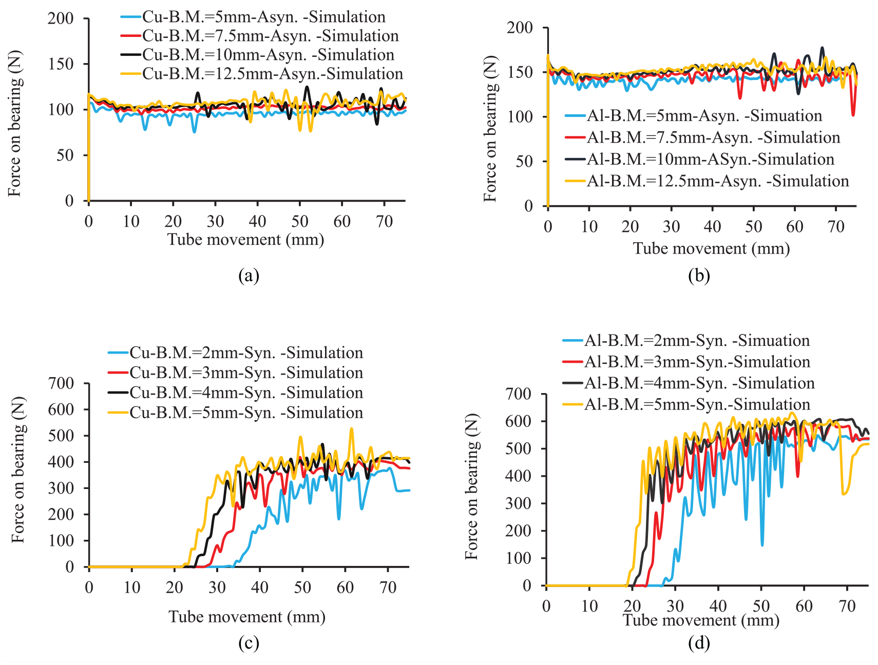
The time-movement path effect of bearing and tube on forces on the spherical bearing: (a, b) asynchronous and (c, d) synchronous.
Effect of the time-movement path of bearing and tube on forces on the tube
Figure 19 shows the compressive forces applied to the tube to push the tube inside the bearing. In Figure 19(a) and (b), the measured forces in the experimental tests are shown in comparison with the forces obtained from the simulation. As shown in this figure, trends of force variation in the numerical and experimental results are well matched. Also, the average forces in the asynchronous mechanism are higher than that of the synchronous one. There is an opposite trend for the forces applied to the bearings. As shown in Figure 18, with increasing the bearing movement, the forces applied to the bearings are increased. This is due to the increasing in the percentage of displacement of the deformation force by bearings.
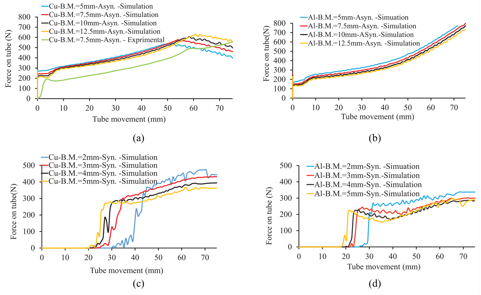
The time-movement path effect of bearing and tube on forces on the tube: (a, b) asynchronous and (c, d) synchronous.
As shown in Figure 19, the changes in force applied to the tube in the synchronous mechanism are greater than the asynchronous mechanism. This phenomenon creates a vibration on the bearing in the synchronous mechanism, which makes the bending process more unstable and difficult to control.
Conclusion
In this paper, the motion mechanisms of the die in the die-less bending process were investigated on the product geometry and the bending forces. Two synchronous and asynchronous movement mechanisms for the tube and the bearing were considered. Based on the numerical and experimental results, the following conclusions were obtained.
The thickness distributions along the longitudinal path in the inner and outer radius were similar in both synchronous and asynchronous mechanisms. But in the synchronous mechanism, thickness distribution in the outer radius, especially at the beginning of the bend, was different from the thickness distribution in the inner radius and involved more variations.
The tube thickness distribution varied linearly and non-linearly for the synchronous and asynchronous mechanisms, respectively.
In the synchronous mechanism, there were variations in the thickness of the bending end area; whereas in the asynchronous mechanism, the maximum curvature occurred in the primary bending area.
In the asynchronous mechanism, the outer radius had a higher maximum equivalent plastic strain than the inner radius, whereas there was an opposite trend in the synchronous mechanism.
In the asynchronous mechanism, the forces acting on the bearing had a higher amount and less variation than the same parameters in the synchronous mechanism. The force fluctuation on the bearing in the synchronous mechanism made the mechanism less stable than the asynchronous one.
The forces acting on the tube in the asynchronous mechanism were higher than that of the synchronous one and had fewer linear changes.
Footnotes
Declaration of conflicting interests
The author(s) declared no potential conflicts of interest with respect to the research, authorship, and/or publication of this article.
Funding
The author(s) received no financial support for the research, authorship, and/or publication of this article.