
Abstract
The double-layered tube hydro bending method is proposed to solve the difficulties encountered in manufacturing ultra-thin-walled elbow tubes by traditional bending processes. The effect of internal pressure on the section flattening, the wall thickness distribution, and the bending defects are investigated. The specimen consists of an outer tube made of carbon steel and an inner tube made of stainless steel, with the thickness ratio of outer to inner layers equal to 10. The expression of the yield pressure of the double-layered tube is derived from theoretical analysis. In addition, the mechanism of the wrinkling and stabilizing of the inner tube is clarified with the help of finite element analysis. It is shown that the stability of the inner layer during bending is improved with internal pressure increasing. The wrinkling could be avoided when the internal pressure exceeds 0.2 times the yield pressure. The maximum non-circularities of the inner and outer layers under the yield pressure are only 3.3% and 2.5%, respectively. Besides, the thickness distributions of two layers along the bending line are very similar, the positions of maximum thinning of the outer and inner layers are all located at an angle from the symmetrical section. The wall thickness of two layers decreases with increasing internal pressure. It is proved by the experiments that the double-layered tube hydro bending method is feasible for manufacturing the ultra-thin elbows.
Introduction
Ultra-thin-walled tube elbows are widely used as key components of transporting and pressurizing piping systems in civil airplanes and large rockets. In general, the tube with the diameter-to-thickness ratio (d/t) greater than 150 is referred to as the ultra-thin-walled tube. For ultra-thin-walled tubes, wrinkling and section distortion often occur at the early stage of traditional bending processes owing to its low stability to the axial compressive stresses.1–3
Numerous researches have been undertaken to prevent bending defects, especially wrinkling in the traditional thin-walled tube bending processes, such as numerical controlled draw bending with rigid mandrel,4–6 push bending using flexible elastomer mandrel,7,8 stretch bending9,10 and concrete filled bending. 11 However, it was found that difficulties arose when an attempt was made to adopt a larger diameter-to-thickness ratio. Trial and error is frequently required to avoid wrinkling, excessive thinning and flattening. 12 To the best of our knowledge, the results revealed that the maximum value of the diameter-to-thickness ratio of thin-walled tubes could not exceed 100 with these traditional bending processes.2–4
The hydroforming process provides a simple alternative to manufacture such thin-walled tube elbows. 7 It was shown by the single-layered hydro bending test on stainless steel tubes that when the relative bending radius R′ (ratio of the neutral bending radius to the diameter of the tube) equaled seven, a maximum value of the diameter-to-wall thickness ratio of 52 could be observed. 13 By employing the hydraulic support instead of rigid mandrel, the computer numerically controlled (CNC) single-layered hydro bending process of thin-walled tubes was developed. The results showed that the bending limit was improved and a demonstrating steel thin-wall tube elbow with R′ = 1.6 and the maximum d/t of 45 was presented. 14 Moreover, the results from the single-layered hydro bending experiment of aluminum alloy thin-walled tubes showed that when R′ = 5, the maximum diameter-to-wall thickness ratio was 63. 15 It was also shown, from a series of single-layered bending tests on mild steel thin-walled tubes, that when R′ = 15, the maximum diameter-to-wall thickness ratio could not be more than 100. 16 As mentioned above, the maximum value of d/t could not exceed 100 with various traditional bending processes.
To solve this problem, a new double-layered tube hydro bending method for manufacturing the ultra-thin-walled elbow components was developed. 17 Its basic procedure consists of:
wrapping the ultra-thin inner tube with a thicker outer tube;
sealing and pressurizing the double-layered tube with a liquid medium;
double-layered tube bending with internal pressure support;
separating the outer layer from the elbow.
By employing the outer thicker tube, the ultra-thin-walled tube was evidently stabilized with a sufficient internal pressure. The effect of the outer tube thickness on stabilizing the inner tube was analyzed. A sound stainless steel ultra-thin-walled elbow, with the diameter-to-thickness ratio of 182, was successfully manufactured. It was found that this new method is feasible to manufacture the ultra-thin-walled elbows, especially in a lower volume for piping systems in the aerospace industry.
The purpose of this work is to clarify the deformation behaviors of the double-layered tube bending with different levels of internal pressure and their effects on the bending results of the ultra-thin-walled elbow components. The influence of internal pressure on the cross-section deformation, wall thickness distribution and bending defects of the double-layered tube are discussed. Moreover, the mechanisms of wrinkling and stabilizing of the inner layer are analyzed through numerical simulation.
Specimen and materials
The double-layered tube specimen was prepared by wrapping the ultra-thin-walled tube with a mild steel outer thicker tube, which is a temporary assistant and will be removed after the hydro bending process. Then the double-layered tube was sealed with end caps by welding at the two ends, as shown in Figure 1. The inner tube is made of stainless steel, with an outer diameter of 182 mm, a wall thickness of 1 mm and a length of 900 mm. The outer tube is low carbon steel with an inner diameter of 183 mm, a wall thickness of 10 mm and a length of 950 mm. The initial gap size between the two layers is 0.5 mm. The mechanical properties of the inner and outer tubes are shown in Table 1, which were obtained from uniaxial tensile tests with samples cut along the axial direction. Figure 2 shows the dimensions of the ultra-thin-walled elbow. The bending angle is 70°, and the bending radius of neutral axis is 360 mm, i.e. the relative bending radius R′ equals two.
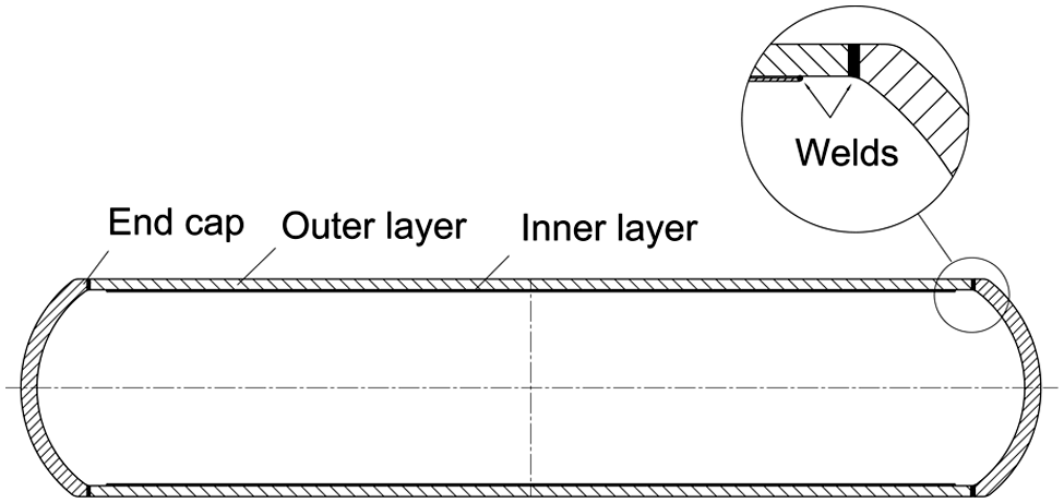
Diagram of double-layered tube specimen.
Mechanical properties of inner and outer tubes.
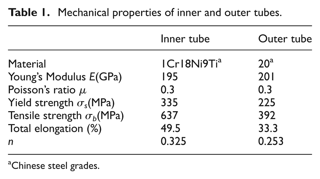
Chinese steel grades
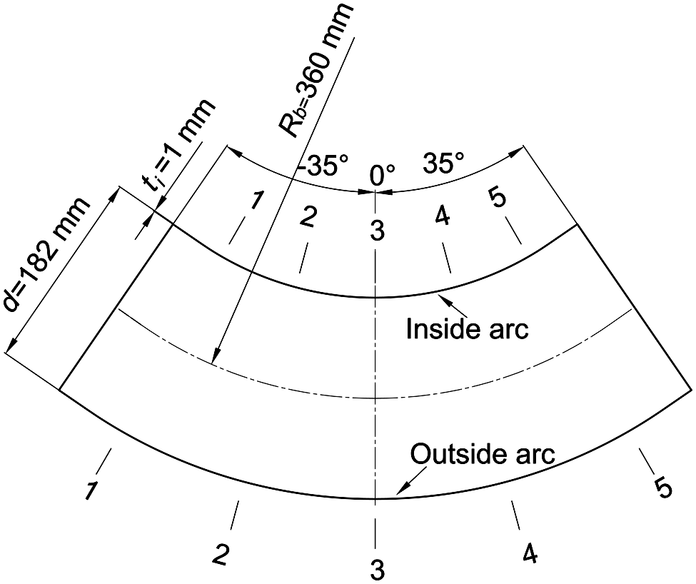
Dimensions of ultra-thin-walled elbow, number 1–1 to 5–5 are the measuring locations of section flattening after bending.
Calculation of yield pressure of a double-layered tube
The pressure value p y , under which the inner wall of the outer tube just satisfies the yield criterion, is referred to as the yield pressure of the double-layered tube. The section view of the double-layered tube under internal pressure is shown in Figure 3, where p is the internal pressure, a is the initial inner radius of the inner layer, b is the outer radius of the outer tube, r m is the inner radius of the outer tube, and δ is the gap size between the inner and outer tube. It is assumed that the inner layer is thin enough that it enters the plastic zone entirely once the inner wall yields, and the ideal elastic–plastic model is assumed for the double-layered tubes.
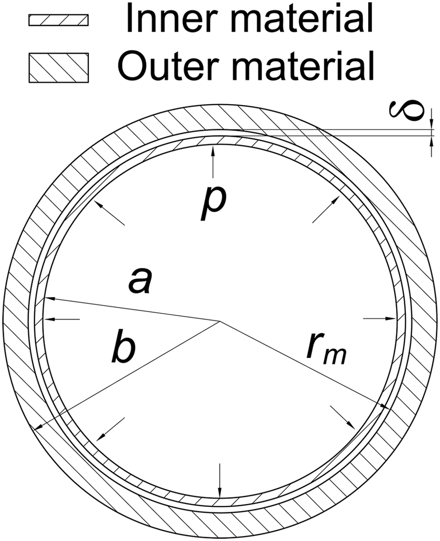
Section view of double-layered tube.
As the inner and outer cylinders are connected at the two ends, as shown in Figure 1, the axial deformation of the inner tube is constrained by the outer one. If the double-layered tube is long enough, it can be assumed that the inner and outer tubes are in a plane strain state when pressurizing, thus we have

where

where
The inner tube enters the plastic zone under pressure p y if the gap size δ is bigger than a critical value. When the non-associated flow rule is employed here for simplicity, 18 in which the von Mises and Tresca yield criteria are employed to describe the yield potential (for the normality rule) and the yield function (for the elasticity boundary), respectively, the von Mises criterion leads to equation (3) so that the axial stress component has no influence on the application of the Tresca yield criterion, especially when the elastic deformation is ignored once the inner tube reaches yielding

where
When δ is bigger than a critical value, the inner tube would enter the plastic zone before it is in contact with the outer tube. The radial stress of the inner tube can be assumed to be zero before the two layers are in contact. Then, based on the plane strain assumption, the principal stresses of the inner tube are derived as
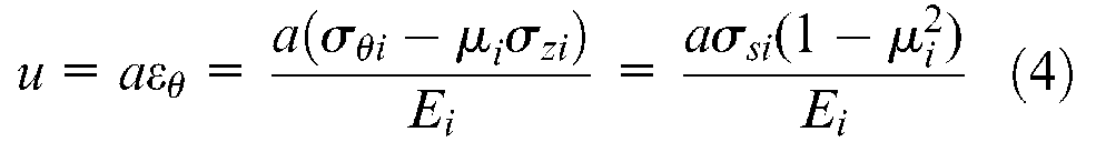
where E
i
represents the Young’s modulus of the inner tube and
Supposing the interfacial radial stress between the two layers is q under the yield pressure of the double-layered tube p y , then the inner layer would be in the plastic regime under the internal pressure p y and the external pressure q, whereby the outer layer would be in an elastic limit state under the internal pressure q. In the plastic zone (inner tube), the following equilibrium equation and the Tresca’s yield criterion are satisfied


The differential equation is solved by substituting equation (6) into equation (5), and by boundary condition


where t
i
is the wall thickness of the inner tube. At the interface we have

In the elastic zone (outer tube), the stress components can be derived from the Lame equation
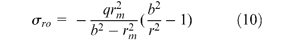
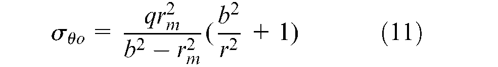
According to the definition of p
y
, at the interface
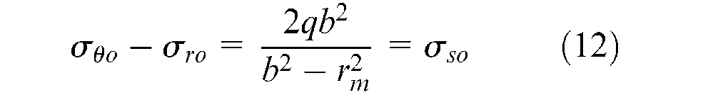
where

Since the radial stresses of the elastic and plastic zones are equal at the interface, equations (9) and (13) lead to
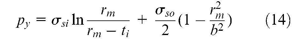
The first term at the right-hand side of equation (14) stands for the plastic limit pressure of the inner layer, while the second term represents the elastic limit pressure of the outer layer.
Based on the above analysis, three principal stresses of the inner and outer cylinders under pressure p y can be expressed as


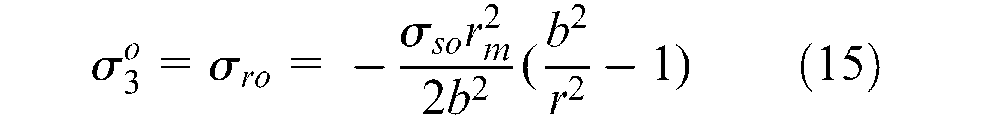
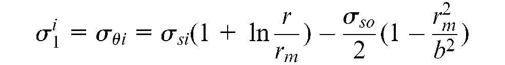
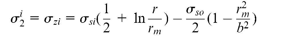
where
Experimental research
Experiment procedure
The experiments were conducted in a hydraulic press. The tooling is shown in Figure 4. The internal pressure was provided by a pressure pump and servo controller to maintain a constant value during the bending process. After the internal pressure was linearly increased to the target pressure, the upper die moved downward to bend the tube into the contour of the die cavity. It can be calculated, according to equation (4), that the critical gap size for the inner layer entering a plastic state is 0.14 mm, which is much smaller than the practical gap size of 0.5 mm. Therefore, the yield pressure of the double-layered tube p y can be calculated as 25 MPa by equation (14). The values of the parameters shown in equations (4) and (14) are as follows: a = 90 mm, σ si = 335 MPa, µ i = 0.3, E i = 195 GPa, r m = 91.5 mm, t i = 1 mm, σ so = 225 MPa and b = 101.5 mm. Four pressure values were chosen in the hydro bending experiments, as shown in Table 2. The slide gage was used to measure the wall thickness of two layers whereby the cross-section dimensions were measured with an outside lock-joint transfer caliper.
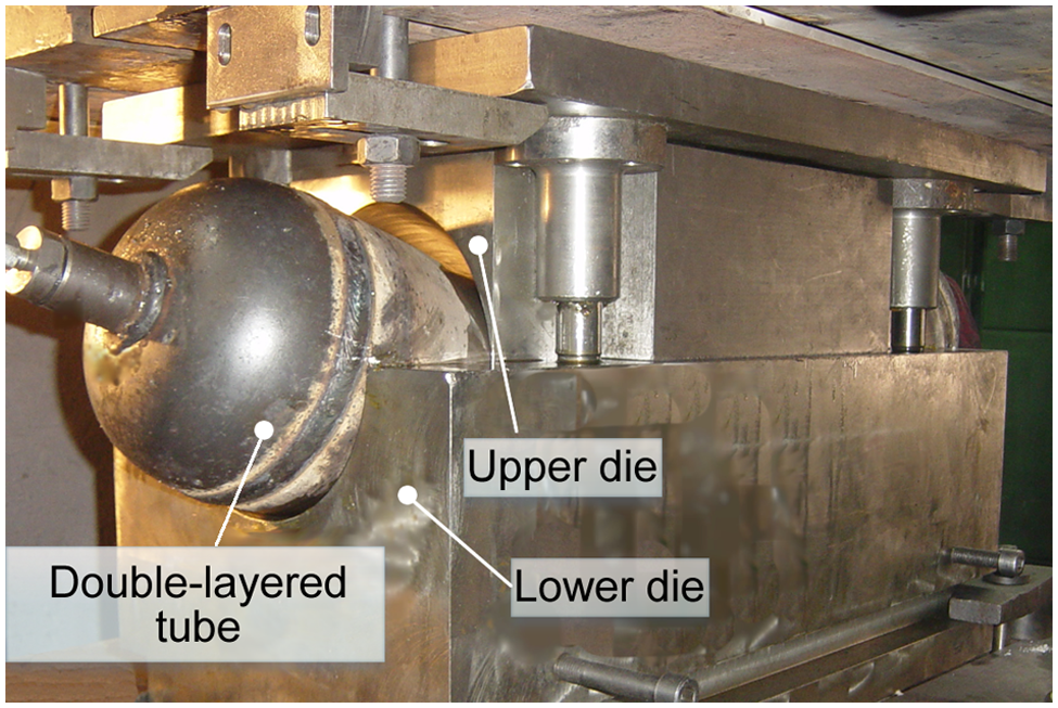
Tooling in double-layered tube hydro bending experiments.
Experimental scheme.
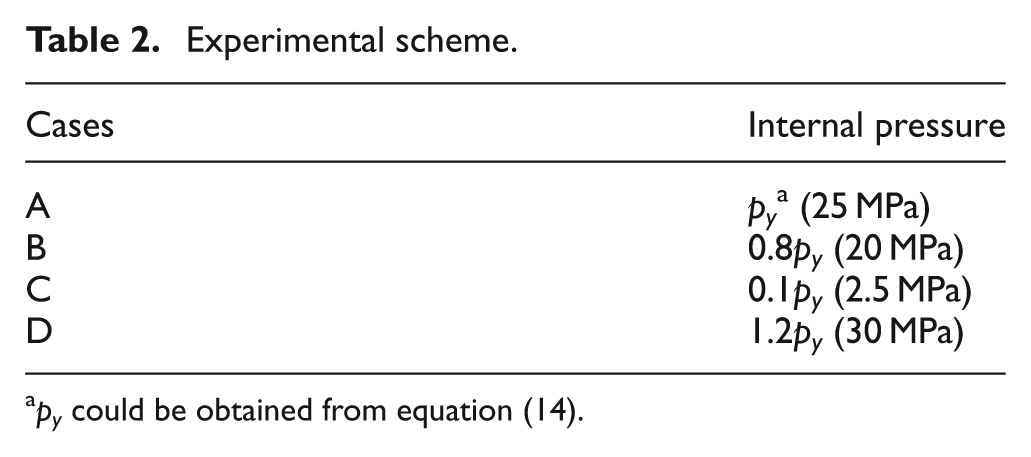
p y could be obtained from equation (14).
Bending results with different levels of internal pressure
Figure 5 shows the experimental results of double-layered hydro-bending with different levels of internal pressure. It can be seen from Figure 5(a) that a wrinkle-free part was obtained under pressure p y . A similar observation was obtained under pressure 0.8p y . In order to observe the forming quality and measure the section distortion and the wall thickness of the inner layer, the double-layered elbow was cut along symmetry planes, as shown in Figure 5(b). There was no tiny wrinkle at the surface of the inner layer. It is also noticed that there was a small gap between the inner and outer tube at the inside arc. The maximum gap size along the bending axis under pressure 0.8p y was around 1 mm, whereas under pressure p y was 0.6 mm. A possible explanation for this is that the dissimilar amount of spring back of the two layers results from the different flow stresses of the two materials. With the same effective strain, the spring back of the inner layer should be larger than that of the outer layer.
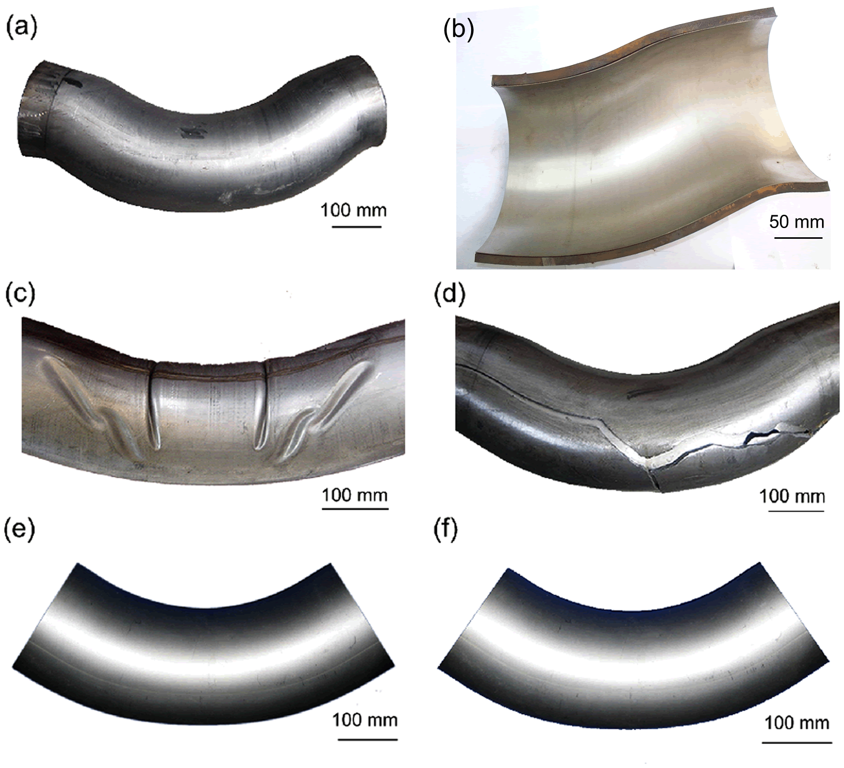
Bending results under different levels of internal pressure: (a) defect-free double-layered elbow formed under p y ; (b) section view of double-layered elbow under pressure p y ; (c) wrinkling under pressure 0.1p y ; (d) rupture under pressure 1.2p y ; (e) ultra-thin-walled elbow formed under pressure 0.8p y ; and (f) ultra-thin-walled elbow formed under pressure p y .
With the internal pressure of 0.1p
y
(2.5 MPa), severe wrinkles were observed at the inside arc of the inner tube, as shown in Figure 5(c). Although the wrinkling did not occur at the outer tube, a large section distortion was observed at the outer tube under this pressure. When the internal pressure was 1.2p
y
, rupture occurred at the outside arc of both layers, while the relative displacement of the upper die (
After bending, the outer elbow tube was cut along the neutral plane from the outer wall to the inner wall by milling and separated into two halves, which were removed from the inner elbow tube. The ultra-thin-walled elbows formed under pressures of 0.8p y and p y are shown in Figure 5(e) and (f). The bending radii of the inside arc (see Figure 2) of the inner elbow tube under pressure 0.8p y and p y are 265 mm and 270 mm, respectively, which were measured with arc templates. The results both meet the design value (268.5 ± 4 mm).
Section deformation
It is shown by the experiments that the section flattening of a double-layered tube under pressure 0.8p y (20 MPa) and p y (25 MPa) are greatly reduced compared with the results under the pressure of 0.1p y (2.5 MPa). A non-dimensional parameter, the non-circularity is used to describe the section flattening of the inner and outer tube after unloading, which is expressed as

where D0 is the initial diameter of the circular cross-section of the tube, while D1 and D2 are the two principal diameters of the elliptical cross-section after bending.
Figure 6 illustrates the non-circularity distribution along the axial direction of the inner and outer layers under pressure 0.8p y and p y . It is indicated that the maximum non-circularity values of two layers are both located at the 3-3 section (see Figure 2), namely the symmetrical section. The non-circularities of the inner layer are larger than that of the outer layer. The maximum non-circularities of the inner and outer layers under pressure 0.8p y are 4.4% and 2.9%, and the values for pressure p y are only 3.3% and 2.5%, respectively.
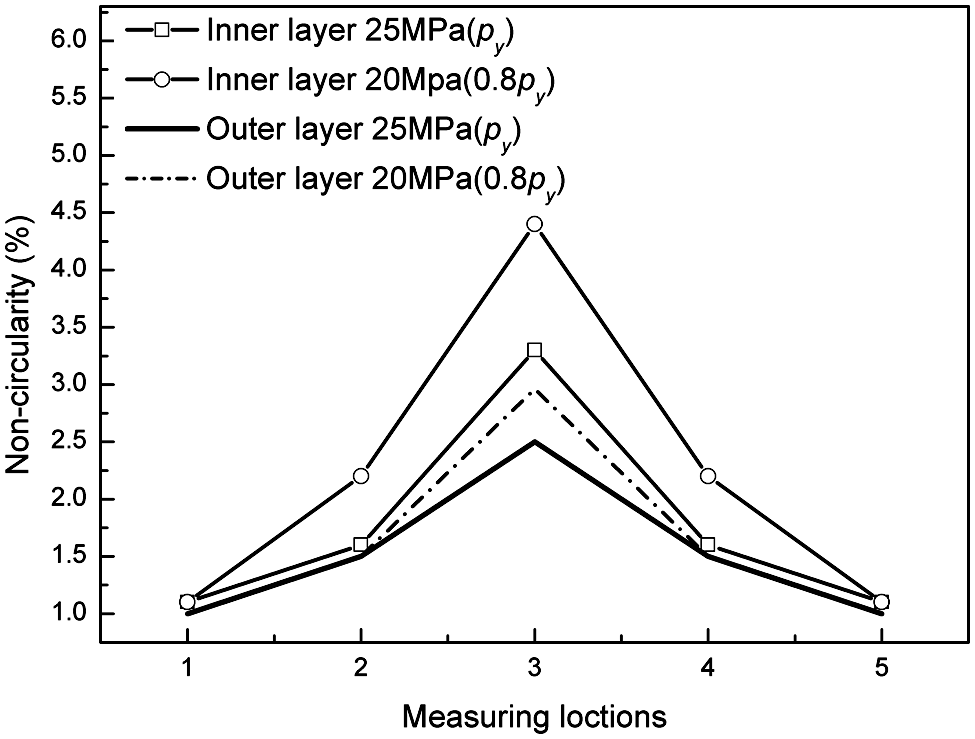
Non-circularities of the inner and outer layers under 0.8p y and p y .
Wall thickness distribution of the inner and outer layer
Figure 7 shows the wall thickness distribution of the inner layer under pressure 0.8p y and p y . It is shown that the wall thickness distributions along the bending axis are generally identical under these two pressure values. The maximum thinning points are located at a 23° angle from the symmetry plane (measuring point 8 in Figure 7), whereby the maximum thickening points are located at the symmetry plane. The wall thickness distribution under pressure p y lies underneath that of pressure 0.8p y . The maximum thinning ratios under pressure 0.8p y and p y are 12.6% and 14%. The maximum thickening ratios are 12.9% and 11.3%, respectively.
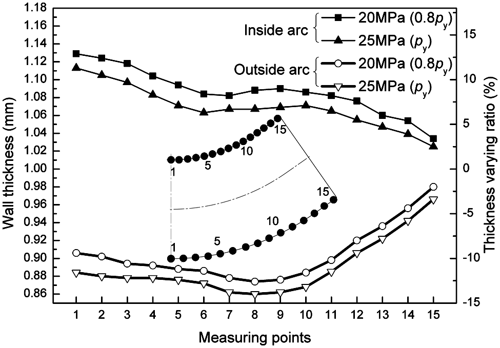
Effect of internal pressure on the wall thickness distribution of the inner layer.
The thinning ratios of the inner and outer layers under pressure p y are shown in Figure 8. It can be seen that the thinning ratio of the two layers are very similar along the inside and outside arcs. The maximum thinning ratio of the outer layer is 13.9%, which is 0.1% smaller than that of the inner layer. The maximum thinning point of the outer layer is located at a 21° angle from the symmetry plane (measuring point 7 in Figure 8). The maximum thickening ratio is 11.3%, which is the same as that of the inner layer. The maximum thickening point of the outer layer is also located at the symmetry plane. It could be deduced from the thickness distribution that the two layers deform conformably during the bending process.
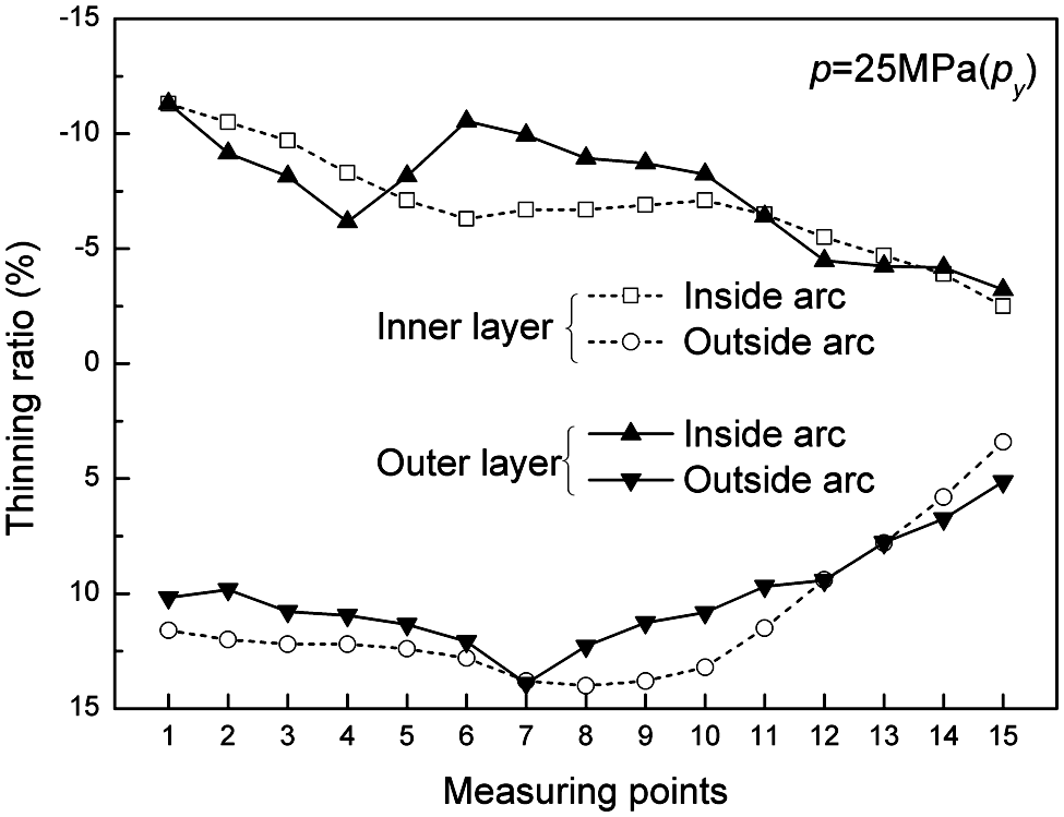
Comparison of thickness distribution trends of inner and outer layers.
Mechanism of wrinkling and stabilizing of the inner tube
The increasing axial stress at the compression side during bending causes the bifurcation instability (wrinkling) of the thin-walled tube, when the compressive stress exceeds the critical value. 19 The internal pressure plays an important role in the successful forming of the double-layered elbow. On one hand, the higher the internal pressure, the more a “tight fit” bond would be formed during bending. The bond between the two layers would increase the critical wrinkling stress of the inner layer greatly. On the other hand, a larger additional axial tensile stress could be introduced to the inner layer if a higher internal pressure is applied. The additional axial tensile stress would decrease the magnitude of the axial stress at the compression side. This section focuses on the wrinkling behavior and the effect of internal pressure on the axial compressive stress at the inside arc.
Finite element model
The finite element analysis code ABAQUS/Explicit was employed to study the wrinkling mechanism under lower pressure values. Only half of the numerical model in the view of geometry and loading symmetries was built up, as shown in Figure 9. The upper die and lower die were assumed rigid, while the inner tube was modeled using S4R (four-node quadrilateral shell with reduced integration) elements, with the mesh size of 6 mm and with five integration points along the thickness direction. The outer tube was separately modeled with shell (S4R) and solid elements (C3D8R, eight-node three-dimensional (3D) brick element) for comparison purposes, as shown in Figure 9. For the lateral case, four layer brick elements are created along the thickness direction, and the element dimension is around 2.5 mm × 5 mm ×5 mm. The material model used for two layers was isotropic, homogeneous and elastic–plastic material following the Mises yield criterion. The ends of the two layers were tied together to simulate the tensile forces of the outer layer applied to the inner layer. The materials properties around the weld line are assumed to be the same as the base material of the outer tube. The Coulomb friction model, with a coefficient of 0.1, was used for all contact surfaces. A constant pressure was applied to the inner surface of the inner tube and the end caps. Based on the experiment results, the internal pressure values including 0 MPa, 2.5 MPa (0.1p y ), 5 MPa (0.2p y ) and 20 MPa (0.8p y ) are adopted in the simulation.
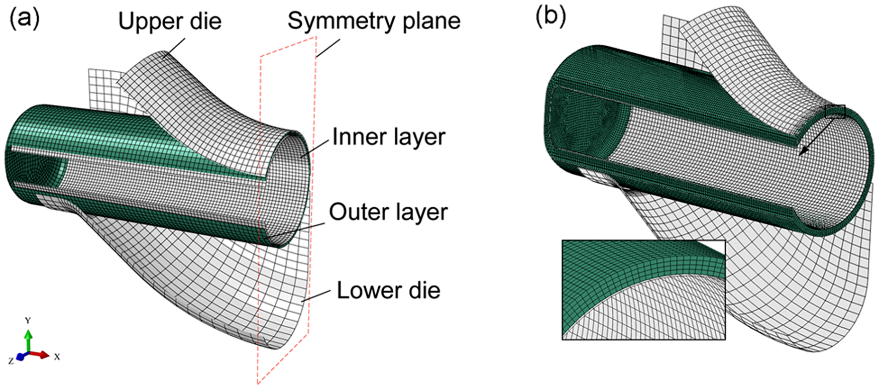
Finite element meshes for double-layered tube hydro bending: (a) shell type outer tube and (b) solid type outer tube.
Wrinkling behavior of inner tube with different pressure values
The wrinkling behavior of the inner tube with different levels of internal pressure is shown in Figure 10. It is shown that the stability of the inner tube is highly associated with the internal pressure, and the wrinkling behavior of numerical predictions with solid- and shell-type outer tubes are generally in fine agreement. The internal pressure could delay the onset of wrinkling. It is seen from Figure 10(a) that the wrinkling was observed in the absence of internal pressure as h reached 10.5%. Similarly, the wrinkling occurs in a same manner under pressure 0.1p y as h′ reaches 15.8%. However, the wrinkling phenomenon was just avoided in the whole bending process under the pressure of 5 MPa (0.2p y ), as shown in Figure 10(c). The inner layer is stabilized under the higher levels of internal pressure (Figure 10(d)). Figure 11 compares the measured and numerical predictions of wall thickness distribution of the inner elbow tube, where the numerical results of two types of outer tube are presented. It is shown that both the numerical simulations predicted generally agreeable results in comparison with the experimental result. At the inside arc, the maximum differences between the experimental and numerical results are 3% (solid type outer tube) and 2.4% (shell type outer tube), while at the outside arc the differences are less than 1.5%. The differences between two numerical predictions with solid and shell types of outer tube are even smaller.
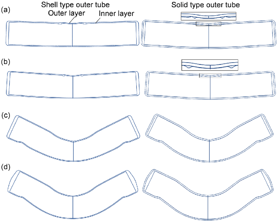
Effect of internal pressure on the wrinkling behavior of the inner layer under (a) pressure 0 MPa as h′ = 10.5%; (b) pressure 0.1p y as h′ = 15.8%; (c) pressure 0.2p y as h′ = 100%; and (d) pressure 0.8p y as h′ = 100%.
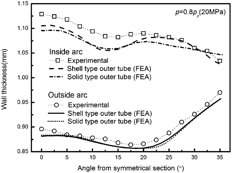
Comparison of experimental and numerical predictions of wall thickness distribution of the inner elbow tube.
From the stabilizing mechanism mentioned above, it is shown that a higher internal pressure should be adopted to obtain a “tight fit” bond and a larger axial tensile stress. It is also shown from the experiments that a higher level of internal pressure is the promise of lower section flattening and higher bending quality. However, the increase of internal pressure should not exceed the yield pressure of the double-layered tube, as shown in equation (14), otherwise the outer tube will be plastic expanded and have a negative effect on the bending precision and formability (for example bursting).
Effect of internal pressure on axial compressive stress at the inside arc
It is believed that the axial stress of the inner tube has a significant effect on the wrinkling behavior at the inner arc. Figure 12 shows the axial stress distribution on the outer surface of the inner tube when h′ is 25%, which is predicted by the numerical model with a solid-type outer tube. It is seen that severe wrinkles take place at the inner arc without internal pressure. The position with the maximum magnitude of compressive axial stress is located at the wave trough of the wrinkles, where the axial stress magnitude reaches −646.6 MPa. Similarly, wrinkles occur at the inside arc under the pressure of 2.5 MPa (0.1p y ), and the maximum compressive axial stress decreases to −627.6 MPa. With the internal pressure of 0.2p y and 0.8p y , no wrinkling occurs at this moment, and the distances from the symmetry plane to the points with maximum magnitudes of axial stress are 23 mm and 47 mm, respectively. The maximum compressive axial stress decreases to −545.4 MPa and −534.1 MPa under pressure 0.2p y and 0.8p y , respectively. The principal stress states of the maximum axial compression points are also shown in Figure 12. It is shown that at these points, the major plane principal stress is along the hoop direction, and the minor one is along the axial direction. It could be concluded that the maximum magnitude of compressive axial stress at the inner arc decreases as the internal pressure increases, which would delay the onset of the instability, and even prevent the wrinkling during the hydro-bending process.
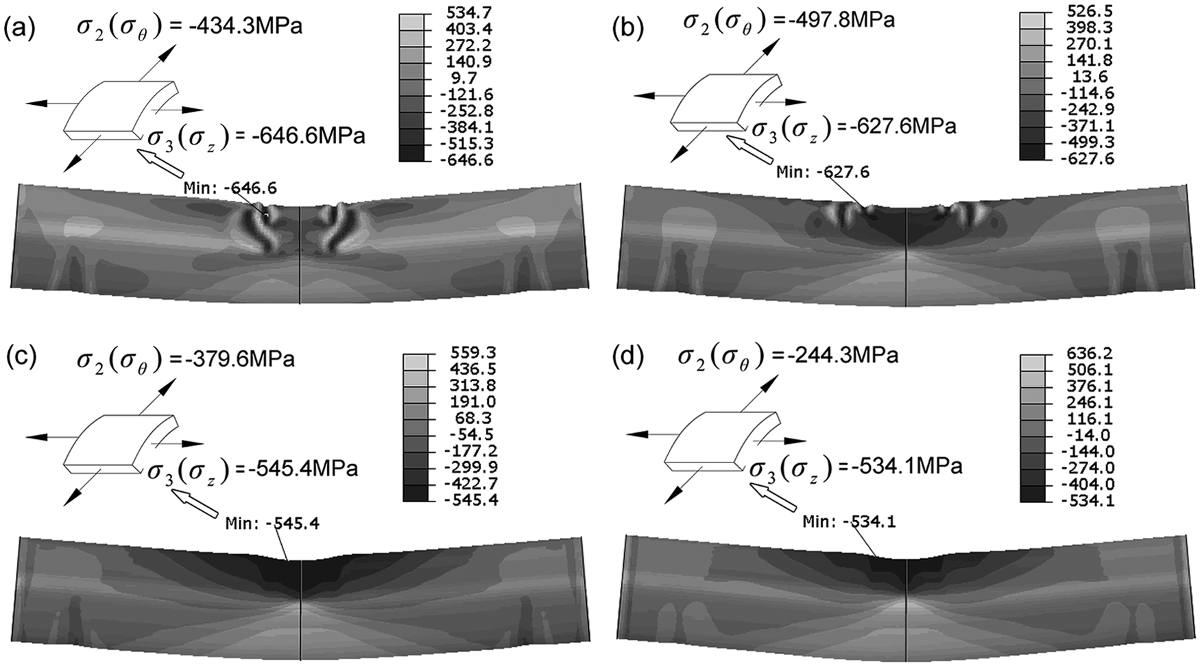
Axial stress (MPa) distribution of the inner layer with different pressure values: (a) 0 MPa; (b) 0.1py (2.5 MPa); (c) 0.2py (5 MPa); and (d) 0.8py (20 MPa).
Conclusions
The fundamental bending behavior of the double-layered tube in the presence of internal pressure is analyzed by both experimental and numerical simulations. The effects of internal pressure on the section flattening, the wall thickness distribution and the wrinkling of the inner layer are analyzed. The following conclusions can be obtained.
The section stiffness of the double-layered tube can be enhanced greatly with the internal pressure increases. The maximum non-circularities of the inner and outer layers under 0.8 times the yield pressure are 4.4% and 2.9%, and the values under the yield pressure are only 3.3% and 2.5%, respectively.
The thickness distributions of two layers are very similar, with the maximum thinning points located at an angle from the symmetrical section. The wall thicknesses of the two layers decrease as the internal pressure increases.
The internal pressure delays the onset of wrinkling and enhances the stability of the inner layer. It is shown from the simulation that the maximum magnitude of compressive axial stress at the inner arc decreases as the internal pressure increases. The inner tube is stabilized when the maximum magnitude of compressive axial stress is less than the critical buckling stress of the inner layer throughout the bending process. This is the reason for the prevention of the wrinkling under higher levels of internal pressure.
Footnotes
Funding
This work was supported by the National Natural Science Foundation of China [grant numbers 51175111, 50875060].