
Abstract
The bonding strength, and microstructures of Cu and Al couples using metallic powders as interlayer during transient liquid phase bonding (TLP bonding) were investigated. The interfacial morphologies and microstructures were studied by scanning electron microscopy equipped with energy dispersive X-ray spectroscopy, and X-ray diffraction. First, to explore the optimum bonding time and temperature, nine samples were bonded without interlayers in a vacuum condition. Mechanical test results indicated that bonding at 560°C in 20 min returns the highest bond strength (84% of Al). This bonding condition was used to join ten samples with powder interlayers. Powders were prepared by mixing different combinations of Cu, Al (+Fe nanoparticles) and Zn. In the bonding zone, different Cu9Al4, CuAl, and CuAl2 intermetallic co-precipitate. The strongest bonding is formed in the sample with the 70Al (+Fe)-30Cu powder interlayer. Powder interlayers present thinner and more uniform intermetallic layers at the joint interface.
Keywords
Introduction
Copper and aluminum metals are widely used in various industries due to their high electrical and thermal conductivity.1,2 The existence of different physical properties, such as density of these two metals, has made the use of copper-aluminum bimetal parts necessary in many cases. 3 Cu/Al bimetals are widely employed in the power industry. For instance, Cu/Al bimetal cables are used in connecting transitions in high direct-current bus systems. There are various technique for joining the Al to Cu such as friction stir welding and explosion welding.4,5 According to novel advantages of Cu and Al bonding based on transient liquid phase bonding (TLP), this technique was considered in this study. Finding the optimum joining condition were considered as the main goal in this research. TLP bonding was first proposed by Paulonis et al. 6 in 1971 to improve diffusion bonding in Nickel Alloys. This bonding process is based on isothermal solidification and solid-state diffusion. Shirzadi and Saindrenan 7 in 2003 declared possibility of jointing dissimilar materials with minimal detrimental effects at the bonding interface are among the advantages of this bonding process.
In previous reports on TLP bonding of Al to Cu, process time, temperature, pressure, and interlayer composition were considered as critical parameters on the bonding quality. In Table 1, TLP bonding parameters experimented by other researchers for joining Al and Cu to other metals and to each other are presented.
Summary of TLP bonding parameters for Al and Cu.
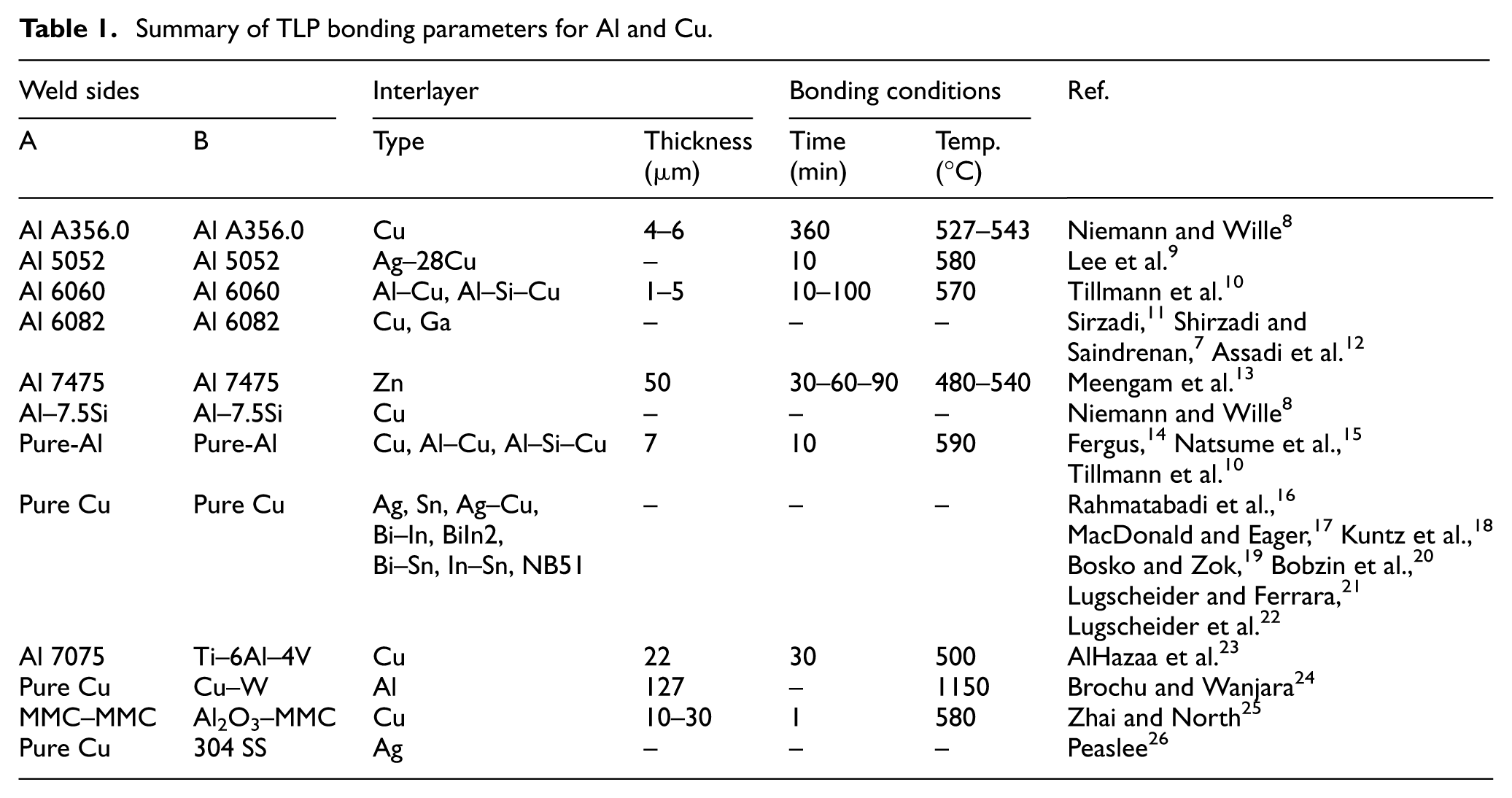
Dray 27 used 1-μm Cu interlayers for the TLP diffusion bonding of Al-6061 and obtained tensile and impact strengths that were close to the strength of the parent material. The samples were bonded at 555°C for 10 min, followed by 30 min at 450°C. The presence of a dendritic pattern at the interface was known as a clear evidence of melting. TEM and EPMA investigations revealed Cu-rich precipitation in the matrix away from the bond line and also segregation of magnesium and silicon, as Mg2Si particles, at the interface. Han et al. 28 in 2015, have investigated the influence of metallic particles as interlayers on microstructure and mechanical properties of Al/Cu diffusion bonding. Their experiments were carried in a vacuum and Ar atmosphere to protect the bonding from oxidation. They have reported that the reaction between Al and Cu at the 550°C causes formation of CuAl2, Cu9Al4, and CuAl intermetallic compounds at the joint interface. These intermetallics also reported by Zare et al. 29 in the interface zone of Cu and Al in compound casting. To join Ni Base Super alloy, Lee et al. 30 have used a mixed Powder of base metal (GTD-111) and base filler (GNi-3). This bond was performed at 1190°C at different times. In the case of a lower 50 wt%, the base metal powders completely melted, and also in the case 60 wt% and higher, the base metal powders partially melted and remained in the vicinity of the bonded interlayer. Roy et al. 31 studied bonding of a 6061Al-15 wt.% SiC extruded composite using a 50-µm thick mixed Cu-Ag powder interlayer. In their experiments, 2 h were necessary for completion of isothermal solidification. The subsequent cooling formed a ternary phase mixture (α-Al + CuAl2 + Ag2Al) upon eutectic solidification. They concluded that using metallic powder as interlayer reduced the isothermal solidification time compared to Cu foil as an interlayer. Application of powder mixtures that contains base-alloys as interlayer material is investigated by Afolabi and Ojo 32 for wide-gap brazing. They have reported that this type of interlayer can be used without partial melting of the additive powder particles, which is crucial to the properties of brazed single-crystal and polycrystalline alloys. Salmaliyan and Shamanian 33 investigated the effect of Ti powders on mechanical and metallurgical properties of IN718/BNi-2/316L diffusion couple. Their researches showed that the existence of eutectic phase, dendritic solidification and joint hardness increases by Ti addition.
In this study, finding the optimum bonding condition using the Aluminum and Copper powder was studied. As the Aluminum and Copper are the two sides of the joint, their powders were used to increase their miscibility and form a more homogeneous microstructure at the interface at lower temperatures and shorter times. The obtained results may lead to lower welding induced residual stresses and consequently higher strength and fatigue resistance.34,35 In the present study, to reach the optimum bonding conditions (time and temperature), bonding of Cu/Al couple without interlayer was investigated in vacuum atmosphere. Next, applying the optimum time-temperature conditions, several metallic powder mixtures were applied to the bonding interface. Different combinations of Cu, Zn, and Al (+Fe nanoparticles) powders were used as interlayers. The existence of the Fe particles in the interlayer composition is due to the investigation of new phase compounds (at the interface) and its effect on the mechanical properties of the bonding zone. 36 Bonded samples are carefully studied to identify the formed intermetallics at their interfaces and to quantify the bond mechanical properties. The best combination of powders for using as TLP bonding interlayer was proposed based on mechanical properties and interface microstructure.
Specimen preparation and experimental study
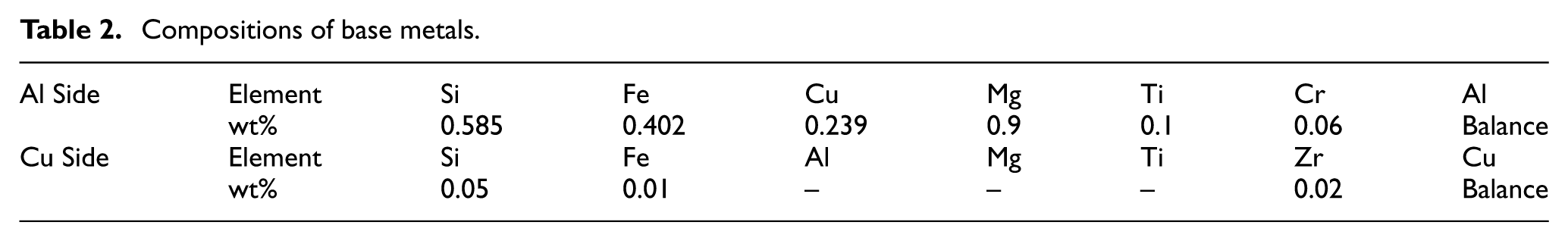
Cylindrical specimens were machined with a diameter and height of 10 mm from both commercial purity copper and Al 6061 alloy. 37 Mass spectrometry results of chemical analysis of the two sides of the joint (Al and Cu cylinders) are presented in Table 2.
Compositions of base metals.
As previously introduced, in this study, Cu and Al are bonded in two conditions; with and without interlayers. In the first set of experiments, nine samples with different bonding times and temperatures are prepared (Figure 1(a)). This group of samples is labeled by P1 to P9 according to Figure 1(a).
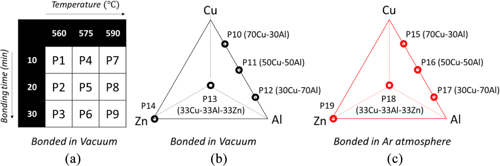
(a) Experimental conditions for achieving the best processing conditions. (b and c) Selected interlayer compositions and relative sample codes for bonding at 560°C and 20 min in a vacuum and Ar atmosphere, respectively.
For experimental design, first, the allowable range of parameters was determined from the literature. Base on the primary study, the temperatures must be above the eutectic point and bellow the melting point. Han et al. 28 showed that all the selected temperatures were above the eutectic (TE = 548.2°C) to form isothermal solidification. Upon isothermal solidification the liquid phase is solidified at the bonding temperature. 38 So the three temperature levels were selected. Times were selected based on literature review, trials and microstructure observations to see if isothermal solidification is formed, not formed or partially formed. Consequently, the minimum and maximum admissible time were selected and the three levels for bonding time were defined. The full factor experimental design technique has been used at this step.39,40 For the second set of experiments, assemblies were designated as P10−P19 according to Figure 1(b) and (c). These specimens were bonded in vacuum (P10−P14, Figure 1(b)) and argon atmosphere (P15−P19, Figure 1(c)) with the different weight proportions of Cu, Al, and Zn powder. All bonding temperature and time used for the second set of samples were selected based on the best strength results of the first set of samples which was set at 560°C for 20 min.
In Figure 2(a)–(f), the scanning electron images of the metal powders are shown. While the Al and Zn particles are spherical, the Cu particles have dendritic shapes. As indicated in Figure 2(b), the Al powder is premixed with Fe nanoparticles (∼100 nm). These particles are later shown to have important effects on phase transformations at the interface.
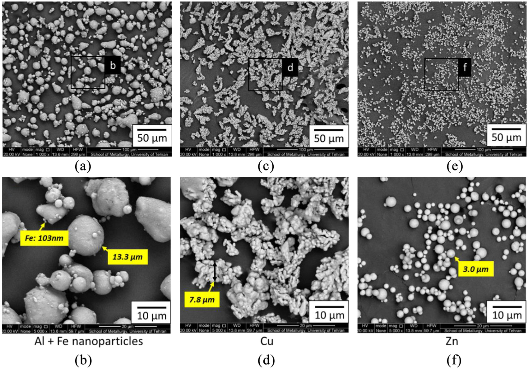
Back Scatter Electrons (BSE) micrographs of the metallic powders used as interlayers for the TLP process (a, b) Al, (b, c) Cu, (e, f) Zn.
According to the functional mechanism of the fixture (shown in Figure 3), which requires the placement of completely flat pieces, in both sets of experiments, the bonding surface of samples was ground by 600 grit sandpaper. The stacked samples are placed in a specially designed, environmentally controlled induction furnace (Figure 3). In all the joined samples, Al side was positioned at the top the Cu side. Samples are processed in both Ar and vacuum to avoid the formation of oxides that prevent formation of metallurgical bonds. 16 An induction coil with a heating rate of 200°C/min was used to control the temperature. The pressure was applied by the three steel springs shown in Figure 3 (Under Hooke’s law, the pressure applied to the samples was measured about 0.2 MPa). After ending of every test Samples cooled down slowly inside the furnace. The temperature is measured with a K-type thermocouple positioned into a hole in the copper rod close to the interface. After completing the bonding process, samples were investigated with shear test, and microhardness test which is carried out with a load of 100 g. To reveal the microstructures of bonded interface, sections were made perpendicular to the circular cross-section and were carefully ground by sandpapers and polished by 1-μm alumina suspension to observe microstructures with scanning electron microscope (SEM) device. 41
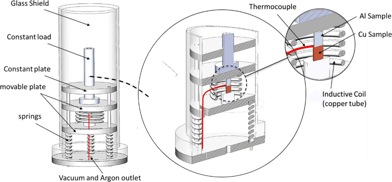
The atmosphere control TLP bonding setup.
Results and discussions
Thermodynamic simulations
To investigate the effect of Mg alloying addition on the bonding process of 6061 alloy, Al-Cu and Al-Cu-0.5Mg phase diagrams were simulated by Thermo-Calc (as shown in Figures 4 and 5 respectively), at the eutectic reaction on the Al rich side, primary Al (α-Al) and CuAl2 (θ) phase are formed by solidification of the liquid phase. Based on the phase diagrams, at the temperature range between 550°C and 590°C, it is expected that α and θ are the main phases at the bonding region after isothermal solidification (horizontal movement on the dashed lines).
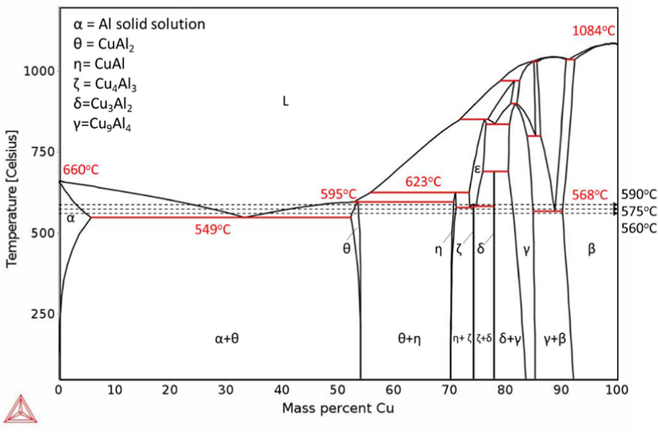
Calculated Al–Cu binary phase diagram indicating transformation temperatures and intermetallic phases.
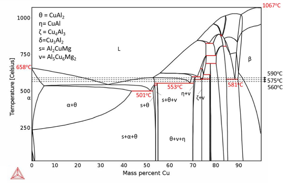
Calculated Al–Cu–0.5Mg pseudo binary phase diagram indicating transformation temperatures and intermetallic phases.
By comparing the phase diagram of Figures 4 and 5 it can be concluded that the presence of 0.5% Mg will not change the eutectic point significantly. However, the diagram shows the presence of an s phase (Al2CuMg) among solidification products.
Mechanical properties of samples bonded without interlayers
To evaluate the mechanical strength of bonded samples, the joined surfaces were tested by a shear test fixture. Figure 6 shows the fixture that secures the samples in a universal testing machine assembly (SANTAM STM-20). 42 Each half of the bonded sample sits inside the drilled hole of separate sides of the hardened steel fixture. The shear stress–shear strain curves were plotted and reported for all the examined samples.
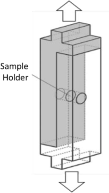
The shear test fixture, showing the sample holder cavities and the loading direction.
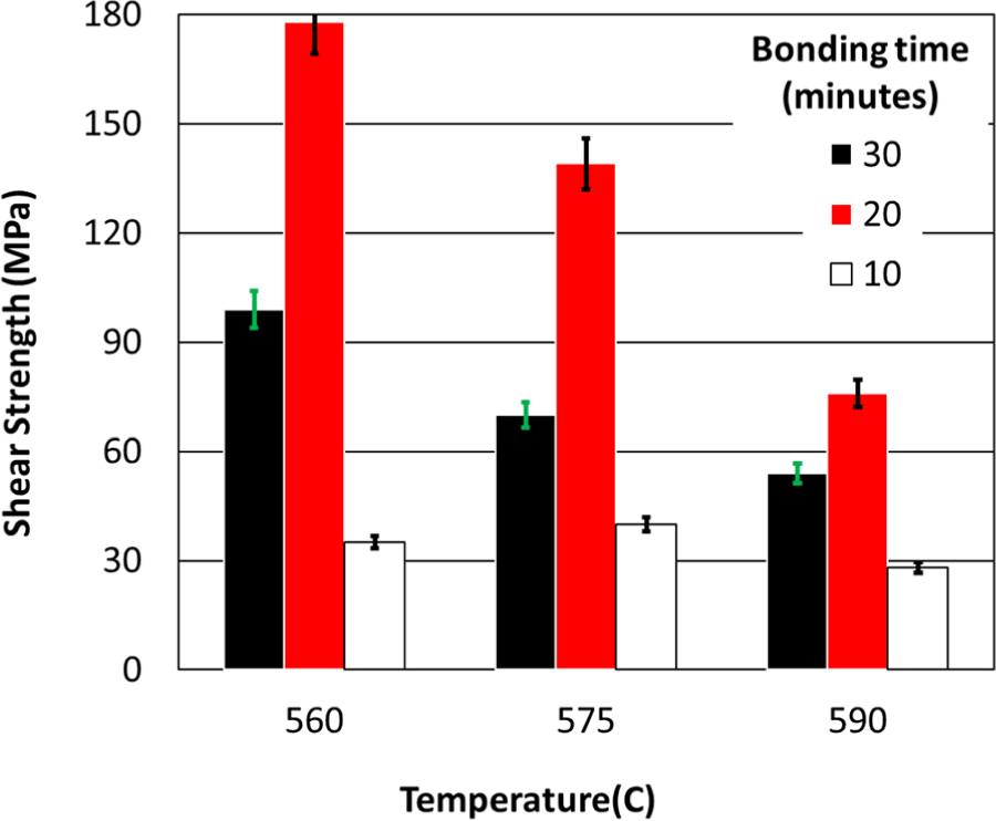
Figure 7 compares the shear strength of samples bonded without interlayers. The strongest sample withstood applied shear stress of 178 MPa (84% of Al shear strength) was bonded at the P2 test condition (t = 20 min, T = 560°C). The minimum strength was recorded for the sample bonded at 590°C and 10 min (P7 test condition). Results show that shear strength decreases by increasing the temperature when samples are bonded for 20 and 30 min. This is attributed to the fact performed by Shirzadi 43 that thicker interlayers form at higher temperatures which reduces the bonding strength.
(a) Shear strength of the TLP bonded samples without interlayers.
Microstructure and fracture surface of samples bonded without interlayers
Regarding the results shown in Figure 7 (the samples bonded without an interlayer), the samples with the minimum (590°C, 10 min) and maximum strength (560°C, 20 min) are chosen for investigating with SEM microscope. The width of the interface is measured by 210 µm for P2 and 260 µm for P7 samples. This means increasing in width decreases the bonding strength. Figure 8(a)–(c) shows interface bonding of the strongest sample. In this region, CuAl2 (gray color) in the background of α-Al dendrite cell (black color) is visible. Near Cu side, intermetallic composition Cu9Al4 was nucleated after CuAl2. Figure 8(d)–(f) shows the diffusion of Cu in Al relatively is not completed, and Cu9Al4 did not originate in the Cu side. Also cracks near the Cu side are also visible, which might be the reason for weak bonding in this sample.
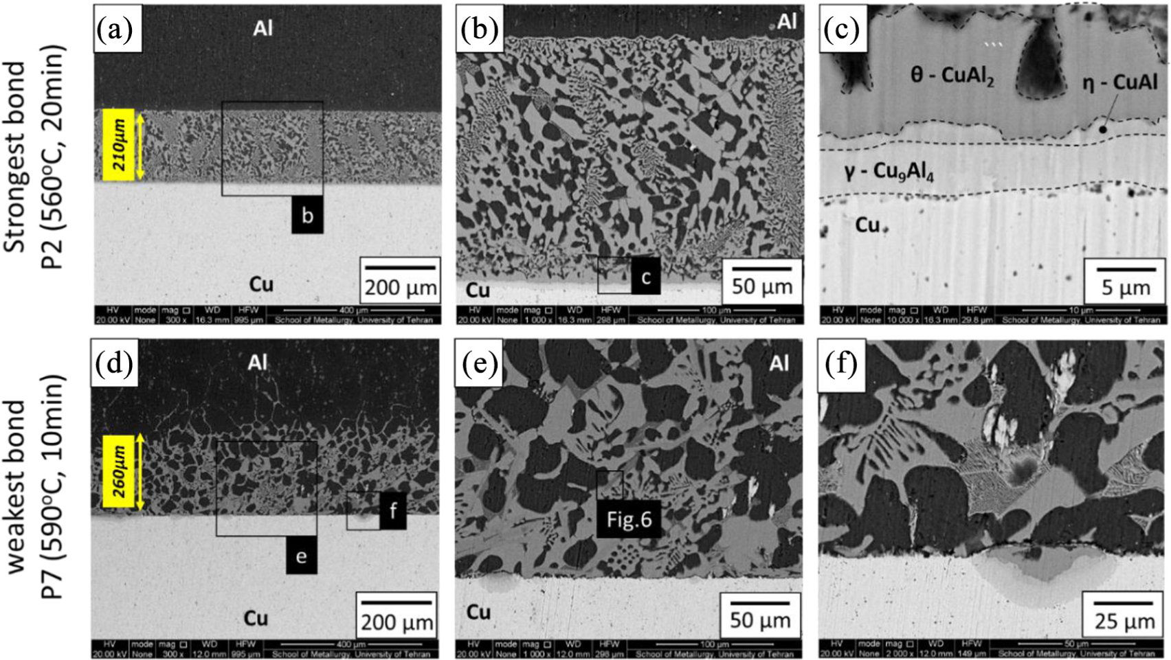
BSE micrographs of the sample bonding zones processed without interlayers at (a–c) P2 and (d–f) P7 test conditions.
In the BSE maps (Figure 8), unknown phases were detected which investigated with SEM to analyze their composition (Figure 9). The analysis proved the exiting of Mg, Cu, and Al on one of the phases. According to the pseudo binary phase diagram illustrated in Figure 4, this phase is Al2CuMg.
SEM analysis of an unknown phase on the interface.
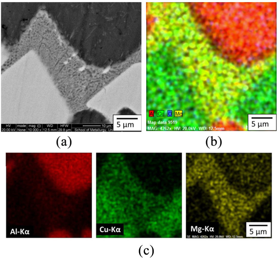
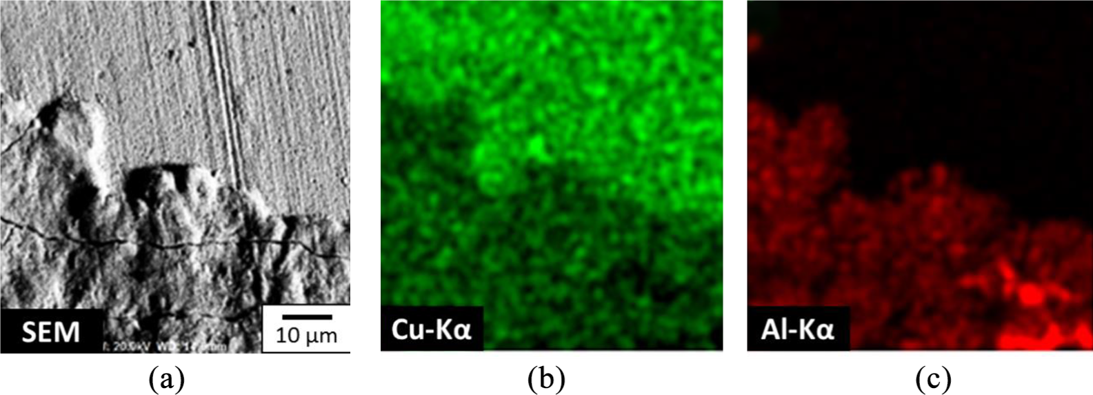
In Figure 10, the fracture surface of the bond processed at the condition resulting in the highest strength (P2) is presented (the Cu-side). The strongly bonded sample shows clear eutectic structures indicating the successful formation of the liquid phase and its complete isothermal solidification. The Energy-dispersive X-ray spectroscopy (EDS) maps of Figure 10 show separation of Cu and Al in the interface intermetallic.
Fracture surfaces on the Cu side after shear test of the samples processed at (a, b) BSE, (c) SEM, and EDS elemental maps of (d) Cu-kα and (e) Al-kα.
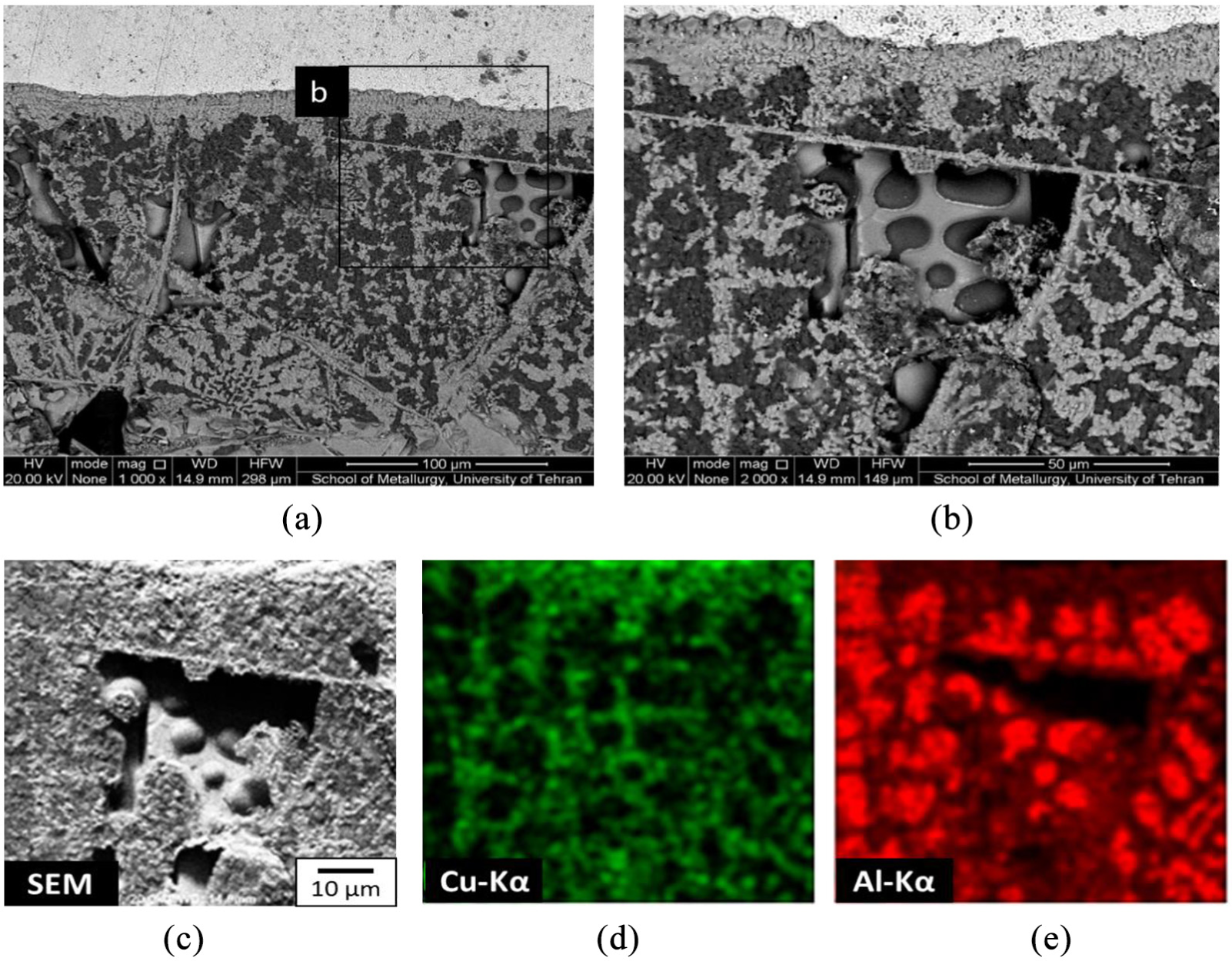
Similar separation is not seen in the weakly bonded sample (Figure 11). In the P7 sample, although an intermetallic interface is formed the bonding time (10 min) was not enough for isothermal solidification and separation of eutectic phases (EDS maps).
SEM and EDS element maps of the fracture surface of P7 test conditions.
The XRD spectrum on the Cu-side of the fracture surface of the strongest bonding condition (P2) is shown in Figure 12. Other than the α-Cu sublayer, peaks of α-Al and CuAl2 are identified in the spectrums. Compared to the results of Figures 8 and 9, the CuAl, Cu9Al4, and Al2CuMg are not detected in the X-ray spectrum due to their very low volume fraction compared to the three main phases (α-Cu, α-Al, and CuAl2).
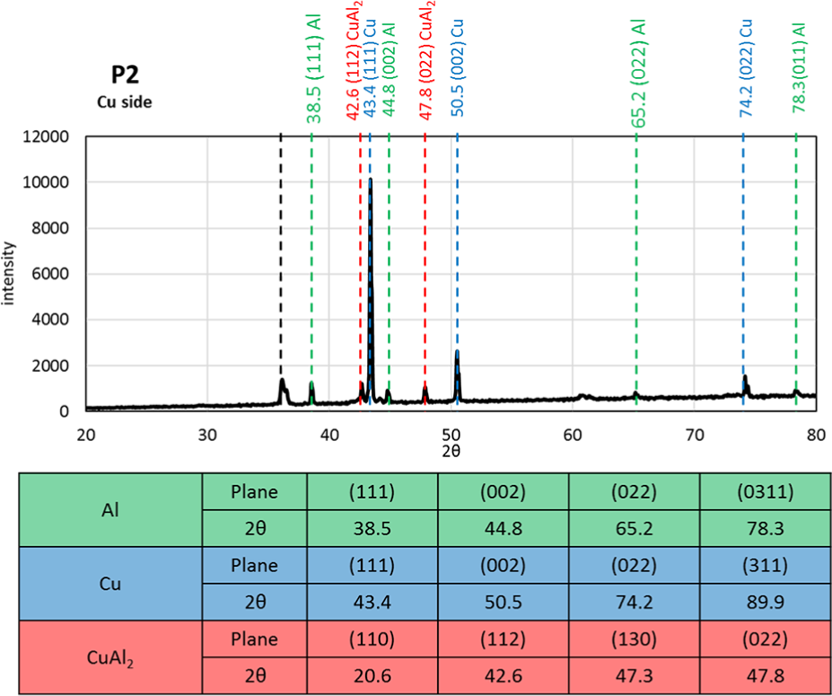
XRD spectrum on the Cu fracture side of the sample processed at P2 test condition.
Mechanical properties of samples bonded with interlayers
In Figure 13, the shear strength of the samples bonded with powder interlayers in vacuum and Ar atmosphere (sample P10−P19) is presented. As previously mentioned, the test condition representing the highest strength was selected for bonding further samples with powder interlayers (P2: 560°C and 20 min). Figure 13 indicates that the highest strength occurs in the P10 bonding condition with a 30Cu-70Al powder composition. In all the studied conditions vacuum atmosphere resulted higher strengths probably by more successful prevention of oxide formation which deteriorates mechanical properties that approved by Shirzadi. 43 Moreover, the results indicate that Zn powder did not provide a high bonding strength either by mixing with Cu and Al (78 MPa) or in its pure format (6 MPa).
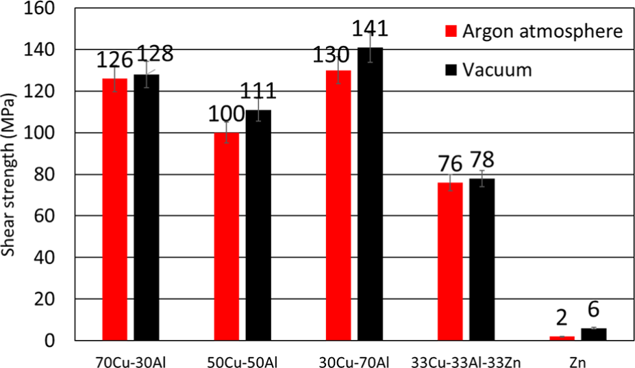
Shear strength of the TLP bonded samples with powder interlayers at 560°C and 20 min.
Microstructure and fracture surface of samples bonded with interlayers
The bonded cross section of the sample presenting the highest strength among the samples processed with interlayers (P10) is presented in Figure 14. The interlayer microstructure was 145 μm and relatively more compact than the samples without the powder interlayer (Figure 8). Compared to the samples without interlayers, when powder interlayer is added the interface becomes more serrated (Figure 8(a) and (b)). Similar intermetallic sequencing is observed at the interface of the interlayer and copper (Figure 8(c)). The EDS element maps of Figure 14 clearly indicate the presence of Fe at the interface. It should be noted that the initial Al powder contained 2% Fe nanoparticles. Later the XRD result will show that Fe has induced formation of a Cu2Al7Fe (ω) intermetallic at the bonding interface.
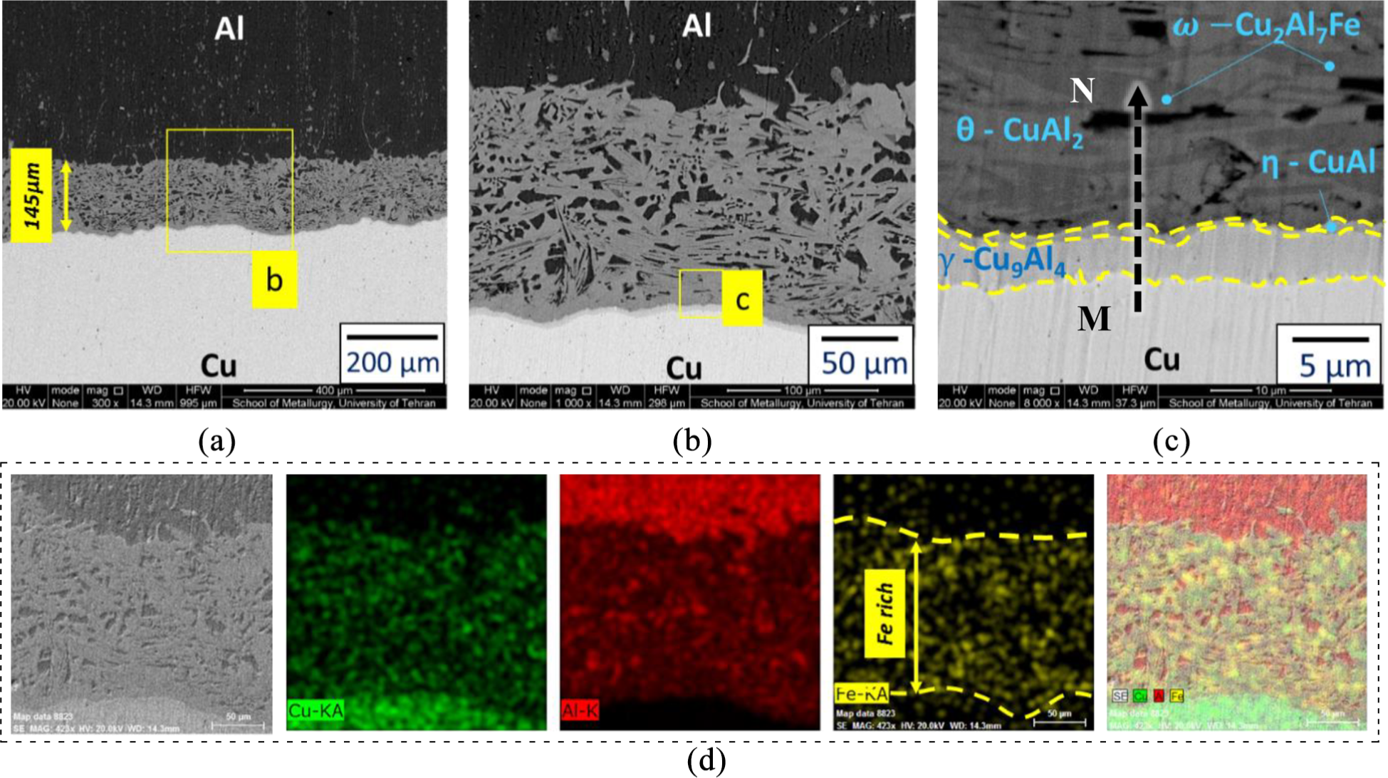
BSE micrographs of the sample bonding zones processed with 30Cu–70Al interlayer processed in the vacuum (P10 test condition).
EDS line analysis of the MN line of Figure 14(c) is presented in Figure 15. The line crosses different phases that can be distinguished by their contrast. The darkest phase represents α-Al which contains some copper as a solid solution. The brightest phase is CuAl2 and the gray phase is the ω-Cu2Al7Fe. Important to mention that the ω phase is not present at the interface of samples processed without powders. The line scan results show high concentrations of Fe where the ω phase is present. The sequence of intermetallic from M (Cu-side) to N (Al-side) is indicated below the diagram of Figure 15. Signs of Fe presence can also be identified in the cross-sections of the sample processed with 70Al–30Cu interlayer.
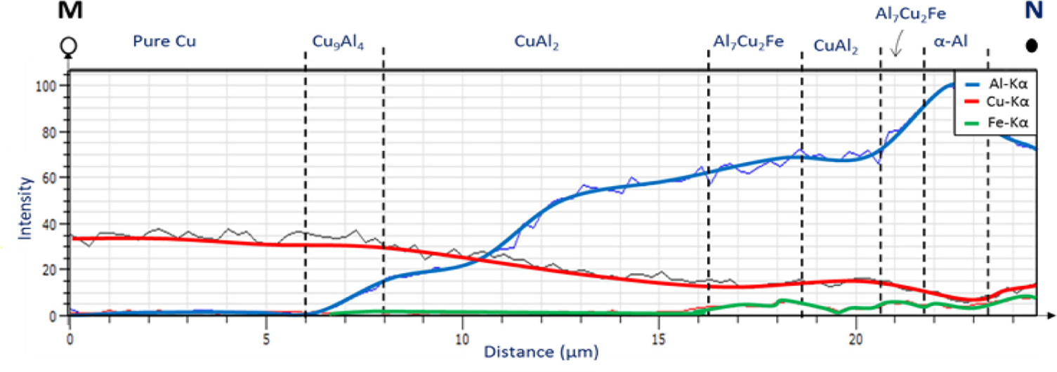
EDS line scans results from point M to N in Figure 11(c).
XRD spectrum of the fracture surfaces of the P10 sample is shown in Figure 16. In both the major intermetallic phases, CuAl2, can be only identified on the Al side and its characteristic peaks are not evident on the Cu side. This is in contrast with what was previously observed for samples without interlayers (XRD and SEM results indicated that CuAl2 was present on both sides).
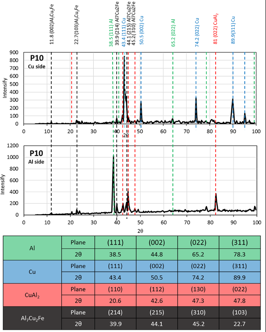
XRD spectrum on the Cu and Al fracture side of the sample processed at P10 test condition.
Micro-hardness testing was based on this observation. It can be concluded that for samples without powder interlayers, fracture propagates through the intermetallic-Cu interface during the shear strength test. In contrast, in the samples bonded with powders and with compact intermetallic layers, fracture propagates through the intermetallic itself. The presence of the ω-Cu2Al7Fe phase in the CuAl2 layer may be the reason for the softer intermetallic interlayer. This has been confirmed with micro-hardness tests which indicate that the intermetallic layer with powder presents 315 HV while without interlayer the intermetallic layer presents a higher hardness of 338 HV. The difference of fracture conditions in the samples bonded with and without powder interlayers is schematically shown in Figure 17. In this figure, sinusoidal shape appears in samples boned with powder interlayer may cause increasing in strength. 11
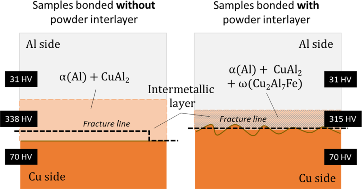
Schematic illustration indicating the difference between the fracture conditions in the samples bonded with and without powder interlayers.
Conclusion
The bonding strength and microstructures of Cu and Al couples using metallic powders as interlayer during transient liquid phase bonding were investigated. The interfacial morphologies and microstructures were studied by scanning electron microscopy equipped with energy dispersive X-ray spectroscopy, and X-ray diffraction. The main obtained results were summarized as below:
Mechanical test results indicated that bonding at 560°C in 20 min returns the highest bond strength (84% of Al).
Interlayer composition of 70Al-30Cu, obtained maximum strength under shear test.
Cu2Al7Fe was a distributed phase appeared across the interface zone of bonding because of 2% Fe nanoparticles. Fe as impurity decreases the bond strength.
Existence of Cu2Al7Fe phase in the bonding region (P10) led to decreasing of hardness measured in the bonding zone versus the sample without interlayer (P2).
Boundary zone in samples using powder as interlayer (P10–P19) are sinusoidal and increase the strength in comparison to flat interfaces that occur in non-interlayer samples (P1–P9).
Footnotes
Declaration of conflicting interests
The author(s) declared no potential conflicts of interest with respect to the research, authorship, and/or publication of this article.
Funding
The author(s) disclosed receipt of the following financial support for the research, authorship, and/or publication of this article: The authors are grateful for the support of the Iran National Science Foundation (INSF), Project No. 98012558.