
Abstract
To fulfill the demands of higher precision, better quality, and more flexibility, the usage of high-performance industrial robots is rapidly increased in aerospace industry. Considering the anisotropic and inhomogeneous characteristics of composite materials, this study focuses mainly on dynamic response investigation of a newly designed hybrid robot (named as TriMule) in CFRP trimming process and its influence on the machined quality. First, combined with the cutting force characteristic, the vibration responses of tool center point (TCP) under the dynamic excitation were obtained. The influences of robotic TCP vibration on machined surface quality with different fiber orientations, including surface waviness, cavity, 3D surface roughness, and depth of affected zone, are first studied by comparing hybrid robot and machine tool. From experiment results, it can be concluded the proposed TCP vibration response model has sufficient prediction accuracy. Meanwhile, it is found that larger robotic vibration response is accompanied by higher surface waviness, bigger surface cavity, and greater affected zone. Results also showed that the fiber orientation and milling style are two essential factors that affect robot vibration and machining quality during CFRP trimming.
Introduction
The application of carbon fiber reinforced polymer (CFRP) in today’s aviation and aerospace industry has been dramatically increased due to its superior properties like lightweight, excellent stiffness, and resistance to corrosion.1–4 Although CFRP materials are usually formed by employing the near-net-shape method, secondary machining processes are often arranged to fulfill dimensional and assembly requirements. For example, the edge trimming process is always required to eliminate the thickness decrease section around the periphery of the pre-preg laminate CFRP. Meanwhile, the resin transfer molding process often has a fiber gap at the periphery to make sure the fibers will not affect the mould seal. In general, the above mentioned peripheral area and loose fibers are always removed by edge trimming as well. 5
For the CFRP parts in the aircraft manufacturing and assembly process, they usually have tremendous size and a wide variety of shapes. To enhance manufacturing productivity, robot-based machining is investigated as an alternative for large-size part on-site manufacturing, and lots of investigations about robot-based CFRP trimming have been carried out recently. However, because of the machining characteristics of CFRP materials, and the low stiffness and poor dynamic performance of industrial serial robot comparing with the CNC machine tool, it is still challenging to realize high surface quality and high dimensional accuracy for CFRP parts robot machining. From the published literature,6,7 it is recognized that both cutting force and TCP vibration have significant impact on the machining quality during the robotic CFRP trimming, such as dimensional accuracy and machined surface quality. Hence, another type of robots named hybrid robots or hybrid kinematic machines, which have larger end-point stiffness, higher positioning accuracy, and higher dynamic response, provides a more economic and desirable way for trimming of large scale CFRP components. 8
Based on Chen et al. 9 and Li et al., 10 it was concluded that the higher machining geometrical accuracy could be obtained by CNC machine comparing with robot-based machining, and the main reason is lower rigidity and poor dynamic behavior for the industrial serial robot. The influence of machine stiffness on geometric accuracy for robot-based CFRP machining has been extensively investigated. Li et al. 10 presented the influence of deformation of TCP during robot helical milling on hole diameter error and found that robot stiffness varies with the position of the machining, and that is the main reason for the diameter error variation in the hole depth direction. Bu et al. 11 also concluded that robot stiffness is directly related to the robot’s posture, and machined hole diameter accuracy can be improved by optimizing the drilling posture. Slamani et al. 12 conducted a series of experiments to compare the corresponding machining quality between robot and CNC machine in CFRP trimming, and the results showed that the evaluation profile obtained by robot are mainly influenced by trajectory deviation. To study dynamic behavior which dominant by robot structure, an ideal elastodynamic model for robot is required first. Dong et al. 13 established a 9-DOF elastodynamic model for Tricept robot based on the screw theory and structural dynamics, and the lower-order dynamic behaviors for the entire robot workspace are estimated based on the proposed model. Wu et al. 14 complete dynamic model of lower mobility parallel robot using substructure synthesis and modal reduction technique. However, the dynamic performance of robot machining system is another important metric for robotic machining capacity, and the influence of dynamic behavior on the machining quality needs to be investigated in detail.
From the literature review, it was found that most studies for robotic machining are focused on the discussion of the machining surface quality caused by regenerative chatter. It was indicated that low frequency mode coupling chatter can generate the vibration in the entire robot, which might lead to unexpected system damages. 15 Meanwhile, in the published literature,16,17 the regenerative and mode coupling chatter were both studied to reveal the mechanism of low-frequency vibration under certain robotic conditions. However, considering the special material removal characteristics of CFRP, the research on dynamic behavior and its influence on CFRP machined quality during robotic trimming need further study.
Based on the elastodynamic model of TriMule hybrid robot, this paper obtained the dynamic response of tool center point (TCP) during robotic CFRP trimming process, and its effect on the machining quality under different fiber angles are also investigated in detail. This paper is structured as follows. The robotic vibration response during CFRP trimming is obtained in Section 2. In Section 3, a series of milling experiments are carried out under both 5-axis NC machining center DMU80T and TriMule hybrid robot to validate the accuracy of proposed prediction model. In Section 4, the results of robotic vibration response during CFRP trimming are discussed and its effect on machined quality is studied by comparing the machined surface quality of hybrid robot and 5-axis NC machining center. The final conclusions are presented in Section 5.
Robot dynamic response analysis during CFRP trimming
As shown in Figure 1(a), a newly designed 5-DOF hybrid robot 18 was applied in this study. It is composed of an overstrained 2-RPS&UPS&RP parallel mechanism with one translation and two rotation degrees of freedom (DOF) and an RR A/C wrist with two rotation DOFs. The parallel part comprises four bases, two base links, a UPS limb, two identical RPS limbs, and a RP limb in which the platform is connected rigidly to the central tube. P, U, R, and S denote prismatic, universal, revolute, and spherical joints separately, and underlined one denotes an actuated joint. For convenience, Figure 1(b) shows the schematic diagram of TriMule hybrid robot. 19
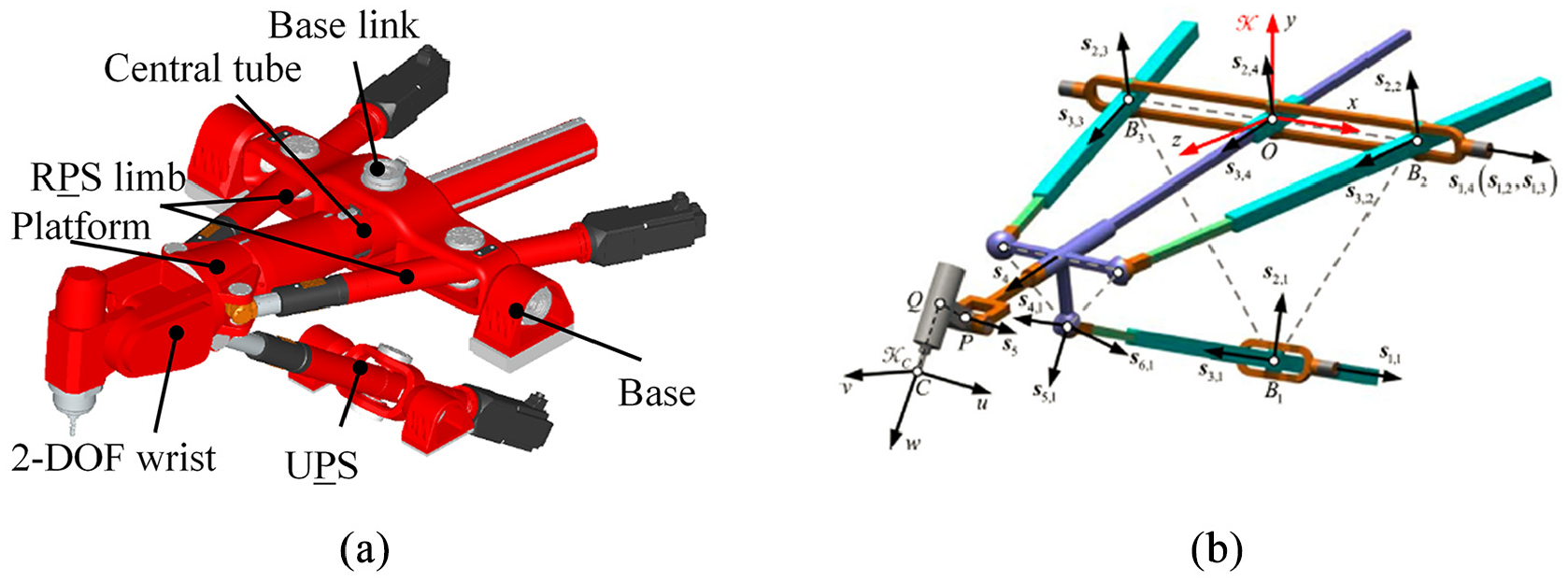
(a) TriMule robot overall structure and (b) schematic diagram.
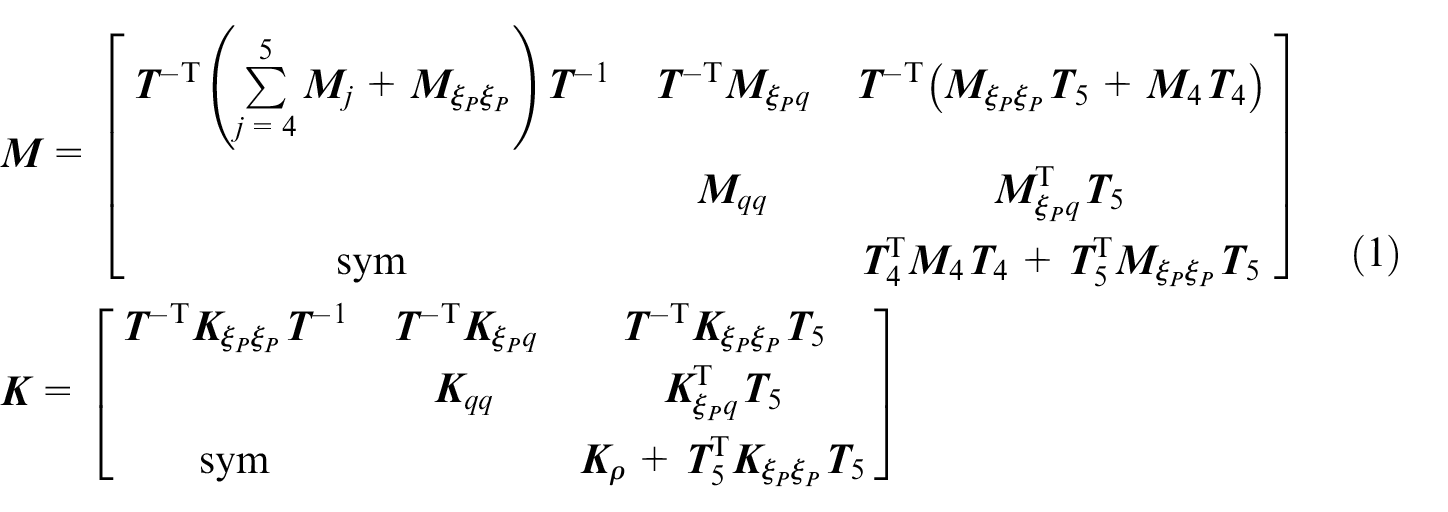
The elastodynamic model needs to be proposed first for obtaining the TCP vibration response during robotic trimming. According to the modeling approach developed by Wu et al.,
19
the elastodynamic model can be obtained by combining elastic potential and kinetic energies for both parallel structure and A/C wrist. Besides, the preference of taking

where
Modal parameters of mechanism like natural frequency, mode shape, and frequency response function (FRFs) can reflect vibration characteristic.20,21 Thus, combined with the modal analysis theory, the characteristic equation of equation (1) can be formulated to study the vibration response, as

The ith natural frequencies fi and frequency response function matrix
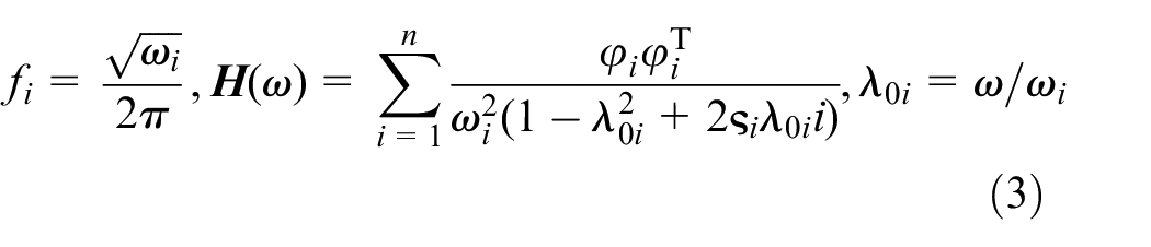
where the modal mass normalization is chosen and ωi,
According to Guo et al.,
22
the mechanism of vibration of robotic machining is the forced vibration, thus let the
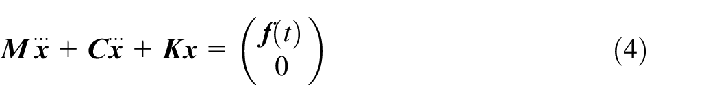
let F and Fa denote the resultant force and axial force during robotic trimming. Projecting the cutting force into x and y directions (X-Z plane) using the exciting cutting angle which expressed in the form of multiplication of exciting frequency ω and time. The solution to the equation (4) leads to the vibration displacement response under three-direction cutting force of TriMule hybrid robot as
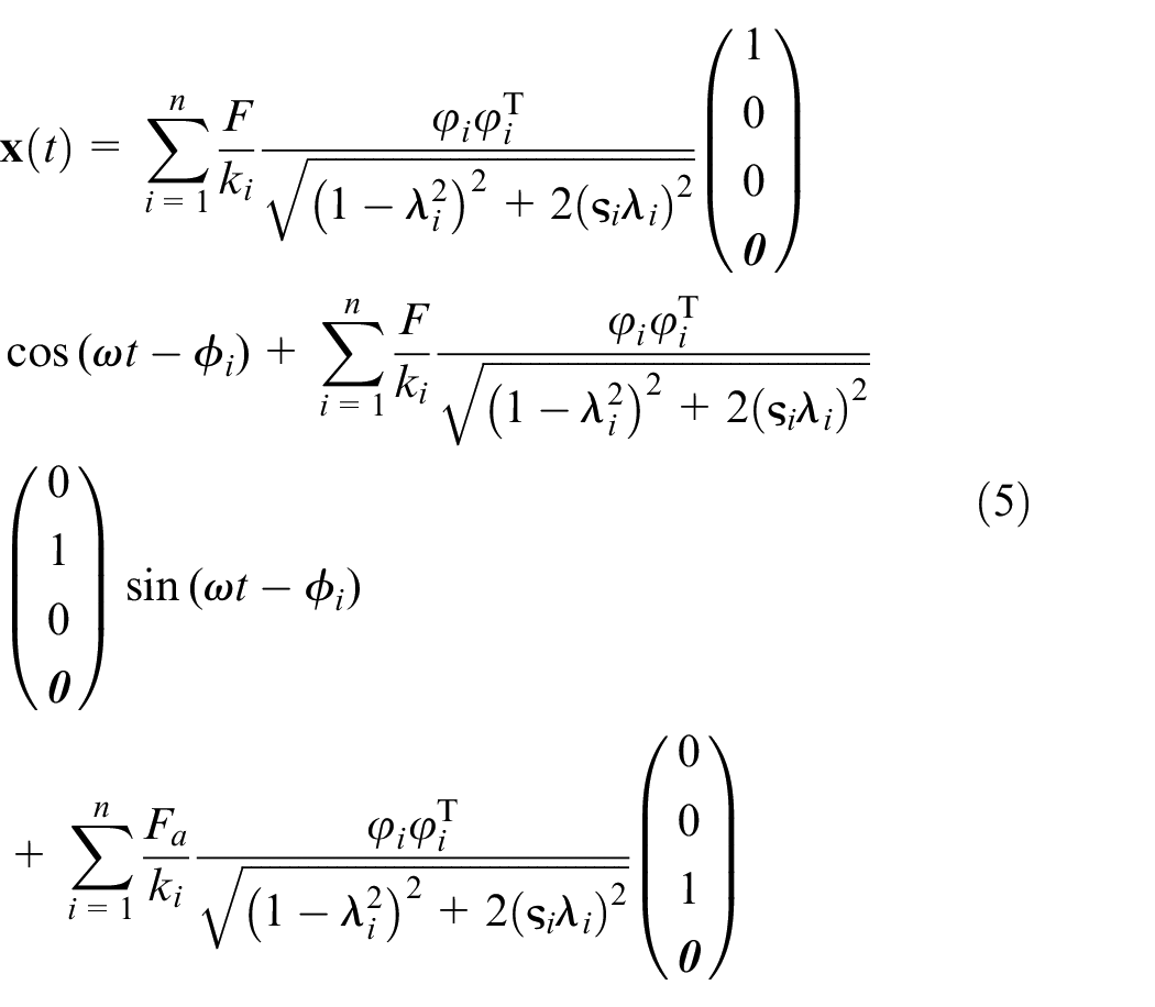
where tan ϕi = 2ςiλi/(1 − λi2)2, and ki = ωi2 denotes the ith modal stiffness.
Experimental set-up
As one of the most practical methods for dynamic analysis of complex machine tool structures,11,23 the impulse response test method is widely adopted. In this paper, in order to analyze the robot dynamic characteristics and obtain the robotic vibration response under dynamic loadings, the impulsive hammering modal test method was carried out by LMS Test. Lab, and the corresponding analysis software was used to identify the modal parameters. The experimental set up is showed in Figure 2(b), where the representative vertical position of u = v = 0 mm, w = −320 mm in frame {
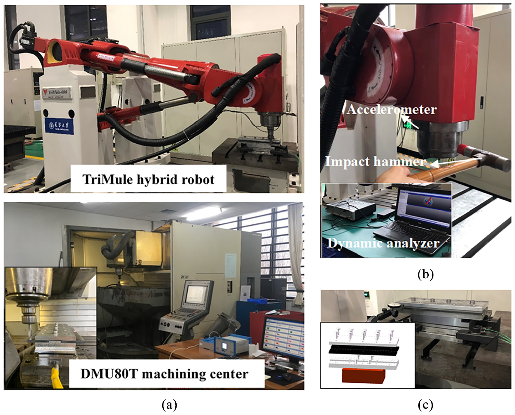
(a) CFRP trimming experimental setup, (b) TriMule hybrid robot modal test setup, and (c) workpiece clamping devices.
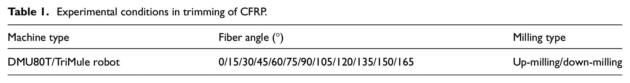
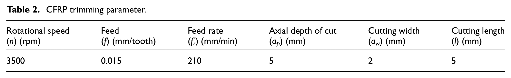
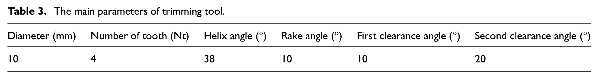
Trimming experiments were carried out with 250 mm × 50 mm UD-CFRP plate using two kinds of machining devices. As shown in Figure 2(a), the first one is TriMule hybrid robot which has mentioned in Section 2, and the second one is DMU80T machining center. Since the vibration of workpiece is also an important factor which affects machining quality, a specific clamping device for CFRP trimming was used to avoid the vibration of workpiece, as shown in Figure 2(c). The experimental conditions and cutting parameters are shown in Tables 1 and 2, respectively. The carbide end mill was selected for trimming experiments, the coating of cutting tool is TiAlN, and the other relative details of trimming tool are shown in Table 3. Three-direction accelerometer was utilized to collect the vibration signals during the trimming experiments. A three-direction dynamometer (Kistler 9275A), supporting amplifier device (5070) and corresponding data acquisition system were utilized to obtain the trimming force signal. The vibration signal of TCP during the trimming process was obtained using the acceleration sensor, and the sampling frequency is 5120 Hz.
Experimental conditions in trimming of CFRP.
CFRP trimming parameter.
The main parameters of trimming tool.
To study the effect of vibration response on the CFRP trimming quality, the surface waviness, surface roughness, and machining damages of CFRP trimming were analyzed for both robot and machining center. The surface profile data and the surface waviness were obtained by Taylor Hobson profiler. Surface scanning was conducted to obtain the 3D profile and roughness parameter of machined surface using a Confocal Laser Scanning Microscope (CLSM) LEXT with a scanning area of 2567 μm× 2580 μm. Each measurement was performed three times and the average values were taken for following analysis. Ultra depth of field electron microscope and SEM were used to evaluate the machined quality. Machined region was also observed by industrial X-ray CT scan system to obtain the corresponding sub-surface damage.
Results and discussion
Vibration response during CFRP trimming process
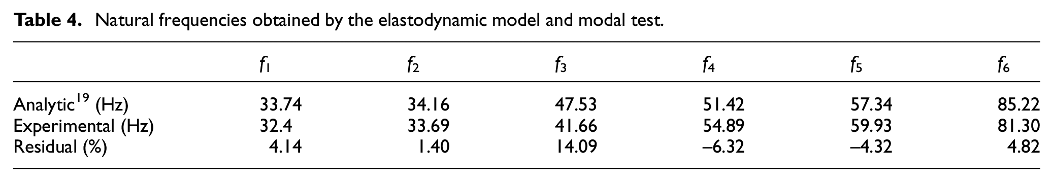
To validate the accuracy of proposed TCP vibration response prediction method, setting the simulation parameter in equation (4) as those of the TriMule prototype. Then the lower-order natural frequency and corresponding mode shapes are evaluated and then compared with the results obtained by modal tests. Table 4 shows the comparison of natural frequencies obtained by the elastodynamic model proposed by Wu et al. 19 and modal test. It shows that the maximum discrepancy of lower-order natural frequencies between predicted and experimental results is 14.09%.
Natural frequencies obtained by the elastodynamic model and modal test.
Justified by above comparison, the robotic vibration response during trimming process can be predicted with confidence by applying the cutting force data in the TCP as mentioned in Section 2. Firstly, cutting forces are the direct reason for the deformation and vibration of the hybrid robot end, hence, the mean values of CFRP trimming for both TriMule hybrid robot and DMU80T machining center with different fiber angle are shown in Figure 3. Based on the above experimental results, it can be found that the mean value of cutting force in three directions is mainly determined by the fiber orientation. Meanwhile, it can be found that there is little difference between the mean values of the cutting force in three directions of hybrid robot and machining center when the fiber angle is lower than 90°. For the larger fiber angle, the trimming force (Fy, Fz) for TriMule robot is slightly larger than trimming force of machining center. This might be caused by the overcut as a result of larger vibration response for the robot based trimming.
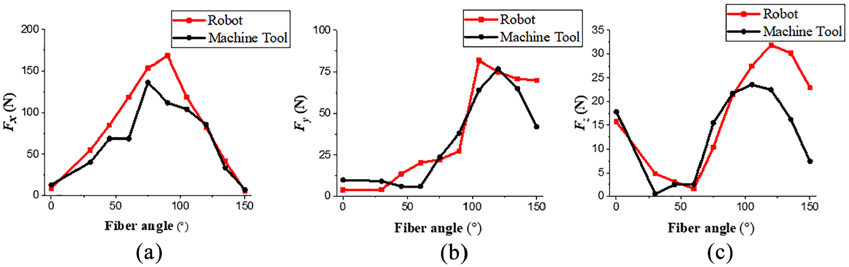
Milling force for TriMule robot and machining center: (a) x direction, (b) y direction, and (c) z direction (dynamometer frame) (n = 3500 rpm, ap = 5 mm, f = 0.02 mm/tooth).
Because of the anisotropic properties of CFRP, the fiber angle is an important factor that affects cutting force, therefore, the robotic vibration responses under different fiber angle for robotic trimming need to be investigated as well. Figure 4 shows the comparison of acceleration response between analytic model and experimental vibration signals collected by sensors of TriMule robot in x and z directions. It can be concluded that analytical results are agreed well with experimental vibration signals. Figure 5 shows the variation of vibration amplitude of TCP displacement response with fiber angle between analytical and experimental results in cutting plane. It is presented that the amplitude of TriMule robot vibration during the CFRP trimming is not only dependent on the fiber angle but also milling type. As presented in Figure 5(a), for up-milling, vibration amplitudes get its maximum at θ = 165°. Meanwhile, Figure 5(b) shows that the vibration amplitudes for down-milling keep a high level when fiber angle is close to 90° (the fiber angles interval of 75°–105°).
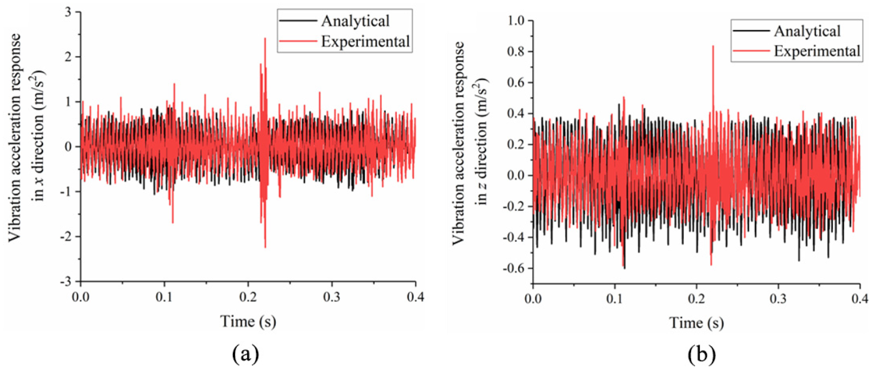
Acceleration response obtained by analytical method and experimental results: (a) x direction and (b) z direction (up-milling, θ = 135°).
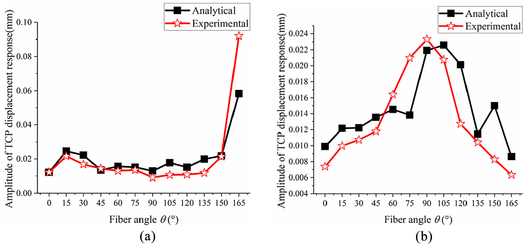
Variation of amplitude of TCP displacement response obtained by with fiber angle: (a) up-milling and (b) down-milling.
Chatter analysis during the CFRP trimming process
Machining chatter has a significant influence on robotic dynamic response. When chatter occurs, the magnitude of vibration will increase significantly. Thus, the cutting force and its frequency spectra during CFRP trimming are analyzed by fast Fourier transforms (FFT). Figure 6(a) and (b) show the cutting force signals in radical direction during up and down milling of different fiber angle CFRP laminates for DMU80T and TriMule robot. It can be found that the amplitudes of trimming force for TriMule robot are significantly larger than DMU80T. This result is the same as published observation results in paper. 5 This can be explained by that the DMU80T enables a more rigid cutting system than TriMule robot, and more energy can be applied to workpiece material removal and small cutting force amplitude is obtained compared with TriMule robot. Thus, the greater cutting force amplitudes might be one of the reasons for the significant vibration amplitude increase for robotic milling process as shown in Figure 5.
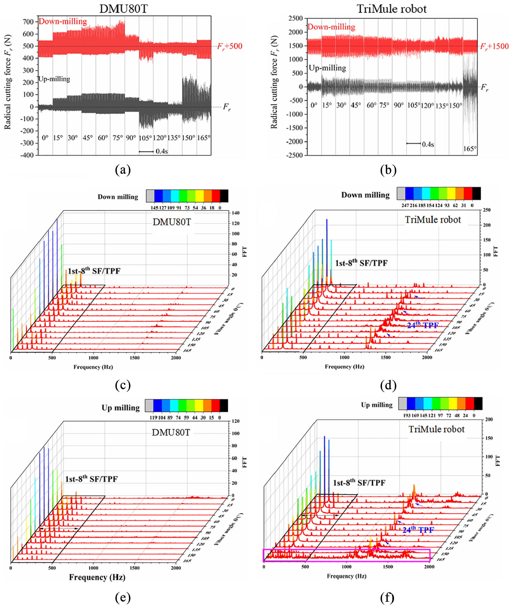
Trimming force signals and corresponding FFT results: (a), (b) cutting force signal for both DMU80T and TriMule robot and (c)–(f) FFT analysis results for CFRP trimming.
The spectral analysis results of CFRP trimming force in the radical direction for both up and down milling are obtained using fast Fourier transforms, as shown in Figure 6(c) to (f). For milling process, the spectra and peak values are primarily dominated by the spindle frequency (SF=n/60 Hz), tooth passing frequency (TPF = Zn·SF), and their higher harmonics. 24 As far as frequency structure of SF/TPF and their harmonics were concerned, the obvious similarities of FFT spectral lines of cutting force signals at different fiber angle seemed remarkable. It is also observed that the frequency dominant pecks of robotic milling have a bigger amplitude and an extra high-frequency component around 24th TPF for all fiber angles. In contrast, only one main band of dominant peak of spectral lines (1st–8th SF and TPF) were observed for DMU80T. Therefore, it can be concluded that the greater vibration response during robotic milling will lead to an extra distribution of spectral lines at high-frequency zone.
From the details of FFT analysis on the cutting force for robotic up milling when θ = 165°. It can be found that the dominant peak of spectral line occurs at not only SF/TPF and their harmonics but also around the natural frequency of TriMule robot. As shown in Figure 6(b) and (f), it was indicated that chatter occurs in this situation and the corresponding vibration and cutting force will be increased dramatically. However, FFT results show that chatter does not occur when θ = 165° during down milling for TriMule robot. The result is consistent with stability analysis conclusion in Pan et al. 25 that up milling is more likely to cause machining chatter than CFRP down milling. The modal coupling chatter analysis for up and down milling under typical fiber angle of CFRP laminates is shown in Figure 7. The thin blue line denotes the smaller stiffness value of robot structure and the thick one represents the larger stiffness value in the figure. According to conclusions of Pan et al., 25 it will more easily induce the modal coupling chatter when the direction of smaller stiffness of machine system is located between the region decided by normal direction of workpiece surface (N) and resultant cutting force (F), as shown the gray zone in Figure 7. The gray region represents the possible unstable region where low-frequency chatter is likely to occur when the axis of smaller robot stiffness lies within this region. It is noted that the possible unstable region for up milling is apparently greater than down milling in TriMule robot trimming process. As a result, down-milling is preferred in robot-based CFRP trimming to avoid the vibration increase dramatically due to chatter occurs.
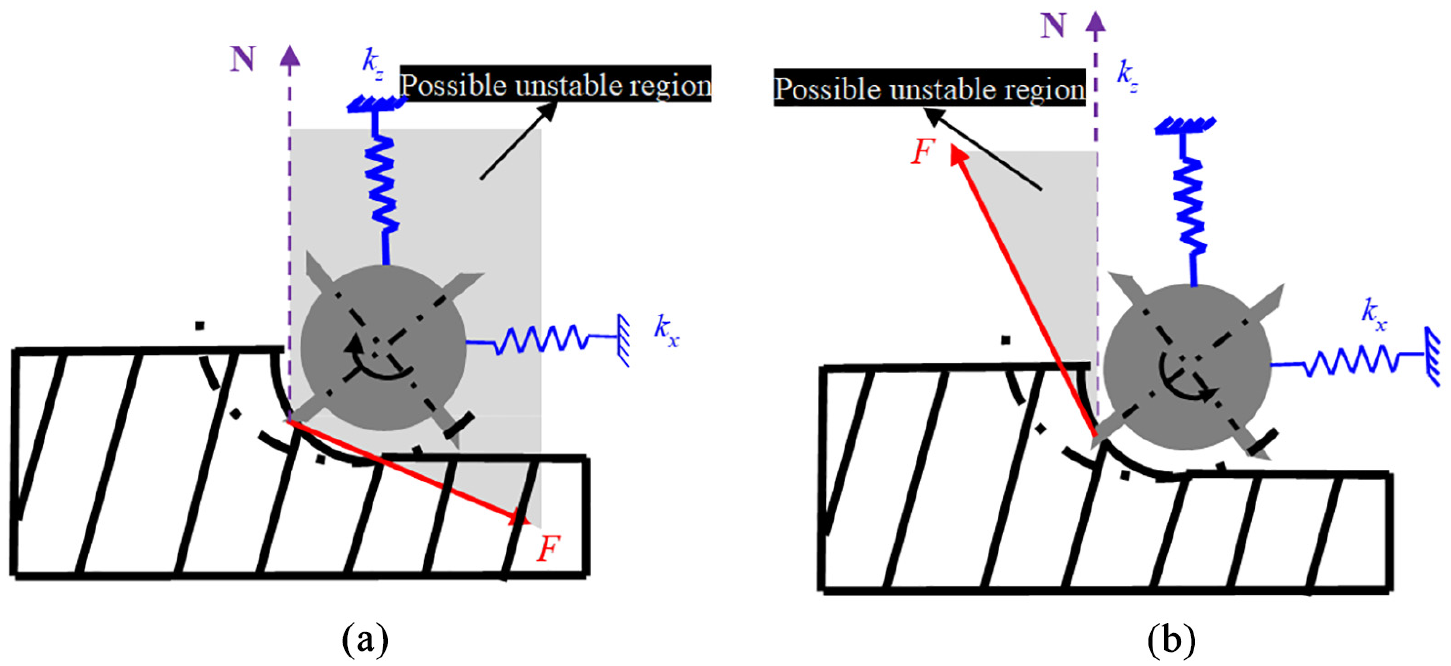
Illustration of chatter analysis of different milling types for TriMule robot: (a) up-milling and (b) down-milling.
Effects of vibration response on CFRP trimming quality
Figure 8(a) shows the comparison of the machined surface optical micrographs between TriMule robot and DMU80T under different fiber angle in UD-CFRP edge trimming. The machined surface was observed every 15° fiber angle interval, and a 50× magnification was selected. From the observation results, it can be concluded that fiber orientation is an important factor in determining the CFRP trimming surface quality. For both DMU80T and TriMule robot, severe surface defects mainly occur in the against fiber cutting region (105° ≤ θ < 180°) for both up-milling and down-milling operations, and no severe machining damage was observed under the along fiber cutting conditions (0° < θ ≤ 90°). To better understand the influence of vibration on machined surface quality, the surface profile and machining damages are investigated as well.
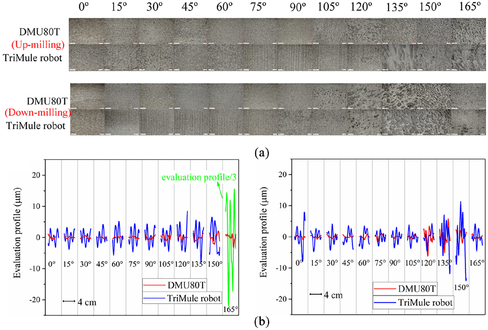
Comparison of machined surface morphology between DMU80T and TriMule robot: (a) machined surface optical micrographs and (b) surface evaluation profile.
Figure 8(b) shows the comparison of machined surface evaluation profile between DMU80T and TriMule robot under different fiber angles with a 4 cm sample length. It is presented that the evaluation profile for robot is dominated by larger amplitude and higher frequency components comparing with DMU80T machined surface morphology. It is indicated that robotic vibration has an influence on machined surface topography, which can increase the frequency and reduce the wavelength of machined surface topography structure compared with DMU80T machined surface. It is also showed that the surface evaluation profile for TriMule robot has a greater amplitude which means that the unevenness degree of surface for robotic milling is greater due to the bigger vibration response.
Surface machining damages for the CFRP materials are more likely to generate in the against fiber cutting region where the fiber-matrix debonding is dominated in this cutting condition, 26 as shown by the SEM picture in Figure 9. From the observation results, more severe machined surface damage (fiber-matrix debonding) occurred for TriMule robot when θ = 135°. To further study the relationship between vibration response and machined surface quality, the size of surface damage in the selected machined surface (7272.73 μm × 5454.55 μm) for both DMU80T and TriMule robot are calculated using Image J. The measurement was conducted at three different positions and its average value was calculated for analysis. Besides, to evaluate the surface waviness, the arithmetical mean deviation of the assessed profile (Wa) was selected as a comparative index in this study. Area of surface damage in against fiber cutting region and surface waviness evolution for both DMU80T and TriMule robot are shown in Figure 10. It is observed that TriMule robot has a higher Wa and larger surface damage area than DMU80T for all experiments. The maximum of area of surface damage and waviness can be observed at θ = 165° for up milling (3,57,271 μm2 and 1.02 μm for DMU80T and 2.64E7 μm2 and 28.645 μm for robot, respectively) and θ = 135° for down milling (1.31661E6 μm2 and 1.81 μm for DMU80T and 1.86029E6 μm2 and 3.23 μm for robot, respectively). Moreover, it is noted that the value of Wa and area of surface damage for robotic up-milling when θ = 165° are larger than other fiber angle. It is also viewed that the robotic vibration response also gets its maximum at θ = 165° during up milling, as shown in Figure 5(a). Apparently, the machined surface damage and waviness has a positive correlation with the robotic vibration response during milling of CFRP.
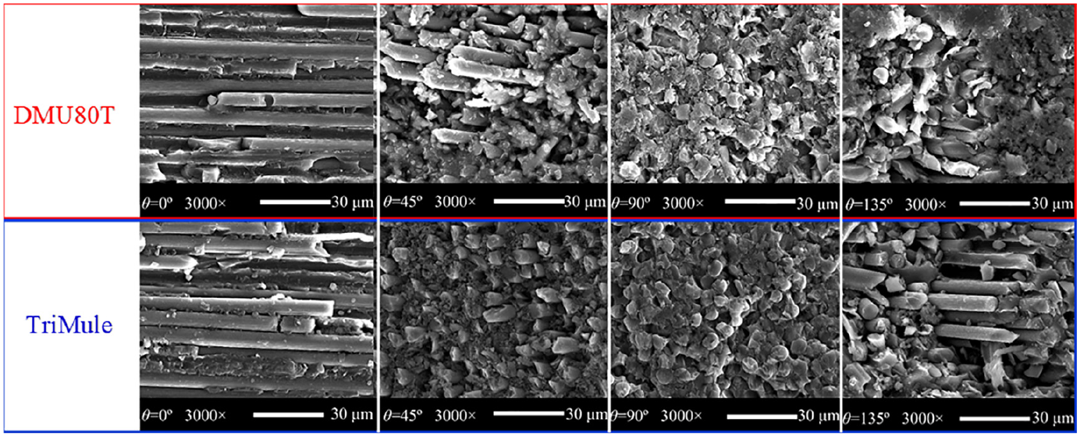
SEM micrographs for both DMU80T and TriMule robot CFRP trimming surface.
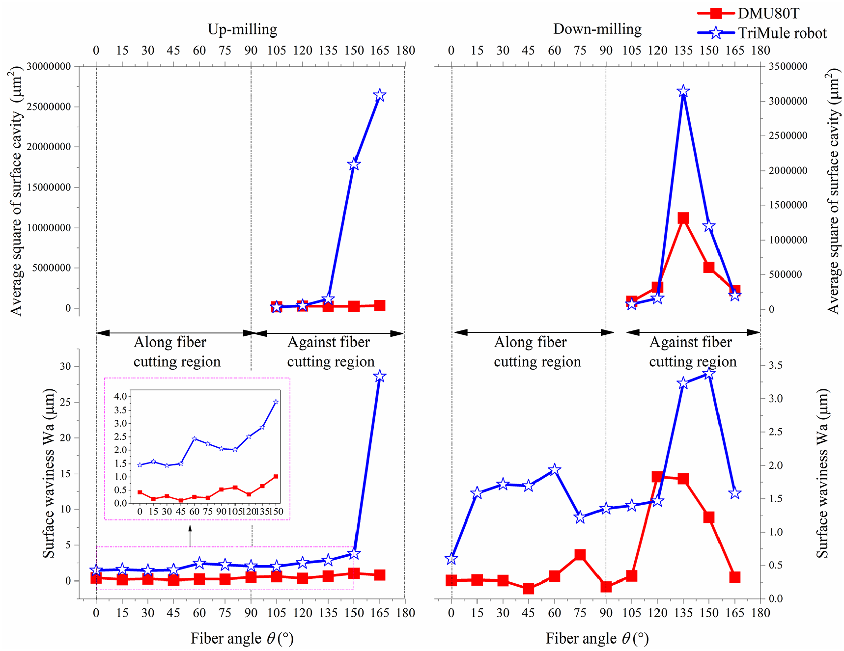
Variation of machined surface damage and waviness with fiber angle for DMU80T and TriMule robot.
Figure 11(a) shows the 3D profile of machined surface for TriMule robotic during down milling when θ = 135°, and the variation of surface roughness for both DMU80T and TriMule robot during down milling were shown in Figure 11(b). It can be found that the surface roughness of machined surface between DMU80T and TriMule robot is almost the same. This results are in agreement with Slamani who notes that 2D measurement of surface roughness, Ra and Rz, have no obvious difference for DMU80T and industrial robot during CFRP machining. 27
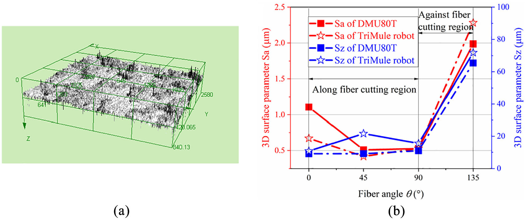
(a) 3D surface profile for robotic down milling (θ = 135°) and (b) surface roughness variation for both DMU80T and TriMule robot (down milling).
The influence of vibration response of TCP on the subsurface damage was also investigated. The X-ray CT scan experiments for CFRP workpiece (total thickness d = 5 mm) were conducted by NanoVoxel 3000 with 5 μm vertical resolution. Figure 12 shows the CT image at a certain depth (Δd) for two typical fiber angles, and the depth of affected zone (Δh) was measured by Image J.
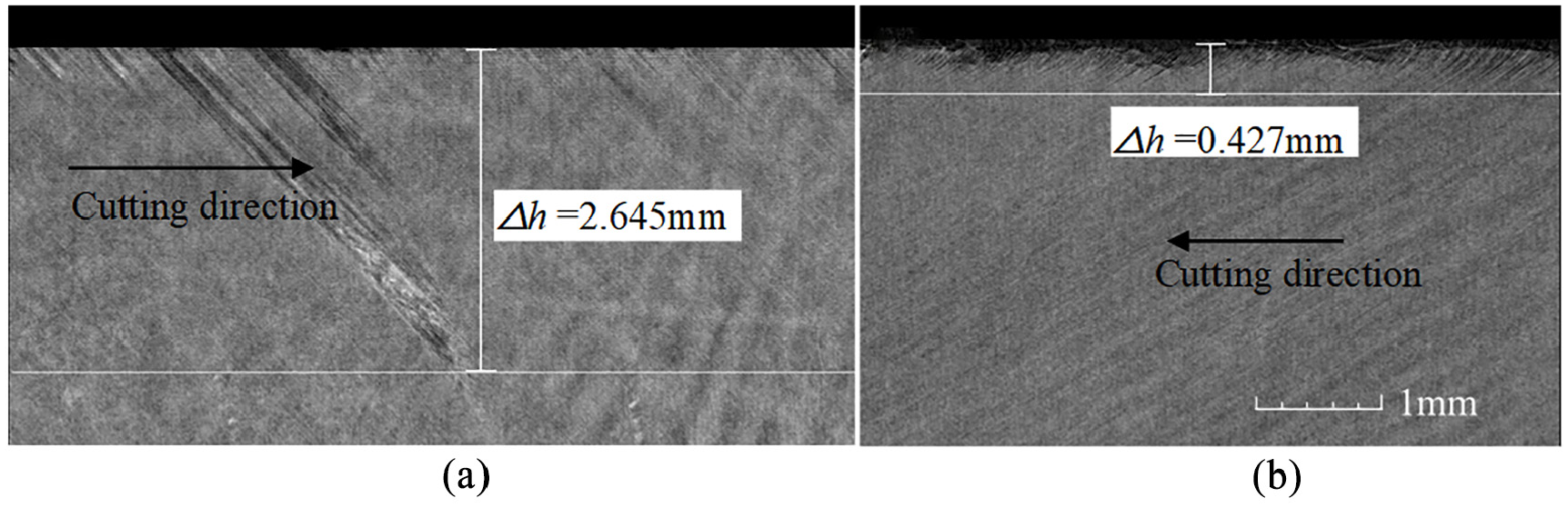
Industrial CT images of machined CFRP: (a) θ = 135° (Δd = 0.05 mm) and (b) θ = 150° (Δd = 3 mm).
Figure 13 shows fitted polynomial plots of Δh versus Δd of CFRP laminates for machining center and robot in different fiber angle. It can be observed that Δh decreases with increasing of Δd and obtains its maximum value in the CFRP laminates top layer (Δd = 0). The reason is that some other machining defects, such as fiber burrs or delamination, occurred at the CFRP laminates top layer, which will increase the depth of affected zone. Besides, the fiber angle is a significant factor for variation of Δh and Δd. From the observation results, it was indicated that the subsurface damages only occur in against fiber cutting condition, the depth of affected zone is minimal (close to zero) for the along fiber cutting condition even when θ = 90° and 105°. However, for θ = 135° and 150°, the subsurface damage can be observed in the entire workpiece thickness (Δd = 0–5 mm). Under this cutting condition, the bending-induced fiber fracture is dominated, which can easily induce the severe fiber-matrix debonding in the chip formation process. In addition, it should be noted that Δh and Δd of CFRP laminates maintain a high-level for robotic trimming comparing with DMU80T which was affected by the larger vibration of TCP during robot trimming process.
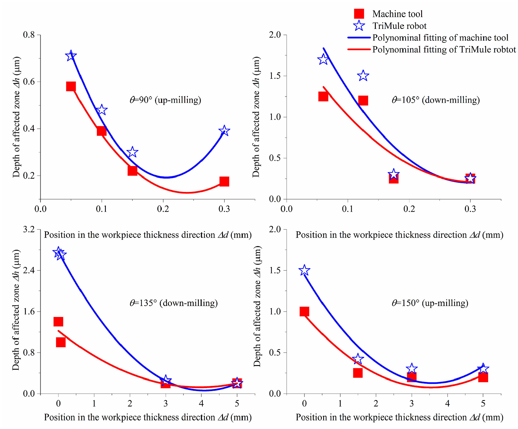
Fitted polynomial plots of Δh versus Δd for DMU80T and TriMule robot.
Conclusions
The objective of this study is to obtain the TCP vibration response and investigate its influence on the machining quality of TriMule hybrid robot-based CFRP trimming for different fiber cutting angle. The general TCP vibration response prediction method is proposed and verified. Besides, the links between the vibration response and CFRP machined surface are studied by comparison of the machining quality between hybrid robot and NC machining center. The following conclusions are drawn from this study:
The effectiveness of the proposed TCP vibration response prediction method has been validated. From the comparison between the analytical and experimental results, it was indicated that the robotic vibration amplitude is critically dependent on the fiber angle and milling type.
The vibration amplitudes get maximum when at θ = 165° for up-milling and keep a high level when fiber angle is close to 90° for down milling during CFRP trimming. Besides, robotic low-frequency chatter was observed for θ = 165° when up milling is employed and in order to lower the cutting fore and vibration response, down-milling is preferred in robotic cutting process.
It is indicated that the great vibration amplitude of hybrid robotic trimming compared with DMU80T will result in a more severe surface and subsurface damage, and larger surface waviness. However, 3D parameters of surface roughness, Sa and Sz, have no obvious correlation with vibration response for the CFRP trimming.
Footnotes
Declaration of conflicting interests
The author(s) declared no potential conflicts of interest with respect to the research, authorship, and/or publication of this article.
Funding
The author(s) disclosed receipt of the following financial support for the research, authorship, and/or publication of this article: This work was supported by National key research and development program of China (grant number: 2017YFE0111300) and National Natural Science Foundation of China (grant numbers: 51705358, and 51775373), and Natural Science Foundation of Tianjin (grant number: 17JCQNJC04700).