
Abstract
Sheet metal forming processes for manufacturing truncated cones can be divided into methods which use shape related tooling to produce the required form, for example, spinning and deep drawing, and processes that utilise kinematics to produce the required geometry, for example, roller, air and swivel bending. Such kinematic forming methods can achieve high degrees of forming flexibility but require process models to avoid elaborate trial and error approaches. For the incremental manufacture of cones, CNC swivel bending as yet lacks such a process model. In addition, with the current ‘state of the art’ processes, the manufactured cones exhibit geometric defects with respect to concentricity and skewing. In this study, the operation of a CNC bending machine fitted with an upper beam that can be inclined was investigated. The proposed inclination of the beam corresponds to the desired conical shape of the product. The machine was provided with a radial sheet feed mechanism (back-gauge) to feed material in even segments between bent corners thus avoiding geometric imperfections. A plasto-mechanic process model was developed to deliver the process parameters for swivel bending of specific conical geometries. The process model was validated by numerical simulations and practical bending experiments. Coarsely segmented conical shapes can be manufactured using the analytically calculated process parameters. For conical geometries, the process modifications of sequential swivel bending showed satisfactory improvements in the initial bending defects, that is, lack of concentricity and skewing. Compared with the target geometries, a tendency towards larger diameters remained in the experiments and is explained by the boundary conditions of the sequential process and if a larger number of bending increments is carried out. The present study delivers a first approach to determine the process parameters for the sequential operation of a swivel bending machine in order to provide relevant process parameters for the industrial production of conical components.
Keywords
Introduction
Conical products find various applications in diverse industrial branches. For example, they are deployed as funnels for fluid materials, connecting pieces between pipes with different diameters, furniture parts, covers or housings in plant and container construction. In addition, they find more advanced applications in aerospace, the automotive industry, construction plant, satellites, and wind-turbines. The production of conical sheet metal components is possible using a number of various manufacturing processes, which offer varying degrees of forming flexibility. First of all, shape related forming technologies for conical products from sheet metal, such as deep drawing and projection flow forming/spinning, permit only limited product variation and with manufacturing accuracy dependent on the properties of the sheet materials. After release of force, the component partially regains its initial shape, commonly denoted by the word spring-back.
1
Because of the shape of the tools, which already define the resultant product, no extensive process models are necessary to describe the relation of product geometry and kinematic parameters of the process. For the production of conical parts, deep drawing in particular, is geometrically constrained by a material specific drawing ratio,
1
for example, up to 2.26 for brass.
2
Conical deep drawing is particularly prone to wrinkles appearing in the walls of the component due to limited support in this area. Therefore, the blank holder force is a crucial process parameter, which can be varied over the progression of the forming method and was laid out adaptively by finite element methods successfully by Sheng et al.
3
Another approach to prevent wrinkling is hydrodynamic deep drawing, which was developed as a process variation to sustain the forming operation using pressurized fluids. Regarding the specific process variation of fluid pressure application to the edge of the sheet in addition to the sheet surface,
Kinematic forming processes, on the other hand, are preferable as only one standard tool is required to produce a wide range of products of varying geometries and hence provide greater manufacturing flexibility.
9
Usually, these forming methods would apply to smaller, yet geometrically diverse batch sizes, as equipping and setting the machine as well as the subsequent forming process itself can potentially be more time consuming, than in the case of shape related techniques, in particular deep drawing. Conical sheet metal components can be manufactured flexibly via process parameters using roller bending.
10
However, the radii are dimensionally limited by the diameter of the bending roller. Rolling of conical parts hence only allows forming of radii larger than the bending roller. To determine the kinematic machine parameters for a given conical geometry, process models were developed for roller bending. Zicke
11
laid the foundations to model the process of asymmetrical three-roller-bending and later on implemented these achievements together with Ludowig
12
in a fully automated process control. Compressed air or die bending on the other hand provides a highly flexible process for the incremental manufacture of conical shells. For continuous bending on die and swivel bending machines, Finkenstein et al.
13
established process models in a comparative study. In contrast to folding sharp angles, large radius air bending is applied in particular for bigger radii and/or high strength steels. Vorkov et al.14,15 provided analytical process models for a single bend and the continuous operation of large radius air bending, also known as bumping. Computational models were successfully applied, for example,
For the incremental operation of swivel bending machines, no analytic process model has been developed yet. The current lack of a theoretical definition thus represents the research gap covered in this paper. Swivel bending is in particular useful for the flexible production of conic profiles with diverse conical geometries, since the use of shape specific tools is not required. 17 For the conventional continuous folding operation, analytic process models 18 and FE simulations 13 have been presented in literature. In the particular case of incremental in-plane swivel bending, a first approach has been established – based on dimensioning the process parameters pivot position, 19 clamping force 20 and tool travel. 21 However, up to now, the production of cones by means of swivel bending has been carried out exclusively by an empirical determination of the kinematic process parameters based on machine operator experience. 17
Background on swivel bending(folding)
With conventional CNC swivel bending, also known as folding, usually a relatively sharp angle is bent in the sheet metal blank. Figure 1 shows a schematic representation of the process in cross-section.
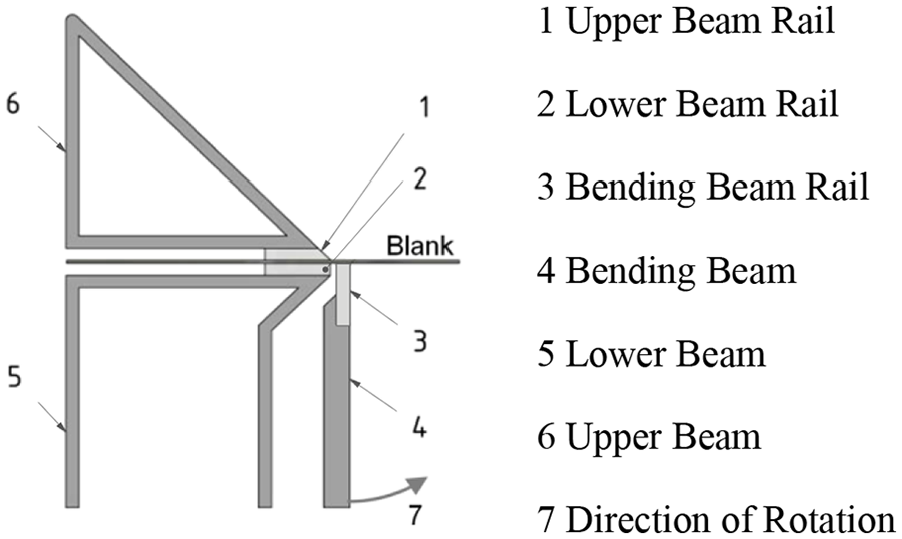
Schematic representation of the swivel bending process.
The tooling consists of the three basic tools, namely the upper, lower and bending beam. Initially, pressure is applied from the upper beam to clamp the blank against the lower beam. By the rotation of the bending beam, a bending moment is applied to the blank, which wraps around the edge of the upper beam. The beams are usually equipped with tool inserts called rails, which are made from special alloyed tool steels and can be exchanged as required dependent on the specific bending operations.
The manufacturing method can be used flexibly for the production of a wide range of formed components with regard to the diversity of achievable geometric features, see Figure 2, such as folding, 13 hemming 22 or cylindrical as well as conical geometries. 17 Within the constraints of the given frame size of the machine, the bending edge, the cross-sectional geometry and the dimensions of the component determine the major degrees of manufacturing flexibility. The process is suitable for the production of a range from one-off to medium batch quantities and is characterized by a high degree of flexibility and ease of automation.
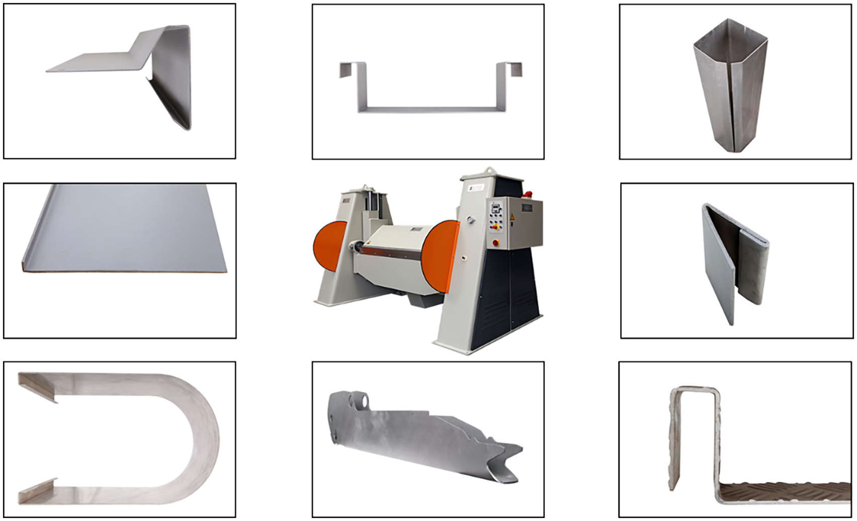
Geometric manufacturing range of CNC bending machines (centre image) according to Hochstrate et al. 17
A sequential operation of the bending process facilitates the production of cylindrical (Figure 2 bottom left) or conical profiles.
State of the art swivel bending of conic profiles in an incremental approach
The current incremental forming method for conical profiles is denoted as the ‘state of the art method’ in the remainder of this paper. With this process, a blank is first cut corresponding to the developed profile of the desired truncated cone. A stationary fixed pivot point is provided on the machine and concentrically aligned to the blank. This constraint allows free rotation in the surface plane of the blank. The translational feeding unit (back gauge) on the bending machine then pushes against the furthermost corner of the blank and the pivot transforms the linear movement into a rotational movement. Subsequently, a relatively small corner is bent in a conventional machine operation representing the first bending increment. Following this, the incremental sequence is repeated, with the blank fed by pushing a constant linear distance alternating with the swivel bending.
Apart from lacking a defined process for the machine operation as given by a process model, the described method reveals dimensional imperfections at the produced cones. The diameter at the top of a truncated cone d is not concentric with the diameter at the base D, which is related to the opening angles at the top (ψ top ) and the base (ψ base ). If manufactured by the initial bending procedure, the angles of a truncated cone open up too wide at the top and too narrow at the base, cf. Figure 3(a). Ideally, these angles should be identical.
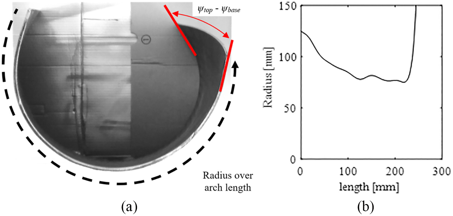
Initially identified bending errors: (a) top view of an example of an open truncated cone. Mismatching opening angles ψtop and ψbase are emphasized by bold lines at the edges and (b) a declining trend of radius over the developed arc length, measured from edge to edge, indicates a skewed profile.
Another problem with the current state of the art technology is the feed axis where constant incremental distances between the individual bends result. With each incremental sequence, the blank component rotates around a fixed point, whilst the back-gauge feeds the blank linearly. This combination leads to variable segment angles of the formed increments, which change along their arc length. This results in a skewing of the open truncated cone, which can be seen in an increasing trend in the distribution of curvature over the arc length, as shown in Figure 3(b). Ideally, the radius distribution along the upper and lower edges of the open truncated cone should be constant.
Objective
The
Assess the method of swivel bending with an inclined upper beam and radial feeding unit for manufacturing improved conical shells compared to the current ‘state of the art’ method,
Develop analytical and simulation models, which relate the process parameters to the emerging geometry for this specific process modification and
Critically, to validate the findings by numerical studies and practical bending experiments.
Methodology
A process model for incremental bending of cones is provided based on geometrical and plasto-mechanical principles. Process parameters were derived with the analytical model corresponding for given target geometries. The model predictions were tested in finite element simulations as well as in practical bending tests. Finally, the nominal, simulated and practically achieved geometries were evaluated.
Material
For the bending experiments, a medium tensile steel grade S235JR in 3 mm sheet thickness was used. The initial material was determined in axial tensile tests in accordance with DIN EN ISO 6892 23 (Table 1).
Material properties of the 3 mm sheet metal type S235JR used.
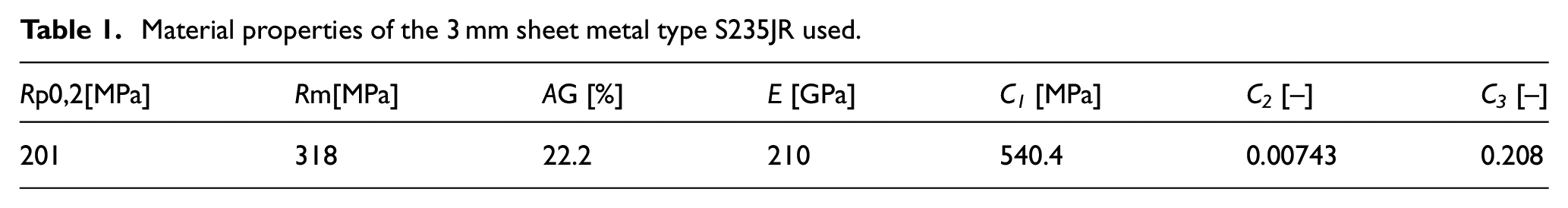
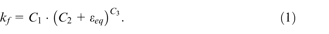
The flow curve was implemented in the finite element simulations based on the exponential hardening law. Flow stress kf is defined according to
Analytical modelling
For the present investigation, partially opened truncated cones were bent from sheet metal blanks. First of all, the geometry of a truncated cone is defined by geometric parameters. The dimensions of interest are shown in Figure 4. The diameter at the top of the truncated cone is designated d and the diameter at the base of the cone D.
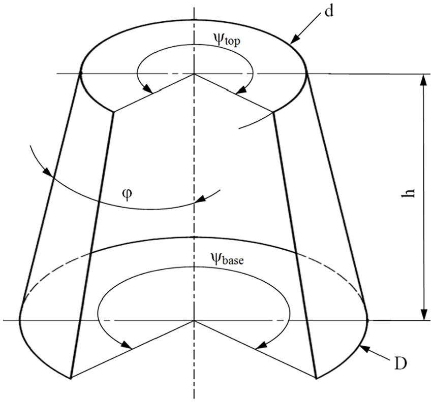
Geometrical parameters of the open shell of a truncated cone.
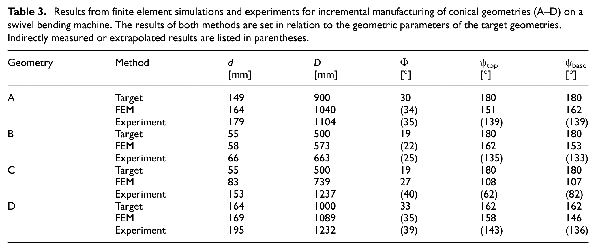
To utilize the derived analytical process model, the forming process and the folding machine must meet the basic requirements described below. It is assumed, that during the bending process, the sheet has tangential contact with each tool of the folding machine (upper, lower and bending beam). Hence, the bending beam is assumed to form the sheet at its surface instead of by edge contact. For this reason, the bending beam must have an adequate depth q. An inclination of the upper beam (inclination angle β) correspondingly to the cone angle
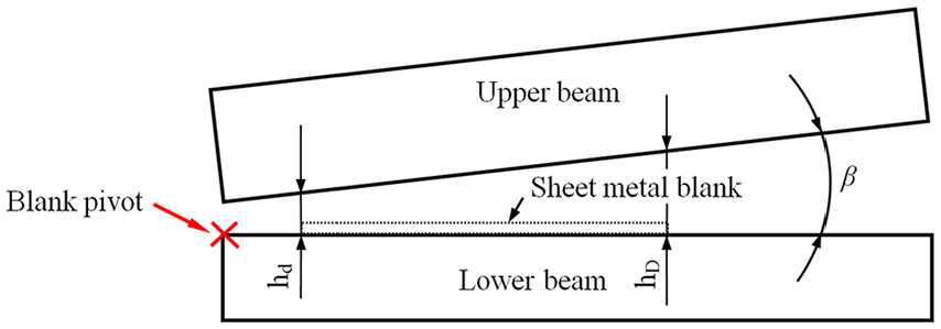
Inclination of the upper beam with reference to the lower beam (front view, schematic illustration without bending beam).
The blank outline needs to be cut to match the developed surface of a given truncated cone’s shell. The blank must be advanced in a radial path around its concentric centre by the machine to bend a consistent cone without skewing. The equations presented in the remainder of this paper relate to the area of continuous bending in the central region. Different geometric conditions may prevail in the initial bends due to the initially flat blank. The model aims for calculating the machine parameters hd, hD and α in relation to the desired cone geometry.
Derivation of the bending radius
At first the outer unloaded radius (after bending) at the base of the cone ro2,b is determined. The model assumes a circular contour of the cone and is represented by a polygonal form with a number n of rounded sides (see Figure 6). n can be chosen as required and will determine the angularity of the bent conical shape. The parameter f′b represents the length of the straight sections of the approximated cone and must be selected within the limits described below. To get a cone as round as possible, f′b needs to be minimized. The cone is thus approximated by alternately curved and straight sections.
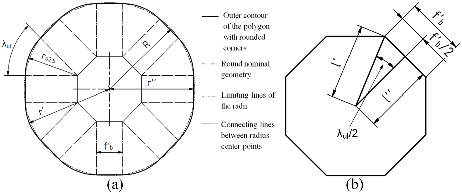
Approximation of the circular contour by means of: (a) a polygon and (b) the associated polygon in the centre.
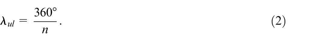
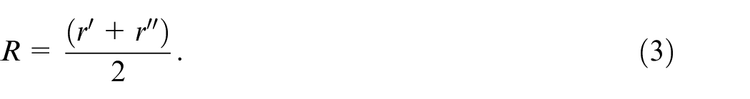
The outer radius R is related to the selected diameter D by R = ½D. In addition, the unloaded angle λ ul is related to the number of edges according to
The desired radius R is approximated by
Considering the relations above, an equation for the unloaded radius ro2,b can be determined. For this purpose, formulas for the radii in the polygon r′ and r″ must be established. These are

and

where
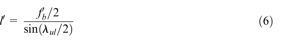
and
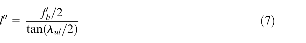
apply.
Inserting equations (4) and (5) in (3) delivers the unloaded radius of a bending increment depending on the size and angularity of the desired conical shape.
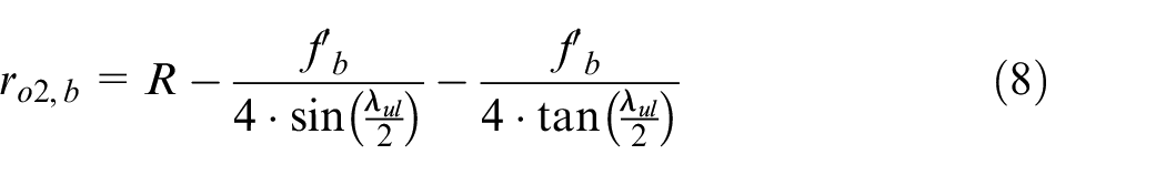
Since ro2,b may become at least zero and not negative, the following limitation for f′b results from (8) assuming ro2,b equals zero:
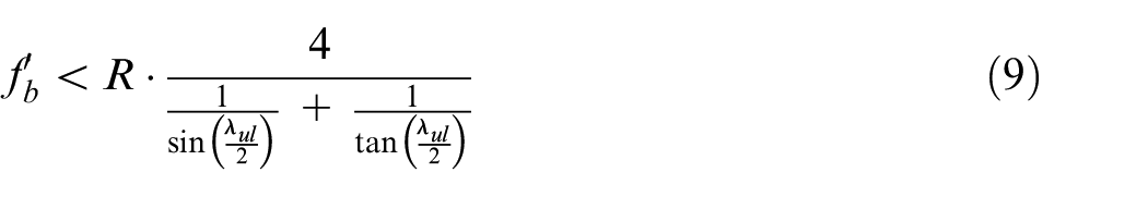
Hence, f′b must be selected between zero and the limit determined by equation (9).
To determine the unloaded radius, the lengths of the straight sections in between the bent segments are derived from the developed surface of an unbent, angular segment (see Figure 7).
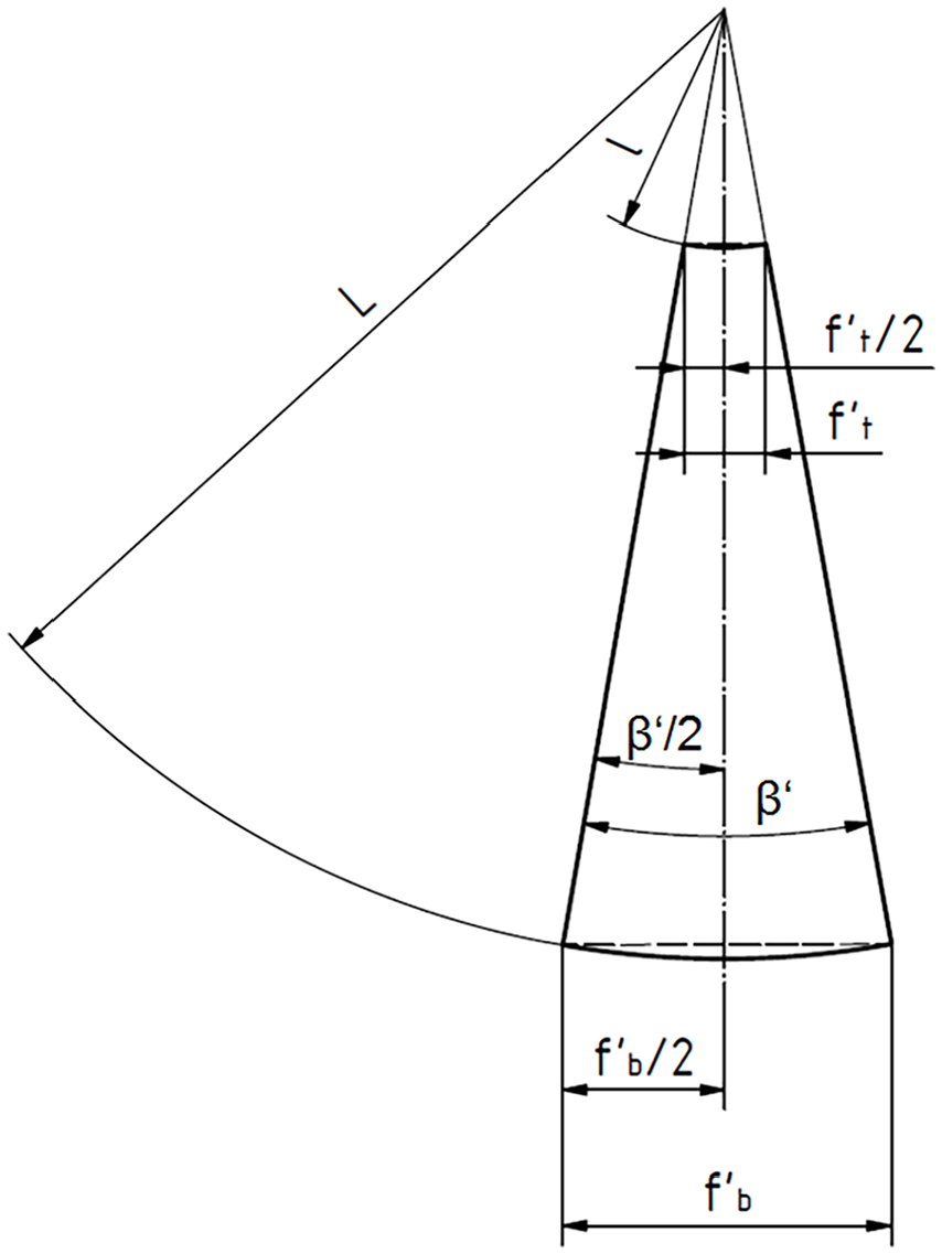
Developed shape of a cone segment with straight section.
The mean diameters of the truncated cone relate to the centre of the sheet thickness s by dc = d – s and
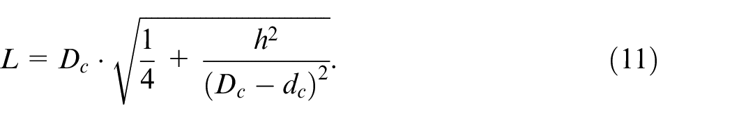
D c = D – s. The radii of the blank shape of the developed cone l and L are calculated by
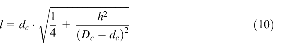
and
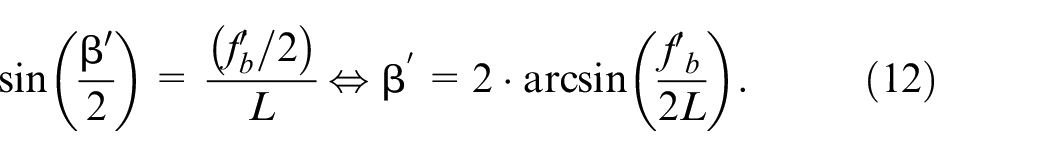
The segment angle β′ is determined by the unfolded outer radius and the straight section of the cone’s outline at its base f′b:
By the trigonometric relationship
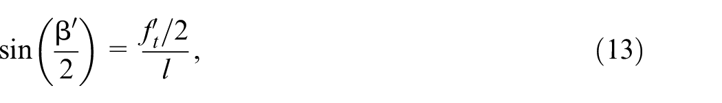
the length of the straight section at the top of the truncated cone f′t is expressed as

Finally, the unloaded radius at the top is defined, similar to equation (8)
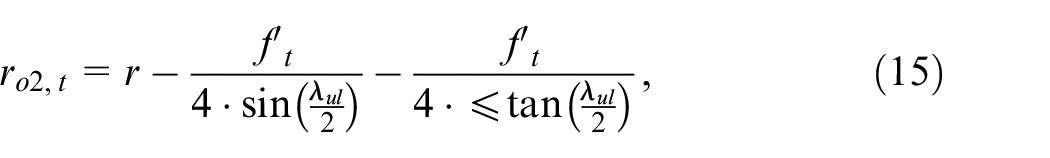
where r = ½ . d applies.
In addition, the mean and inner unloaded radii at the top and base of the truncated cone are required for the following considerations, which, respectively, result from the outer top or base radius minus half the sheet thickness. The incremental bending technique is not necessarily limited to closed truncated cones. The manufacture of many products might require an open conical shell instead, which is described by the opening angle ψ (see Figure 4). Accordingly, for a given angularity of a closed truncated cone with n edges, the number of bends n′ of an open shell relates to
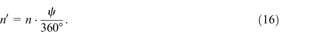
n and ψ should be chosen in a way that only whole numbers and thus complete bending processes are considered for n′.
Calculation of loading radii by spring-back and upper beam inclination
Since the unloaded radii (after bending) are derived, the radii as loaded by the machine during the process can be calculated according to spring-back assumptions following Schilp et al. 26 To calculate the spring-back factor k, the loaded and unloaded radii or the unloaded and loaded angles are set in relation according to Figure 8.
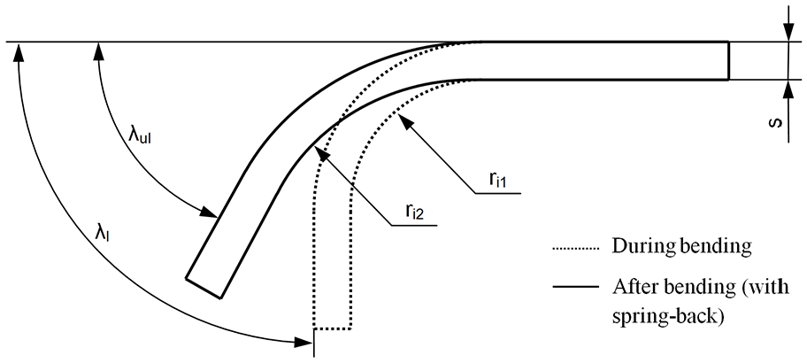
Spring-back of a sheet metal according to Schilp et al. 26
Correspondingly, the spring-back factor relates to
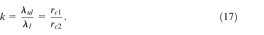
According to Klocke and König, 27 the loaded radius before spring-back is defined as
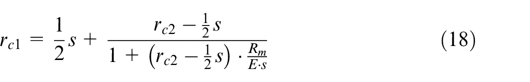
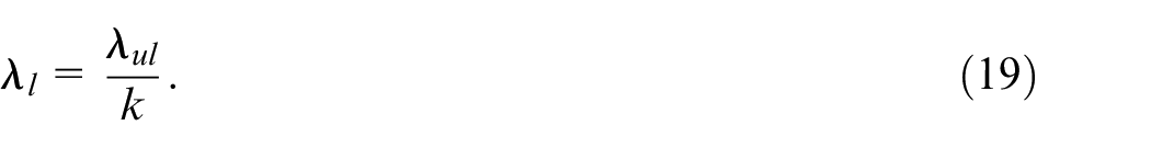
Under consideration of equation (17), the load angle λ l is given as
If the equations above are used to calculate the loaded condition on the upper side of the truncated cone, the radii rc1,t and rc2,t are required. Analogously, rc1,b and rc2,b determine the loaded conditions at the base of the truncated cone. The loaded and unloaded angles must be identical both on the top and on the base.
Calculation of the upper beam’s distances and inclination
Once the loaded radii are determined, the distances between the upper beam and the lower beam can be derived at the edge of the top (hd) and at the base (hD) of the truncated cone (see Figure 5). To determine the upper beams inclination and distances, the positions and dimensions of the other tools as well as the rounded edge of the upper beam need to be parameterized. Namely, these are a, e, c, rub and q according to Figure 9.
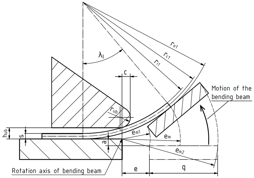
Side view of the machine during bending the sheet, tools shown hatched.
For the model presented in this paper, a = 0 mm was assumed in order to suppress errors, which could be caused by the distance of the bending beam as well as to ensure tangential contact on the upper surface on the bending beam. c and rub are given by the rail used at the upper beam. If tangential contact is assured, e can be selected freely within the specification 0 < em1 ≤ em. With regard to the illustrations of the process model, it should be mentioned that in some cases no distinction is made between the bends at the top and at the base of the cone. Accordingly, the indices t (for top) and b (for base) are missing to keep the figures generally valid for both cases. In the remainder of the modelling section, equations are carried out using the top of the truncated cone (index t) exemplarily.
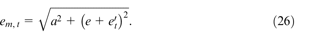
First, the movement ranges of the bending beam, that is, em,t (contact point with the sheet metal), em1 (inside) and em2 (outside), are determined, since these are decisive for further calculations. In this context, the relationships

and
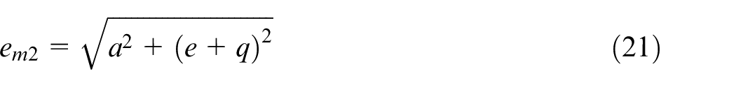
apply. In order to guarantee that the sheet metal rests on the bending beam, em1 < em,t < em2 must apply. In addition, auxiliary dimensions are required for the derivation of em,t which are shown in Figure 10(a).
Side views of the process, shown without upper beam: (a) auxiliary dimensions during bending and (b) principle sketch between lower beam and bending beam illustrating auxiliary angles.
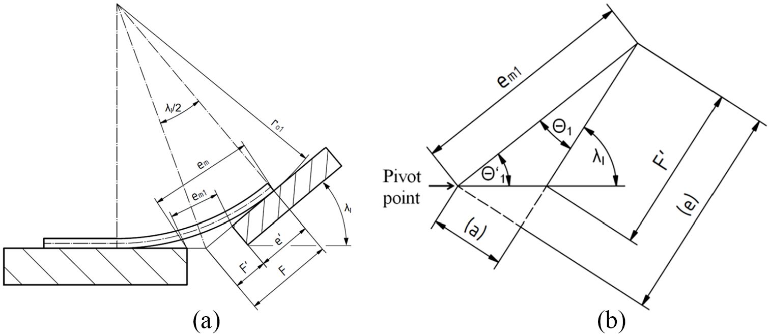
The distance Ft is determined by bisecting the angle of the load angle λ l :
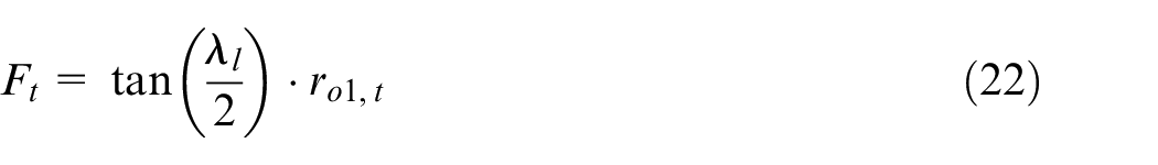
Figure 10(b) illustrates a detailed view of Figure 10(a) between lower and bending beam with auxiliary angles. The angle Θ 1,t is determined by the initial position of the bending beam (see Figure 11(a), dash-two-point line) by the trigonometric equation
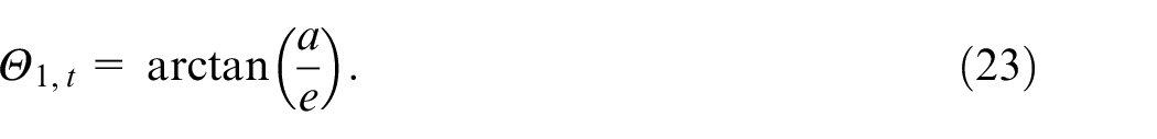
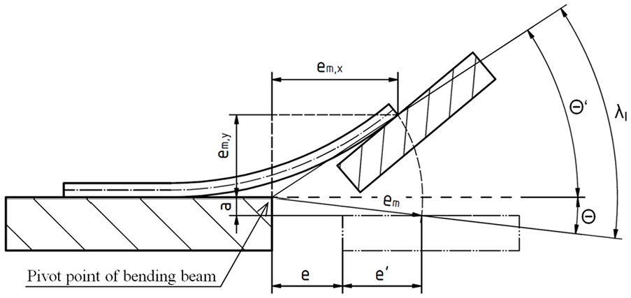
Sketch for the determination of Θ, Θ’ and em,x. Side view without upper beam.
For this purpose, the parameters in the initial position of the bending beam a and e are shown dashed in Figure 10(b). Θ′1 is derived from

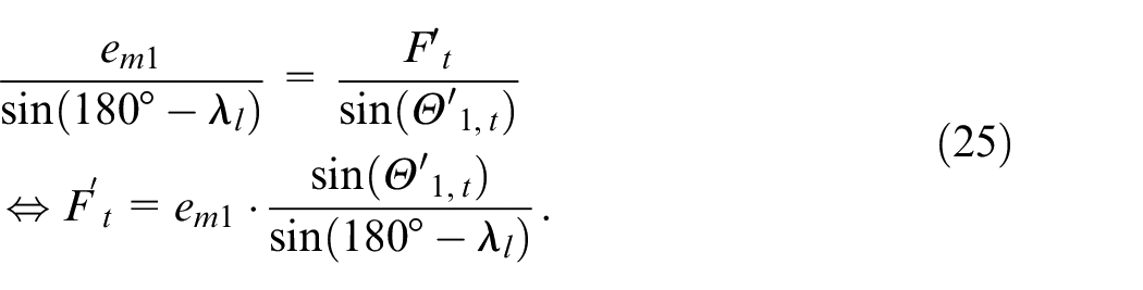
F’t can now be determined facilitating the sine theorem:
As shown in Figure 10, the length e′t denotes the tangential point of contact of sheet metal and bending beam and relates to e′ t = Ft– F′t. Thus, em,t is described by
If the radius em,t is rotated counter clockwise by the angle λ l until the radius touches the lower beam in initial position (double dotted and dashed line), the angle Θ t can be calculated (see Figure 11).The double dotted and dashed line shows the starting position of the bending beam and the dashed lines represent auxiliary lines.
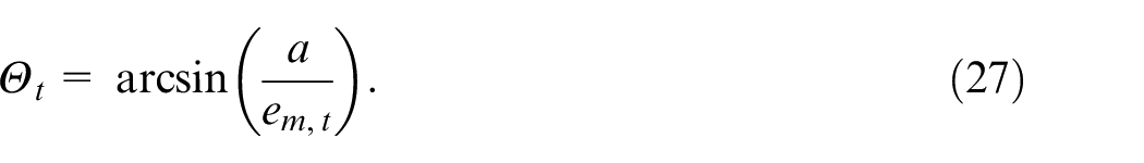
Additionally, Θ′ t = λ l –Θ t can be concluded from Figure 11. The horizontal component of em,t can be calculated in bending position of the bending beam (em,x,t):

The horizontal distance between the centre of the radius of the bent sheet and the point of contact between the sheet and the bending beam in bending position at the top of the cone, represented by the parameter Ot, is additionally required, cf. Figure 12(a).
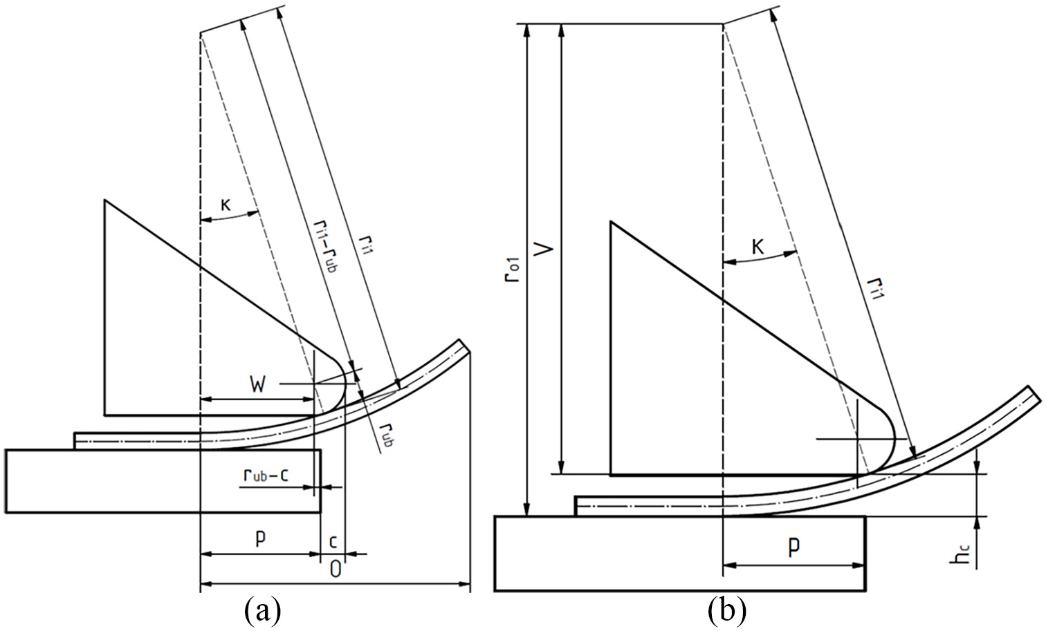
Principle sketch of the upper beam’s area of contact: (a) side view, shown without bending beam for the derivation of horizontal auxiliary dimensions and (b) vertical auxiliary dimensions.
The relation

is required to determine the horizontal distance between the centre of the radius of the bend and bending beam pivot:

In addition, the relation

is derived based on Figure 12. κt represents the angle between the vertical and the point of contact between the upper beam and the sheet metal. κt is determined by the relationship
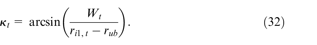
Consequently, the vertical distance between the centre of the bending radius of the sheet and the point of contact between the sheet and the upper beam at the top of the cone Vt can be defined, see Figure 12(b). If the vertical distance Vt between the centre of the bending radius and contact point of the upper beam is known, the distance between the lower beam and the upper beam at the point of contact with the sheet metal hc,t can be determined by


Finally, the distance between the upper and lower beam hd can be represented by the dimension hc,t in connection with trigonometric relations and the radius of the upper beam rub (compare Figure 13).
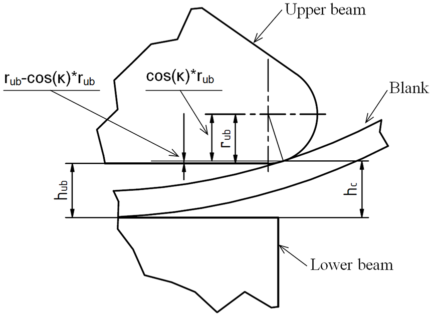
Schematic sketch of the upper beam height hub.
The height of the upper beam at the top of a truncated cone is hence given by the relation

In order to determine the height of the upper beam at the base of the cone, the calculation of equations (23) to (35) apply likewise, whereby the index t must be exchanged for the index b and the variable hd for hD.
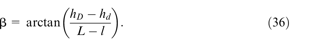
The lower limitations of the upper beam’s heights on each side of the blank have to be chosen in a way to at least guarantee freedom of movement, that is, hd > s; hD > s. Due to the height of the upper beam at the top and at the base of the cone, the angle of inclination of the upper beam β can now be derived. Figure 14 shows the upper beam distances at the top and base of the cone (hd and hD) and the distance at any position hub. The length of the lower beam Llb is determined by the machine.
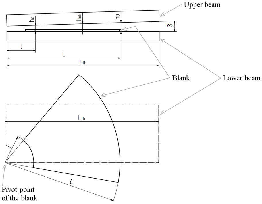
Schematic drawing of the upper beam’s inclination (top: front view of the machine, illustration without bending beam; bottom: top view of the machine, illustration without upper beam and bending beam).
The angle of inclination of the upper beam β can be represented by an inverse tangent function:
Calculation of the incremental bending angle
At this point, the incremental bending angle α represents a remaining, yet unknown machine parameter for the process of sequential bending of conical geometries. Since an angular error occurs when the sheet is raised up until it makes the initial contact with the upper beam, the machine bending angle α does not correspond to the loaded bending angle λ l . Accordingly, with respect to the loaded angle, α is larger by the angle swept over during lifting the sheet without deformation. During normal operation of the swivel bending machine, this fact does not have to be considered, as the blank is clamped between the upper beam and the lower beam. In the case of the presented incremental bending procedure, however, an unclamped condition is necessary to ensure a smooth process. For the hereby derived process model, a distance between the upper beam and the lower beam was hence introduced.
Figure 15 illustrates the angle error ξ when initially lifting the blank before its deformation commences.
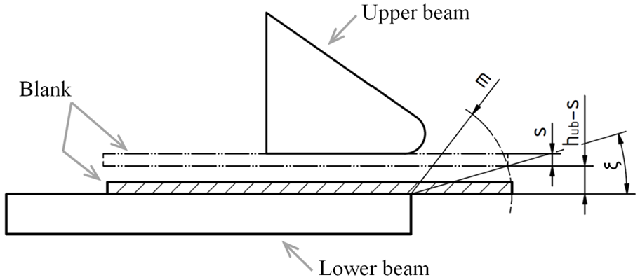
Illustration of the angle error ξ, caused by initially lifting the sheet (lifted sheet is displayed as a double dotted and dashed line).
The sheet metal is moved upwards until it rests against the upper beam. It must be ensured that the lower edge of the sheet, which comes into contact with the bending beam, remains on the radius m after displacement. This results in the angular error ξ. For the determination of ξ, the distances of the contact points mt at the top of the cone and mb at the base of the cone are required, see Figure 16).
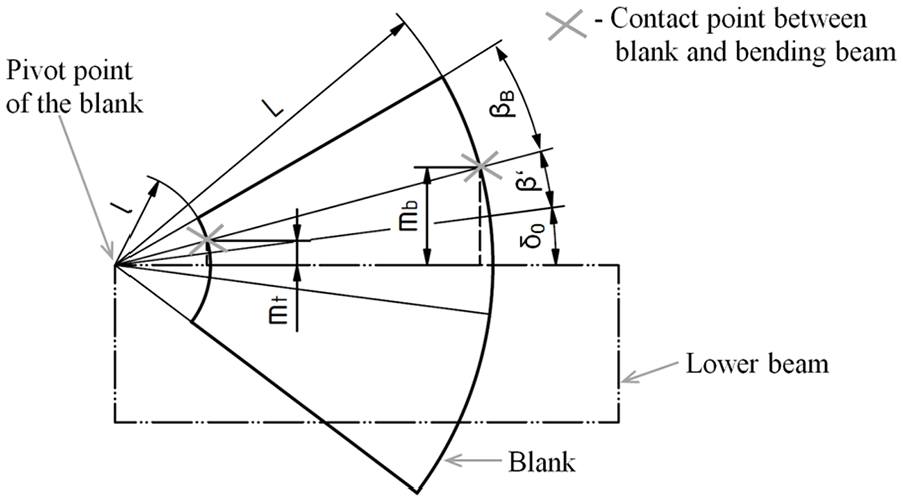
Blank with the contact points on the bending beam (contact points indicated by grey crosses).
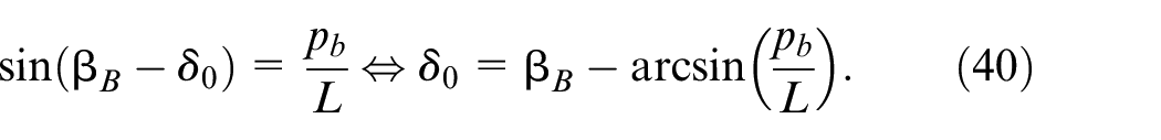
Besides that, the yet unknown angles δ 0 and β B are shown in Figure 16. δ 0 denotes the start-angle of the blank outline in the machine and β B represents the segment angle of the part of the blank to be bent. These angles are calculated from the blank as shown in Figure 17.
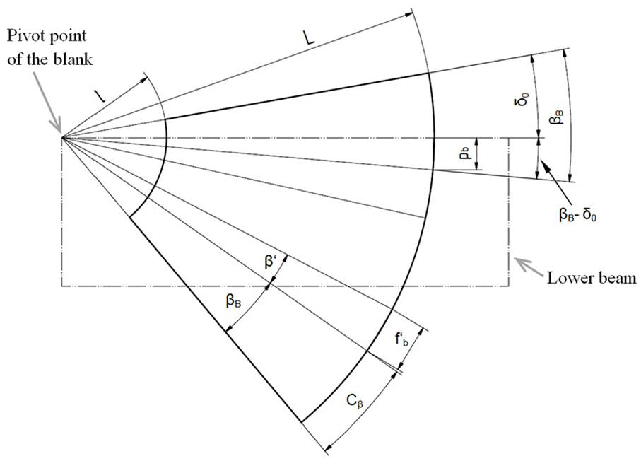
Blank with the relevant data for the calculation of βB and δ0.
The arc length Cβ of the segment to be bent results from
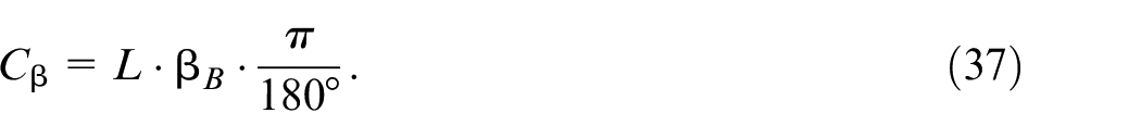
Since the arc length is maintained after bending in the neutral axis,
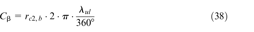
also applies. After equations (37) and (38), βB is obtained as
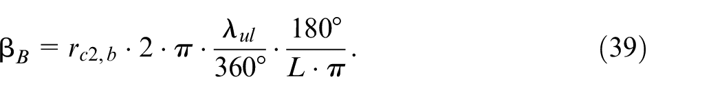
The start-angle δ 0 of the blank is derived by the angle β B
Thus the parameters mt and mb are determined by trigonometric correlations according to Figure 16:


For the top and the base of the truncated cone, the angular errors during the bending beam’s initial lifting of the blank are expressed as
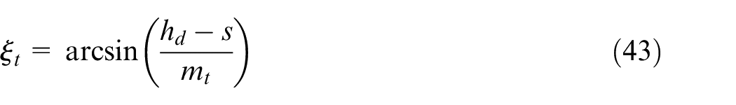
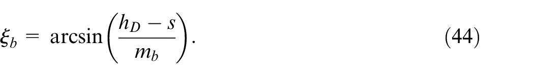
Since the bending beam cannot drive different bending angles lengthwise, the angle error is averaged ξ = ½ (ξ t + ξ b ). The bending angle is the result of the load angle (section 2.2.2) and the angular error:

Thus, the parameters necessary for setting the machine to produce the desired section of a truncated cone are known.
Limitations of the process model
Due to the transition from elasticity to plasticity, the bending process is limited by means of a specific maximum bending radius. In order to achieve plastic deformation, yield stress must be exceeded. Accordingly, Rmax denotes the maximum possible bending radius which must at least be achieved in order for plasticisation to begin. To calculate Rmax, a section of the elastically loaded bent sheet is considered as shown in Figure 18.
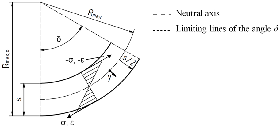
Bent sheet metal detail with stress and strain, elastic condition.
Stress σ and strain ϵ become zero at the neutral axis, which is assumed identical to the mean radius at the centre of the blank thickness. Hence, a constant arc length at the neutral axis can be assumed. The stress for the elastic state is approximated by the equation σ = ϵ·E. Assuming Rp0,2 = σ as yield criterion, ϵ min represents minimum strain. Thus, the two correlations result in

Within the general definition of strain,
in the case illustrated in Figure 18, l0 represents the arc length of the neutral axis with Rmax and the corresponding bending angle δ
Similarly, the stretched length le results from the arc length with the outer radius Rmax,o and the bending angle δ
Facilitating equations (49) and (48) in (47), where ϵ = ϵ min applies, the following relation is obtained:
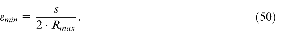
The equation for the strain at 0.2% yield strength is therefore independent of the bending angle δ. In reality, however, the strain is dependent on the bending angle, which affects the accuracy of the analytical model. To determine the maximum bending radius Rmax, equation (50) must be inserted in (46) and converted to Rmax
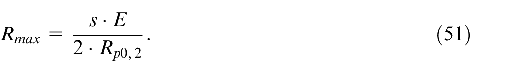
The parameters s = 3 mm, E = 210 GPa and Rp0,2 = 201 MPa were used for this work. This results in a maximum bending radius of Rmax = 1565 mm for the given material.
Validation geometries and process parameters
The validation of the process model, derived in subsection 2.2, was carried out with different conical geometries, namely A, B, C and D. The geometric properties of these cones were chosen in a way that allows the results to be assessed with varying diameters d and D, cone angles
Geometric properties and kinematic process parameters of the experimental cones, hereinafter denoted A, B, C and D.
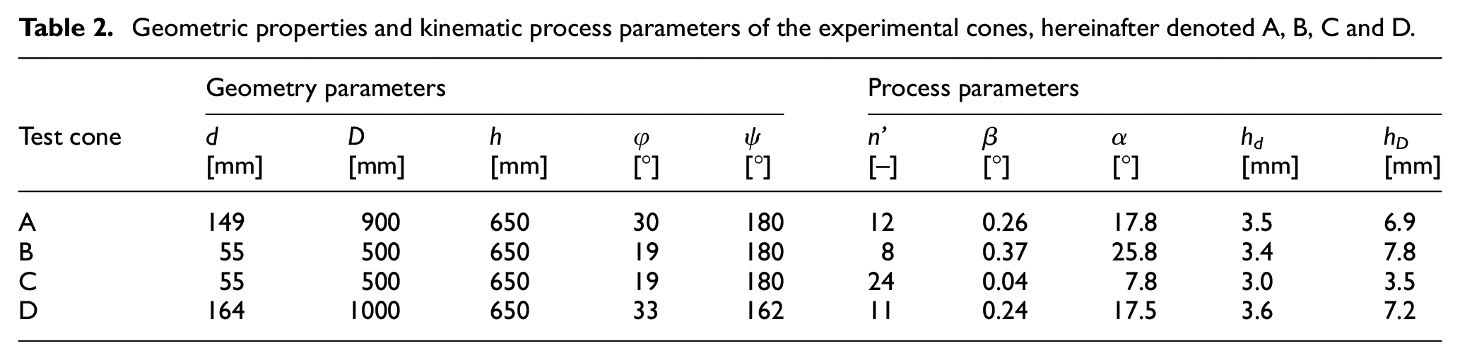
The supplementary machine dimensions of the practical bending experiments were as follows: a = 0 mm, c = 0 mm, e = 2 mm, q = 230 mm, rub = 1.5 mm, Llb = 3050 mm and were implemented in the simulation model accordingly. For the validation in simulation and experiments, sheet metal steel S235JR was utilised with a nominal material thickness of 3mm. Prior to undertaking the experiments, the material was cut into blanks according to the developed profile of each truncated cone. According to equation (51), the maximum feasible bending radius for minimal plasticisation of the materials Rmax = 1565 mm (considering sheet thickness of s = 3 mm). Hence, the diameters of the planned truncated cones according to Table 2 can be bent by the method of sequential swivel bending.
In the following methodological sections, the application of the process parameters, as derived from the analytical model for sequential swivel bending of open shells of truncated cones, is presented with respect to process simulations as well as practical bending experiments.
Finite element simulations
For this study, the simulation program
The incremental bending process of conical shells was simulated in three basic stages. In the first stage, a bending step was performed, in order to simulate the elastic and plastic deformation of the blank resulting from swivel bending. In this explicitly calculated numerical stage, the bending beam swivelled until it reached the desired bending angle α, then stopped and reversed its rotation until it reached its initial position. Hereby, the blank could relax explicitly after the deformation load was released. During the second stage, which was also calculated explicitly, the blank pivoted concentrically to the radii of the developed shape of the cone until it achieved the feeding segment β b , cf. Figure 19(a).
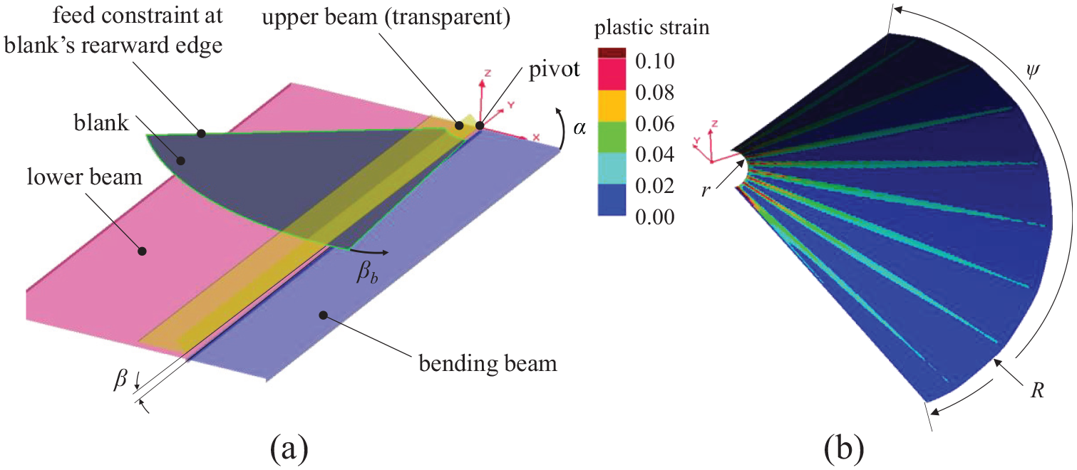
FEM representation of the bending process: (a) Relevant objects and indication of process parameters upper beam inclination β, feeding segment βb and bending angle α and (b) Numerical result of validation study B (according to Table 2) after spring-back step. Indication of resulting geometrical parameters top and base cone radii r and R as well as opening angle of conical shell ψ.
In contrast to physical experiments on a swivel bending machine, in simulation the concentric feeding procedure can be easily implemented by a constraint pushing the rearward edge of the blank in an angular way. Both steps, bending and feed, were repeated sequentially according to the desired number of bends n′.
The simulation procedure closed with a spring-back stage where the blank was released from the tools and locked within isostatic boundaries. The geometrical elastic relaxation associated with spring-back was calculated implicitly by converging towards an equilibrium of residual stresses, which result from plastic deformation. Afterwards, relevant geometric properties of the truncated cones were evaluated from the finite element mesh of the blank according to Figure 19(b).
Bending experiments
In order to validate the kinematic parameters predicted by the analytical process model, practical experiments were carried out. A CNC hydraulic swivel bending machine with a nominal bending length of 3000 millimetres, type SBM3000X6 manufactured by
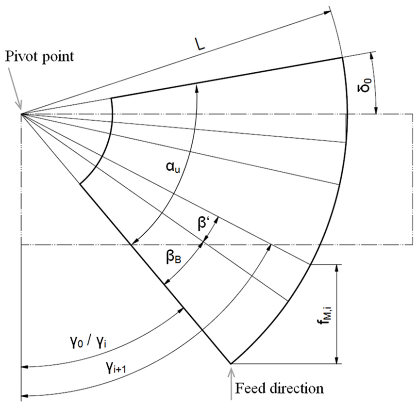
Sketch for the calculation of the linear feed.
The initial angle of the blank γ
0
can be determined from the measurable angle of the blank in the machine with respect to the lower beam δ
0
, the opening angle of the cone unfolding α
u
and the relative position to the machine. Each further angular position γ
i
is calculated from
This trigonometrical calculation modifies the feed in a way that ensures constantly fed angular segments.
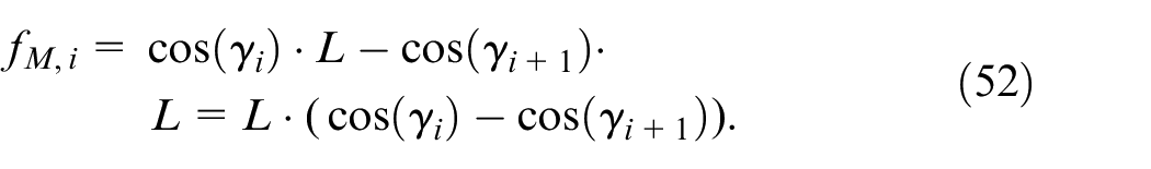
The practical bending tests were performed based on the validation cones A–D. The developed shape for each cone was cut from 3 mm thick S235JR sheet metal, see Figure 21(a). The kinematic parameters as given by the analytical process model were derived for the validation geometries, as presented in Table 2, and accordingly set at the machine. The bending machine then operated in a sequential procedure according to the desired number of corners n′, cf. Figure 21(b).
Experimental process for the incremental bending of cones on a swivel bending machine: (a) blank cut to the cone’s developed profile, (b) incremental bending process and (c) result from a practical bending test (here: geometry B).
Open shells of truncated cones formed from sheet metal were obtained from the bending experiments as shown in Figure 21(c) and subjected to geometric evaluation by touch probing.
Results
The geometries, resulting from the numerically calculated incremental bending process, were obtained as deformed mesh consisting of shell elements. Figure 19(b) shows the deformation result after spring-back for validation geometry B. From this computer-generated result, the radii of the truncated cones were measured at their tops and bases (r, R respectively) by circular interpolation of three FEM nodes. In addition, the opening angles at the open shells’ tops and bases were obtained as geometric results from the simulations. The cone angle,
From the physical bending experiments on the swivel bending machine, sheet metal cones were formed by using the process parameters calculated in Table 2. Because the feeding unit (back gauge) pushed the blank at the furthermost edge, an initial angle needed to be present, so the blanks edge could slide transversally within the feeding unit while pivoting about the angular feeding constraint.
1
Hence, a reduced number of bending increments was employed during the experiments (geometry A: n′ = 7; B: n′ = 6; C: n′ = 17; D: n′ = 6). The geometries resulting from the practical experiments, shown for example in Figure 21(c), were evaluated using a touch probe, type
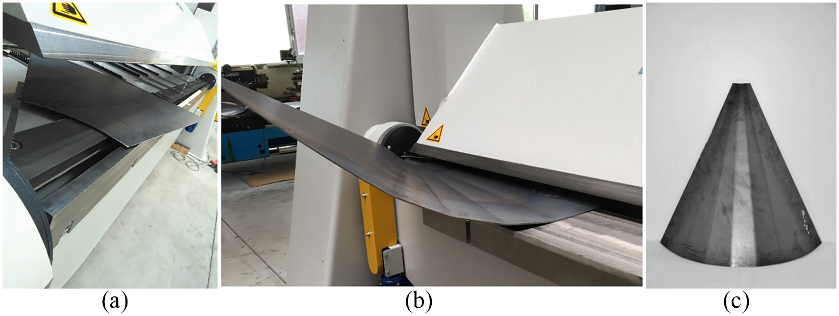
The analytical process model of section 2.2 has been used for the estimation of the kinematic parameters for the experimental and numerical approaches. For objective comparison, these parameters were applied to the simulations and the practical experiments without any iterative compensation. At this point, it must be emphasised, that purely analytic modelling by means of independent mathematical calculations is an aspirational approach, as minor modelling deviations in an incremental bending step are likely to accumulate throughout the process sequence. Influences which are difficult to model, but which still might be tolerated in a production, such as machine stiffness or clearances, could severely influence the results obtained from an idealized model and a corresponding incremental process of numerous sequences. The results from the FE-simulations as well as the averaged geometrical values from the physical experiments are summarized in Table 3 and set in relation to the target geometries. Figure 22 provides the corresponding qualitative diagrams of the results.
Results from finite element simulations and experiments for incremental manufacturing of conical geometries (A–D) on a swivel bending machine. The results of both methods are set in relation to the geometric parameters of the target geometries. Indirectly measured or extrapolated results are listed in parentheses.
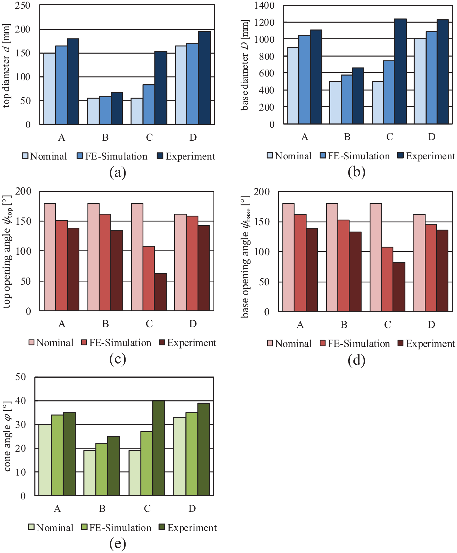
Qualitative comparison of the geometric dimensions of the target values and numerical and experimental results when utilising kinematic process parameters as dimensioned by the analytics of section 2.2.
The diameters of the simulated cones are on average 10% larger than the target values predicted by the analytical model. As a consequence, the opening angles ψ of the simulated parts are smaller, than desired, because the developed profile of each cone’s blank has been specifically related to the diameters and opening angle of the respective target geometry. Concentricity of the cones can be rated by the difference between both opening angles. In the case of the simulations, differences between ψtop and ψbase were observed but without a general trend considering all geometries. Also, the measured cone angles,
The geometrical trends observed in the simulated validations were confirmed by the experiments, which, in all cases, also resulted in larger cones. The coarse geometries (i.e. a limited number of corners n′) A, B and D revealed on average 23% larger diameters than the target geometries. Geometry C was manufactured with a threefold increased number of corners to achieve a smoother resulting cone. However, the process parameters, as defined by the calculations and conducted in the experiments of C, delivered significantly increased diameters in comparison to the target geometry. Naturally, due to the larger diameters, the cones from the bending experiments have smaller opening angles ψ. As indicated by the difference of top and base opening angles, reasonable concentricity was achieved in the bending experiments A, B and D.
Besides the geometric parameters of the bent cones, the distribution of bending radius was evaluated along the arc length at the truncated cones’ top and base radii. With the help of the above mentioned CMM, line sweeps were carried out along the bent reference geometries edges. These sweeps were then transformed into curvature distributions according to the procedure described by Vatter and Plettke. 28 For the experimentally manufactured truncated cones B–D, the resulting radius over arc length plots at the tops and bases are illustrated in Figure 23.
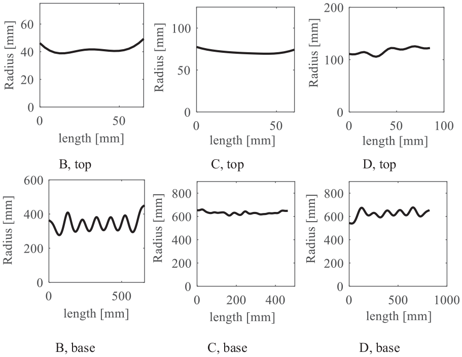
Constant trends of bending radius over arc length are evaluated at the incrementally manufactured open truncated cones’ tops and bases from edge to edge. Depending on the angularity of each respective geometry, a superposition of a periodical oscillation results from the bent edges.
The trends of radius distribution over arc length at the cones’ top and base edges show nearly constant trends in average, even if a periodical oscillation is superposed on the resulting trend. The oscillation is associated with the bent corners. In the case of the truncated cone A, radius over arc length is not considered in the context to evaluate the cones’ skewing because constant segments have only been bent in a partial area of this specimen.
Discussion and outlook
The model developed in section 2.2 provides a strictly analytic approach in order to relate the geometric parameters of open truncated cones to the process parameters necessary for manufacturing. The model is based on a repeated, incremental sequence carried out on a swivel bending machine. Within the incremental sequence, the bending step involves the use of an inclined upper beam to allow for the differing diameters at the top and the base of the cone. Throughout the manufacturing process, bending is alternated with feeding steps in n′ sequences. Radial feeding is supposed to feed the blank by constant angles β concentrically to the radii of the developed blank shape of the truncated cone. According to this process, experiments were conducted based on finite element simulations and practical bending tests on a swivel bending machine. Both methodological approaches were parameterized according to the developed analytical process model and produced different truncated cones similar to the target geometries with, in general, larger diameters than predicted by the process model.
An important aspect, which contributed to the observed deviations, is the initial lifting of the blank before full contact was established and before any deformation took place. The associated dead angle ξ that the bending beam rotates must be taken into account when determining the bending angle α which, hence, must be larger than the loaded bending angle λ l resulting from plasto-mechanic calculations. ξ is determined by the heights of the upper beam hd, hD, blank sheet thickness s and the assumed locations of contact between blank and tools after the bending beam passes ξ. Because of the gap between the upper and lower beams, the blank will freely move during the initial pivoting of the bending beam. Contact at the surface of the bending beam will occur depending on the conical geometry of the previous incremental bending process and the previously fed angular segment β b .
The analytic model assumes constant curvature throughout an incrementally bent arc, cf. Figure 8. However, because swivel bending represents a three-point bending technique, the maximum moment is induced at the contact point with the upper beam decreasing towards the contact points with the bending beam and lower beam. Though the model assumes a constant curvature between these three contacts, for various bending techniques curvature-steady trends have been identified for the bent corners entry and exit areas.29–31
In the analytic approach as presented, it is assumed, that the blank is lifted parallel to the machine without tilting (cf. Figure 15). If tilting were to be considered, it is questionable, where the rearward point of contact needs to be assumed because it would depend on the machine’s geometry and/or the remaining straight part of the blank. The location of contact would, even more, depend on any vertical constraint provided by the back gauge and the resulting elastic deflection of the straight part of the blank at the back of the machine. The simplifications assumed in the analytic modelling of the initial bending angle ξ would also gain importance, if smaller angles have to be bent, so that the proportion of initial lifting movement without blank deformation becomes a larger part of the total bending angle α. This can be seen clearly in the case of the resulting deviations of validation geometry C, which was bent with three times the number of sequences compared with geometry B. The finite element model was also influenced by constraints applied to the rearward edge of the blank to achieve an angular blank feeding. The simulation thus also represents a simplification of real experiments, even if it is possible to calculate the blank’s tilting and deflection at each respective sequence. The observed deviations of both, analytical and numerical models neglect the influence of gravity and machine stiffness.
Concluding, the method using an inclined upper beam for swivel bending of conical geometries from sheet metal in a sequential process delivered reasonable results, even if a very large number of increments was applied to achieve the manufacture of smooth cones, see Figure 24.
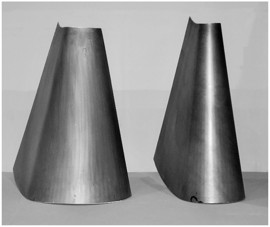
Smooth cones bent in an empirical experimental process on a CNC folding machine with inclined upper beam and circular feed. 17 .
The strictly analytical model presented here can be considered as advantageous for manufacturing truncated cones with coarse angularity. However, modelling the initial bending angle ξ in an accurate way is challenging due to the reasons raised in the paragraphs above which are related to the gap below the upper beam. Especially when bending smooth conical geometries, accumulation of modelling errors leads to less accuracy when the number of incremental steps is increased. To achieve higher accuracy, corrections are necessary, for example, by empirical experiments. A more sophisticated approach could be the potential implementation of a grey box methodology, which has been successfully applied to diverse bending problems, for example, Pettersson et al. 32 and Vorkov et al. 33 On the other hand, a process variation with a closed upper beam during the bending step could lead to more distinct boundary conditions and the process could be modelled without the problems regarding the initial blank lifting.
Concentricity is represented by the variation between the opening angle at the top, ψtop, and the base ψbase of the truncated conical half shells. As exhibited by the practical bending experiments, reasonable concentricity was achieved by the proposed methods, mainly associated with the inclination of the upper beam. The inclination results in different loading radii at the top and base of the truncated cone. Without inclination, in contrast, too wide radii would result at the top while too narrow loaded radii would occur at the base. As a consequence, when considering the arc length given by the unfolded edges of the truncated cone, incorrect loading radii also lead to incorrect opening angles. Thus, non-concentric geometries would emerge because of the resulting variation of opening angles between top and base. Preceding this paper, cones were bent in initial tests by the method described in subsection 1.2. While these preliminary tests have revealed on average 22 degrees narrower opening angles at the base of truncated cones than the top, cf. Figure 3(a), the deviation could be improved to 3° on average over the practical bending experiments of the present study, that is, A, B and D. Experiment C is considered invalid in this context because the high overall geometric deviation between target geometry and experimental result. This deviation partially relates to the mismatching blank shape, which is developed according to the target shape of the truncated cone geometry C, even if much larger diameters were obtained from the respective bending experiment.
Skewed profiles have been observed when bending using ‘the state of the art’ process for incremental bending of cones on a swivel bending machine. Skewing is associated with a clear inclination of the trend in the distribution of bending radius plotted over the arc length at the top and base diameter of an open, truncated cone, see Figure 3(b). With a standard back gauge on a swivel bending machine, blanks are fed linearly. For the incremental bending of conical geometries, this motion must be converted to an angular feed. In this study, a transformation is suggested to achieve constantly fed angular segments instead of constant linear feeding distances intended to prevent the profiles’ skewing. By the modified feeding procedure, this production defect could be limited sufficiently based on the results of three individual geometries. In practice, the swivel bending machines are now provided by the manufacturer with a back gauge with two independent linear drives, which can be programmed to produce the desired rotational movement. Using this back gauge, it is possible to feed directly the segment angle β B in between two bending increments without need of the trigonometrical transformation of equation (52). The presented analytic model thus unrestrictedly applies even if a radial feeding unit is operated at the swivel bending machine.
Conclusion
Compared with other common manufacturing techniques, such as deep drawing, spinning, rolling or air bending, conical sheet metal profiles can be manufactured in a sequential process on swivel bending machines. Due to the inherent flexibility provided by the kinematic forming method, the manufacture of cones on a swivel bending machine offers advantages in terms of the range of geometrical product variations that can be produced. Furthermore, on the same machine, products can be manufactured with conical profiles in combination with other geometrical features such as sharp bends. So far, however, no models for determining the processing parameters for conical geometries were available for the incremental operation of this bending method. Up to now, swivel bending of truncated cones has only been applied by trial and error approaches, using operator experience to establish the forming parameters for a particular geometry.
With the ‘state of the art’ incremental operation of a swivel bending machine, characteristic bending defects have been identified when manufacturing conical shapes. The opening angles of an open truncated conical shell differ significantly from top to base because the top is bent too wide whilst the base features a too narrow diameter. This also results in a non-concentric misalignment of the diameters at the top and the base of a truncated cone. Skewed profiles result because within each sequence of the incremental process, the back gauge on the machines feeds the blank by constant linear distances between each respective bending step.
In this paper, an analytical process model is derived that
Takes into account the alternating sequence of bending and feeding,
Calculates spring-back within each bending step,
Delivers the required process parameters for the swivel bending machine.
In order to take the variation of radius from the conical geometry’s top to base into account, the bending beam is set in an inclined position and height above the lower beam, so that variable three-point-bending conditions are achieved over the full width. In addition, a trigonometric transformation from the linear back gauge to uniform fed arc segments in between bending steps is proposed.
For critical validation purposes, the process model has been applied to four truncated conical geometries and the corresponding process parameters were calculated. A finite element simulation model was established based on rigid tool surfaces and square shell elements to numerically calculate the resulting geometries from these process parameters. For practical bending experiments, a swivel bending machine was equipped in a way to achieve the desired process modifications with regard to an inclined upper beam as well as to feed constant arc segments in between bends. Blank shapes were cut in accordance with the developed profile of the cones and bent with the process parameters derived by the analytic process model.
From the evaluations of both methodical validations, the following conclusions are drawn in the context of this study:
The analytic model is designed to determine the kinematic process parameters for the sequential production of four distinct truncated cones on swivel bending machines. In the case of coarse segmentations (a corner every 15°), deviations in diameter between the model and the results of practical bending experiments of the order of 23% were observed. If the number of corners is significantly increased to produce smoother conical shapes (a corner every 5°), the process model loses accuracy because the initial lifting of the blank influences the process severely. Therefore, semi empirical extensions of the analytics, for example, a grey box approach, are suggested. On the other hand, a process variation with a closed upper beam could provide more defined geometric premises for modelling.
Due to the incremental mode of operation and the relationship of the very small edge radius of the upper beam compared to the blank’s large surface, numerical calculations are extensive. Trial and error approaches based on the suggested simulation model are hence time consuming. Therefore, initial kinematic process parameters using the analytical model were utilised in the present study. When comparing the numerical model to the practical bending experiments, similar conical geometries were obtained. Compared to the simulations, larger diameters resulted in the practical experiments, which is mainly presumed to relate to the loose boundary conditions of the open upper beam and unclamped feeding attachment. In addition, for performance reasons, the simulation model does not take the machine’s rigidity and gravitational influence on the blank into account.
For conical geometries, the suggested process changes of swivel bending have clearly improved the geometric defects associated with the ‘state of the art’ method. During forming, the tool inclination is intended to produce a difference in the loaded radius at the base and the top of the truncated cone, respectively. Hereby improvements in the manufactured top and base diameters concentricity as well as more even opening angles at top and base were achieved in the presented bending experiments. In addition, skewing has been observed in the initial conical profiles. The defect can be assessed by means of the trend of bending radius over arc length at the top or base edge of the open truncated cone. This distribution is supposed to be constant for an ideal conical geometry. Within this study, it is proposed to feed in uniform angular segments in between the bending steps to avoid skewing, hence to homogenise the trend of radius over arc length. In the results, skewing could be suppressed sufficiently by the modified feeding method and evenly bent truncated cones were produced in the practical bending experiments.
Footnotes
Appendix
Authors’ Note
This paper has been written as a joint collaboration between the Chair of Forming Technology at the University of Siegen and Dr. Hochstrate Maschinenbau Umformtechnologien GmbH.
Declaration of conflicting interests
The author(s) declared no potential conflicts of interest with respect to the research, authorship, and/or publication of this article.
Funding
The author(s) disclosed receipt of the following financial support for the research, authorship, and/or publication of this article: The project has been financed by the