
Abstract
This article presents a method of design, manufacturing, and measuring S-gear. S-gear is a kind of gear whose tooth profile is an S-shaped curve. The sine (cosine) gear, cycloid gear, polynomial gear, and circular arc gear are all S-gears in essence. In the S-gear transmission, the concave surface of one gear and the convex surface of the other gear contact each other. Therefore, the power transmitted by S-gear is much larger than that of the convex-convex-contact involute gear. Some scholars have studied the characteristics of S-gear, but few have explored its manufacturing. In this article, the Numerical Control (NC) machining technology of S-gear is studied in detail for its industrial application. The polynomial curve is used to construct the tooth profile of the S-gear based on the Gear Meshing Theory. The mathematical model of polynomial S-gear is established, by which involute gear can be represented as a special S-gear. The steps of generating NC codes are described. Then, the S-gear sample is processed with an NC machining center. Finally, the sample is measured with a Coordinate Measuring Machine (CMM), and the measurement results show that the accuracy of the S-gear processed by the NC machining center reaches ISO6. This research provides a feasible approach for the design, manufacturing, and measuring of S-gear.
Introduction
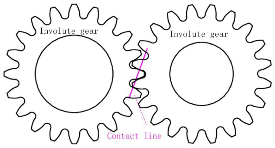
The tooth profiles of cylindrical gears are composed of curves. Different curves construct different types of gears. Their common characteristic is that they can transmit motion continuously and smoothly. In the 18th century, gear transmission began to be widely used. Cycloidal gears were first developed, then involute gears. Until the beginning of the 20th century, involute gears have been dominant in industrial applications. This is due to the following advantages of involute gears: (1) constant transmission ratio, (2) constant direction of positive pressure, (3) simple processing. Involute gear has been standardized, and its processing technology is mature.
Although involute gears have been widely used, the researches on non-involute gears have never stopped, such as cycloidal gears, sine (cosine) gears, circular arc gears, and so on. Koide et al. 1 tested the tooth surface temperature and the power transmission efficiency of plastic sine-curve gears in the running condition. Test results showed that the sine-curve gears for the operating condition had lower tooth surface temperatures and higher power transmission efficiencies than involute gears. Wang et al. 2 described the generation principle of a cosine gear and established the mathematical models based on the meshing theory. Researches showed that the cosine gear drive has lower sliding coefficients, and the contact and bending stresses of the cosine gear are reduced in comparison with the involute gear.3,4 Wang et al. 5 proposed an internal gear with a given circular arc path of contact. This internal gear has a much higher contact ratio, and its bearing capacity is greatly improved compared with the traditional involute internal gear. Bair 6 and Chen and Tsay 7 studied the tooth profiles of circular-arc elliptical gears, which have a convex-concave tooth profile contact. Zhang et al. 8 and Chen and Wang 9 investigated the characteristics of double circular-arc helical gear by computerized simulation of meshing, but they did not manufacture gear samples and did not carry out experimental verification. Fujiwara 10 invented a gear with a few teeth whose tooth profile is made up of partial cycloids. Compared with involute gears, it has a better tooth height advantage, but it has not been tested and applied.
S-gears have several advantages over involute gears due to the convex-concave-contact between the contact teeth (see Figure 1). The convex-concave-contact leads to lower contact stress, less sliding friction, and less heat generated. 11 Zorko et al. 12 established a model for the evaluation of the root and flank load-carrying capacity of polymer S-gears. Zorko pointed out that there is a need for an additional factor that would cover the influence of geometric deviations on the stress and temperature state of the S-gears.
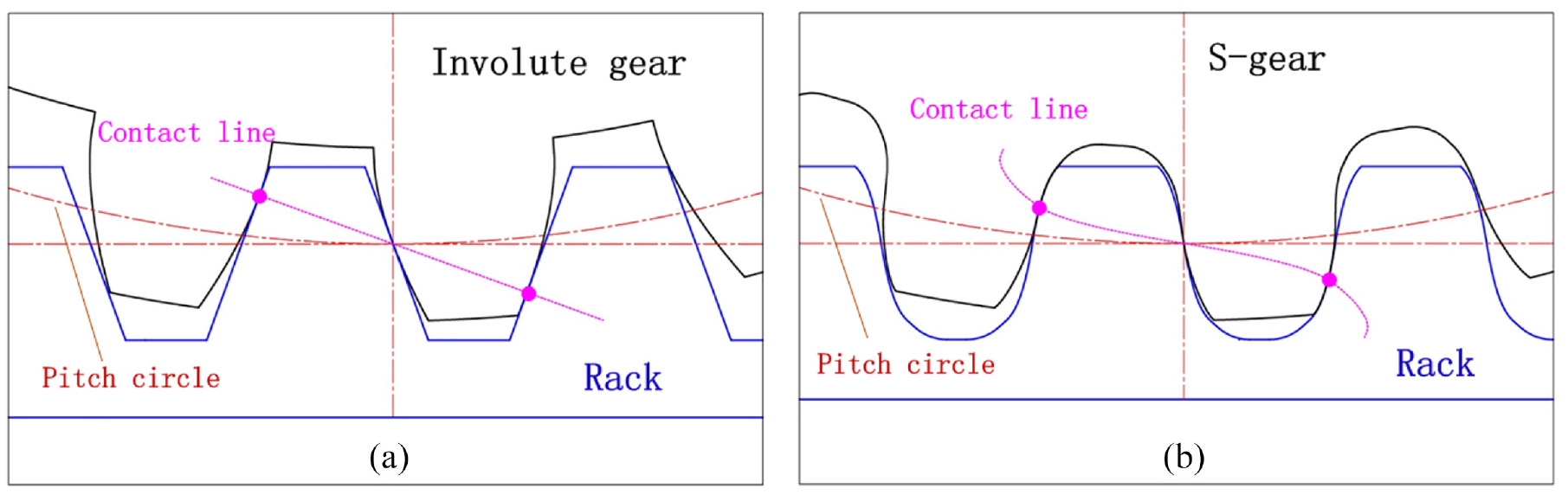
Gear and rack teeth: (a) involute with convex-convex contact and (b) S-gear with concave-convex contact.
In recent years, using general NC machining equipment instated of special equipment to produce gears has become a feasible way of gear manufacturing, especially in single pieces or small batch production. Li et al. 13 introduced a new spur gear shaping method, which enhances process efficiency by optimizing the circular feed rate. Ding et al. 14 established the NC milling model for machining spiral bevel gear. Ding pointed out that the gears processed by the universal NC machining center can achieve high precision, and the milling method is of great importance for the actual process to the small batch, large modulus, and large size gear. Chiang et al. 15 proposed a simplified pseudo-planar gear cutting simulation method using ObjectARX in an AutoCAD environment. Hsu et al. 16 proposed a new shaving method for double-crowning that has no natural twist in the tooth flanks on the work gear surfaces which used a variable pressure angle shaving cutter in a parallel gear shaving process. Wei et al. 17 proposed a method to improve processing accuracy and efficiency of tooth crest chamfering of spiral bevel gear using ball end milling cutter. Khaghani and Cheng 18 presented an approach to tool path generation for ultraprecision machining of freeform optic surfaces. Wang et al. 19 proposed a milling method for a spur face gear using a five-axis NC milling machine. This study demonstrated that the generating milling method could be applied in precision milling of the spur face gear. However, It is not a general gear milling method, because a special 5-axis milling machine is developed and used.
In this article, the NC machining technology of S-gear is studied from three aspects of design, manufacturing, and verification. The main contents include the mathematical model of S-gear, NC machining codes generation, self-developed CAM software, simulation of NC machining, manufacturing, and automatic measuring with CMM.
Mathematical model and characteristics of polynomial S-gear
Mathematical model of polynomial S-gear
Rack profile
Polynomial S-gear is a form of S-gear. In mathematics, polynomial refers to the expression obtained by variables, coefficients, and their operations of addition, subtraction, multiplication, and power (non-negative integer power). The polynomial function can be expressed as y = a0 + a1x1 + a2x2 +…+ anxn. The tooth profile of polynomial S-gear is a part of the polynomial curve. Take the quadratic polynomial as an example to explain the construction process of the rack profile. The basic shape of the quadratic polynomial function is shown in Figure 2.
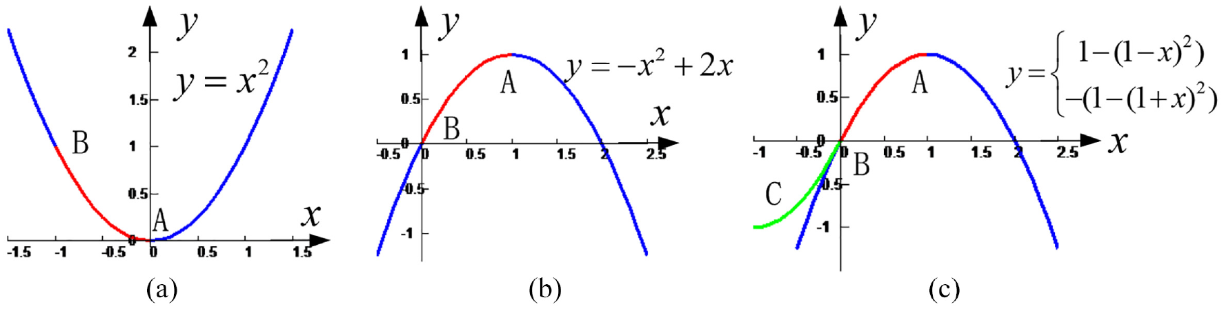
Curves of quadratic polynomial functions: (a) basic curve (b) transformed curve, and (c) S-gear curve.
Figure 2(b) is obtained from the curve in Figure 2(a) after translation and rotation. The curve ABC in Figure 2(c) can be used as the basic profile of S-gear rack. Figure 3 shows the relationship between the rack profile and the polynomial curve.
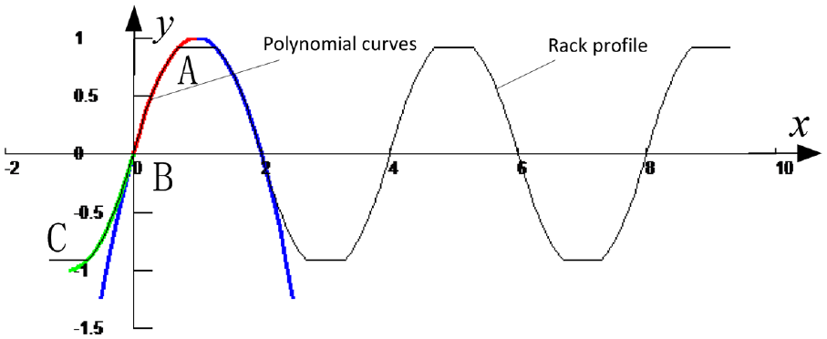
Rack profile of polynomial S-gear.
The quadratic polynomial function can be expressed as y = a2x2 + a1x + a0. x is an independent variable; y is the variable that represents the curves; a2, a1, a0 are constant real numbers. As shown in Figure 2(b), at point B, x = 0, y = 0; at point A, x = 1, y = 1 and x = 1, y′ = 0. The equations are as follows:

So the quadratic polynomial curve AB is presented as follows:

Similarly, the teeth profiles of cubic polynomial and quadric polynomial S-gears can be obtained as follows:


Formulas (1)–(3) can be uniformly represented as follows:

In Figure 3, the curve ABC, which consists of curve AB and BC, represents a complete tooth profile. The two curves AB and BC can be expressed in a unified way:
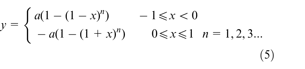
In Formula (5), both coefficient a and exponent n can control the shape of the tooth profile, and exponent n also indicates the order of the tooth profile. Formula (5) can represent the basic tooth profile of any polynomial S-gear.
Generation of tooth profile
Formula (5) can represent the rack profile. Through the gear meshing theory, the equation of the S-gear tooth profile can be obtained. The steps are as follows (see Figure 4):
Firstly, the basic tooth profile is constructed, and the basic tooth profile is used as the rack tooth profile.
Then, the gear profile is obtained by enveloping the rack profile (see Figure 5).
S-gear meshing theory.
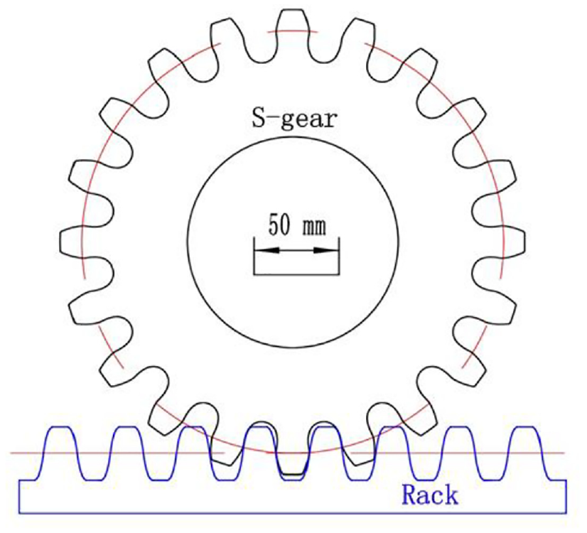
Rack and S-gear with modulus 12.5 and teeth 20.
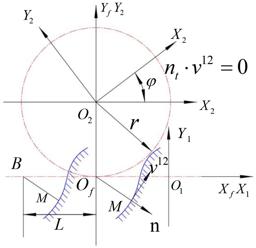
As shown in Figure 4, the coordinate system Sf (Of, Xf, Yf) is a fixed coordinate system, and the coordinate system S1 (O1, X1, Y1) is a moving coordinate system. The moving direction is along X1. t represents the time, t0 is the initial time, t1 represents a certain time after the initial time. At t = t0, the coordinate system S1 coincides with the coordinate system Sf. The coordinate system S2 (O2, X2, Y2) is a rotating coordinate system. At t = t0, the origin of the coordinate system S2 is located at the point (0, r) of the coordinate system Sf. After a period of time, at t = t1, coordinate system S1 moves L along X1, coordinate system S2 rotates ϕ around O2.
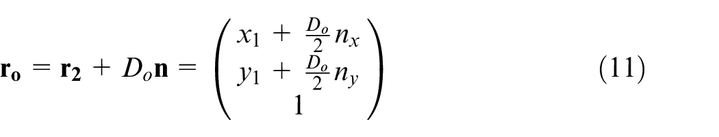
The vector


Where
The rack is fixed in the coordinate system S1. M is a point on the rack profile (see Figure 4). According to gear meshing theory, when point M becomes the meshing point, the relative velocity and the normal vector at point M must be perpendicular to each other, that is, the product of the relative velocity and the normal vector must be 0.

At t0, the intersection point of normal vector
In the coordinate system S1, the point M on the tooth profile of S-gear is expressed as a third-order vector:
Write the vector
Where
Figure 5 shows rack and gear with order 5, modulus 12.5 and teeth 20, which are derived from Formula (9) and Formula (10), respectively. According to Camus theory, a pair of rack cutters that can overlap each other on the tooth profile can machine conjugate gears.20–22 Because the two curves of the rack are consistent, the S-gears with the different number of teeth constructed by the same rack can mesh with each other.
Relation between polynomial S-gear and involute gear
In Formula (5), both coefficient a and exponent n can affect the shape of the tooth profile. Coefficient a affects the pressure angle. The larger the coefficient a is, the smaller the pressure angle is. Exponent n affects the curvature of the gear profile. The larger the exponent n is, the greater the curvature of the tooth profile is (see Figure 6). Figure 7 shows the difference between S-gears with exponent n = 2 and n = 5.
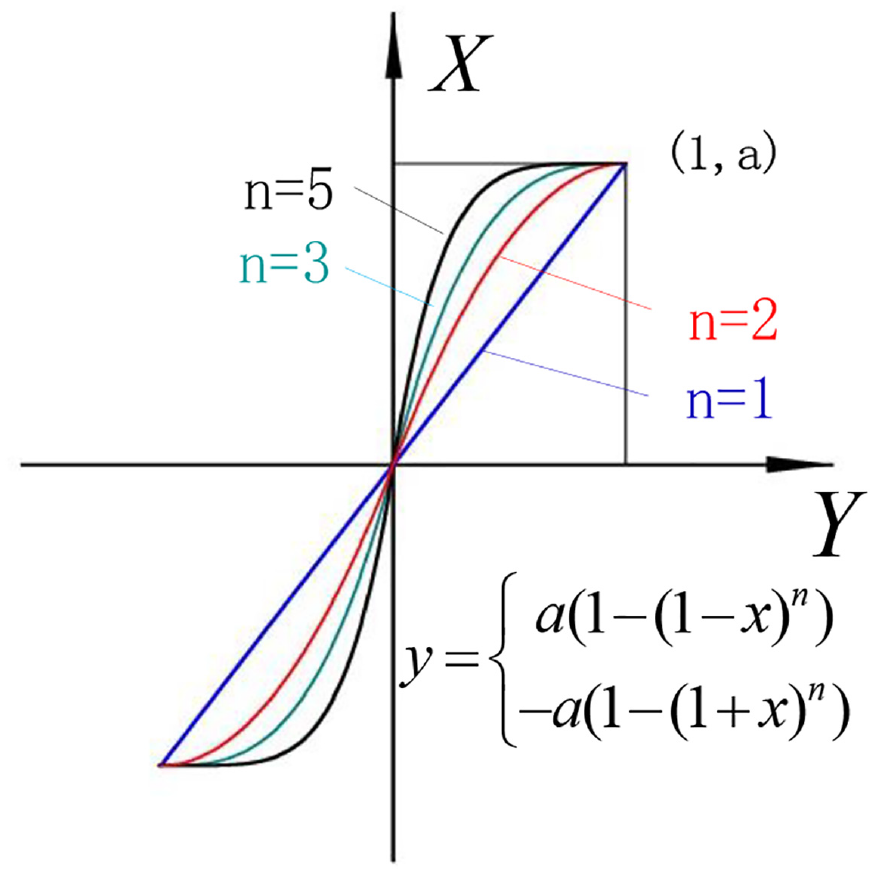
Basic profile of S-gear with order n = 1, 2, 3, 5.
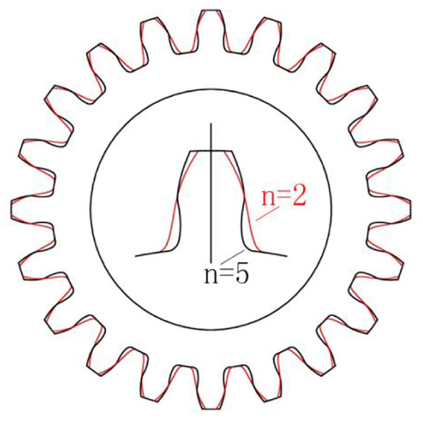
S-gear with n = 2 and n = 5.
When n = 1, the rack profile becomes a straight line, the meshing line becomes a straight line, and the gear becomes an involute gear. Therefore, involute gear is a special kind of polynomial gear. In particular, when a = 2.7475, n = 1, the gear becomes a standard involute gear with a pressure angle α = 20° (see Figure 8).
Involute gear with a = 2.7475 and n = 1.
Characteristics of polynomial S-gear
In this section, the characteristics of S-gear will be discussed compared with involute gear. Table 1 lists the characteristics of S-gears and involute gear, including contact ratios, synthetic radius of curvature and relative slip rates. S-gears and involute gear use the same number of teeth, modulus, tooth height coefficient and backlash. The exponent n of involute gear is n = 1 and the size factor a is 2.7475. The exponent of S-gear is n = 3, 5, 7, and the size factor a is 1.3.
Characteristics comparison of S-type gears and involute gear.
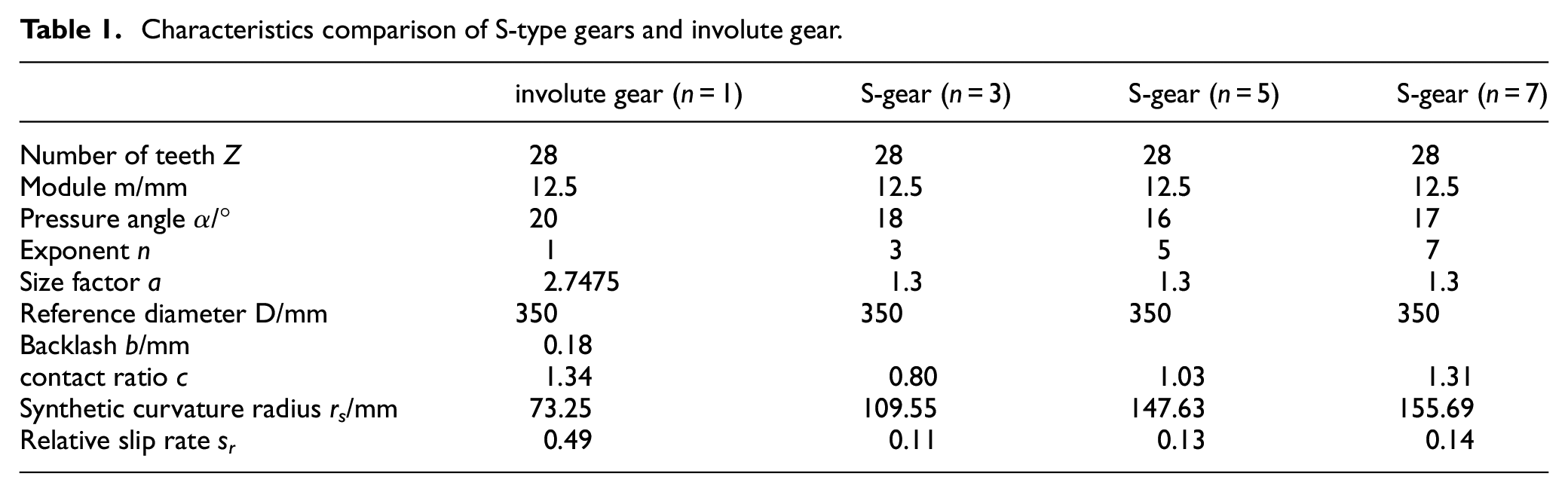
Figure 9 shows the values relative to the involute gear. It can be seen from the table that: (1) the contact ratio of S-gear is slightly smaller than that of involute gear; (2) the relative slip rate of S gear is much smaller than that of involute; (3) the synthetic curvature radius of S gear is larger than that of involute gear.
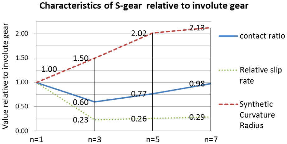
Characteristics of S-gears relative to involute gear.
As a result, S-gear has larger radius of curvature and smaller relative slip ratio, so it has larger bearing capacity and smaller wear.
NC machining for S-gear
NC machining equipment
NC machining center has various forms. They are vertical, horizontal and inclined according to their structure; three axes, four axes and five axes according to their motion axes; open-loop, semi-closed-loop and closed-loop according to machining accuracy. The vertical three-axis closed-loop NC machining center was chosen for S-gear manufacturing due to its high precision and low cost. In the process of machining, the position relations of NC machining center, milling cutter and workpiece are shown in Figure 10 as follows:
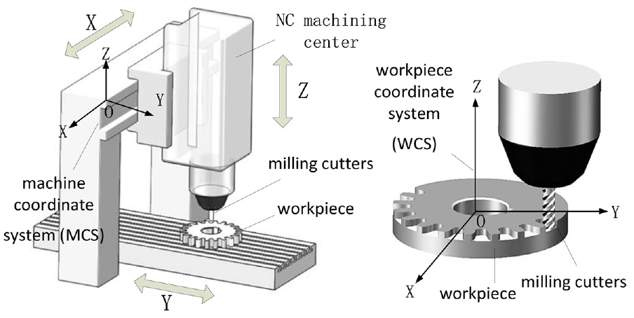
NC machining center, milling cutter and workpiece.
When using the NC machining center, the machine coordinate system (MCS) should be converted to the workpiece coordinate system (WCS) firstly. NC codes indicate the path of the cutter, which is established in the WCS. The origin of the WCS is located at the center of the workpiece (Figure 10). Under the control of NC codes, the three axes move along a specific path. Meanwhile, the high speed rotating cutter cuts the material of the workpiece. By setting appropriate cutting parameters, high speed and high precision machining can be achieved.
NC codes generation
Cutter path in NC machining
For cylindrical gears, there are two kinds of machining methods. One is layer by layer machining. The cross-section circle of the milling pin cutter moves along the gear profile curve. After finishing one layer, the milling cutter moves a distance to the workpiece and runs again according to the original path until the whole gear is machined (see Figure 11). The other is tooth-by-tooth machining. The milling cutter runs along the tooth profile of one tooth. After finishing one tooth, the cutter moves to another tooth until all the teeth are processed (see Figure 12). The first method is suitable for rough machining and the second method is suitable for finish machining. For both methods, the path of the cutter can be simplified to a plane path.
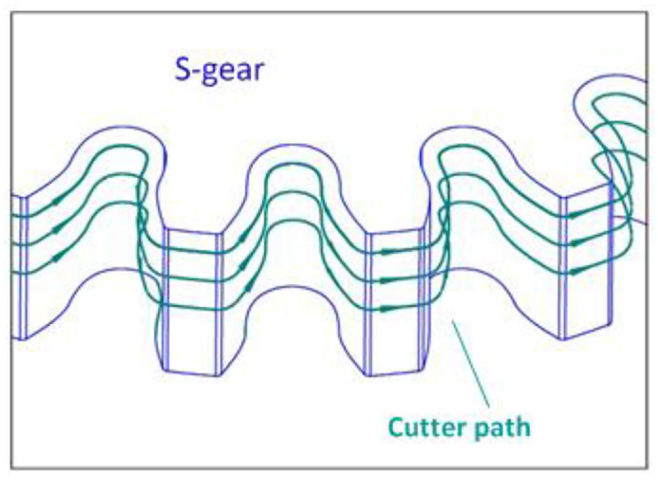
Cutter path for layer-by-layer processing.
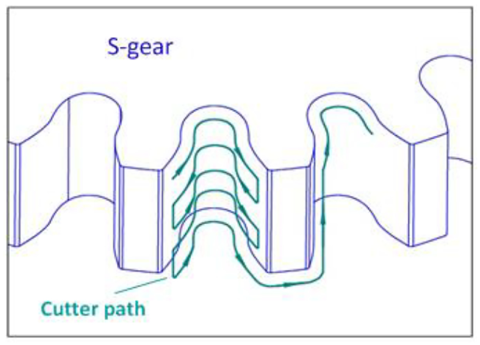
Cutter path for tooth-by-tooth processing.
Software for NC codes generation
The NC machining center runs according to the instructions of the NC codes. Three most essential parameters need to be specified in NC machining codes. They are spindle speed, cutter tip position and feed speed. In addition, it also needs to tell other auxiliary actions such as feeding, withdrawing and cutter changing. The calculation of the cutter tip position is the focus of the research. The cutter moves along a series of such positions, thus produce various shapes.
For cylindrical gears machining, the path of the cutter can be simplified to a plane path. The position of the cutter tip can also be determined by plane geometric relationship.
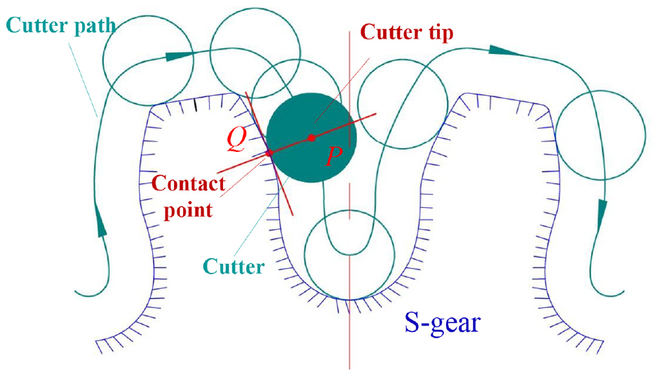
Geometric relationships between cutter and workpiece.
where,
Formula (11) expresses the calculation of the cutter tip position. To obtain the normal vector
The expression is as follows:
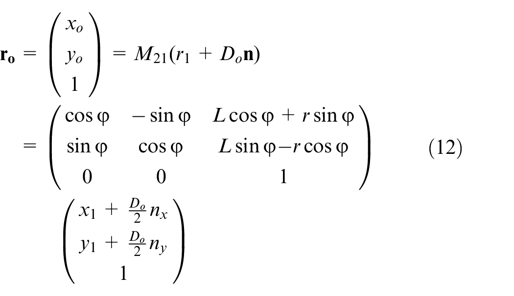
where
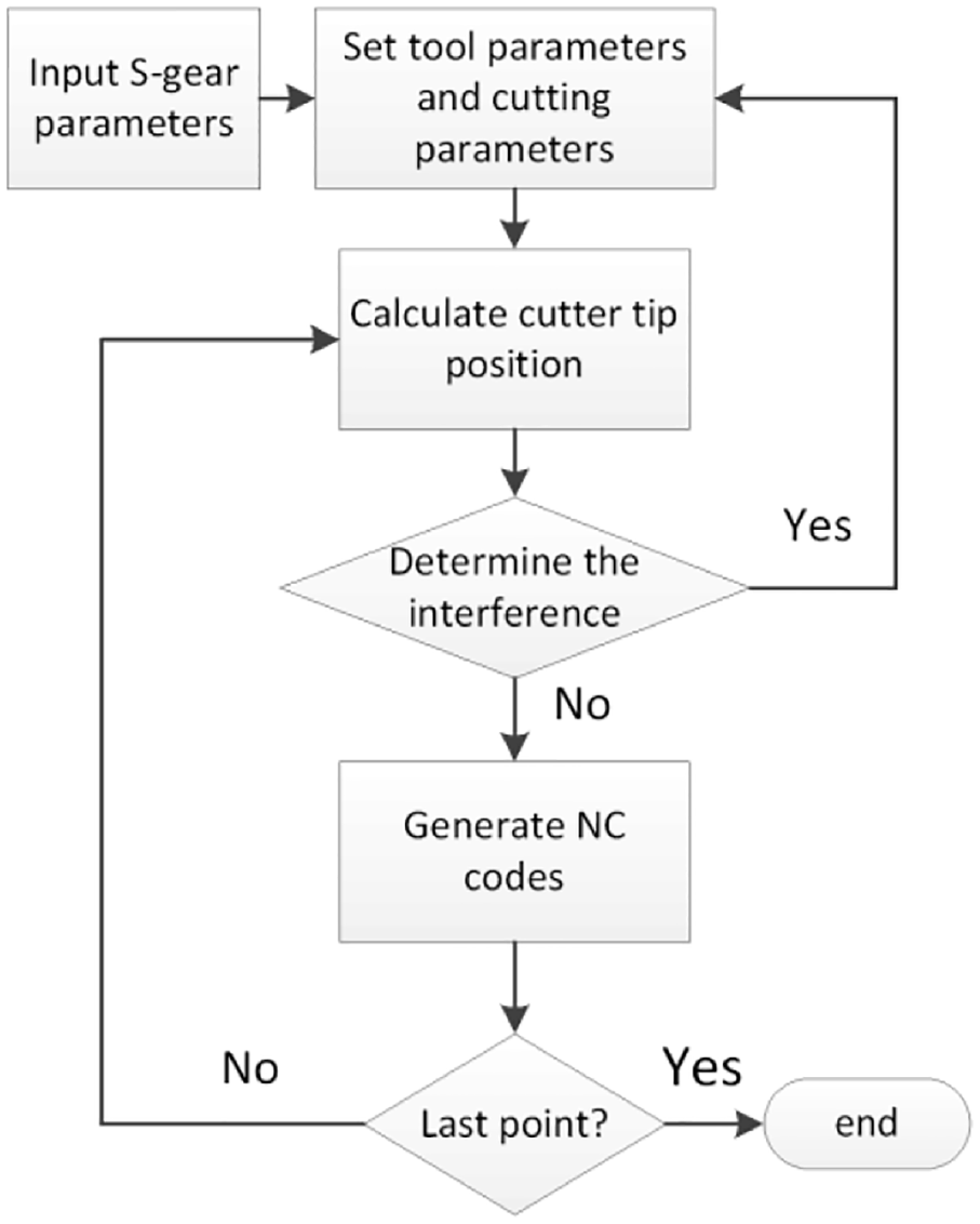
Formula (12) can be used to calculate the cutter tip position. According to the position of the cutter tip, the corresponding NC codes can be obtained. Software was written in C language to generate the NC codes automatically. The basic structure of the software is shown in Figure 14. Figure 15 shows a small piece of NC code generated by the self-developed CAM software.
Structure of code generate program.
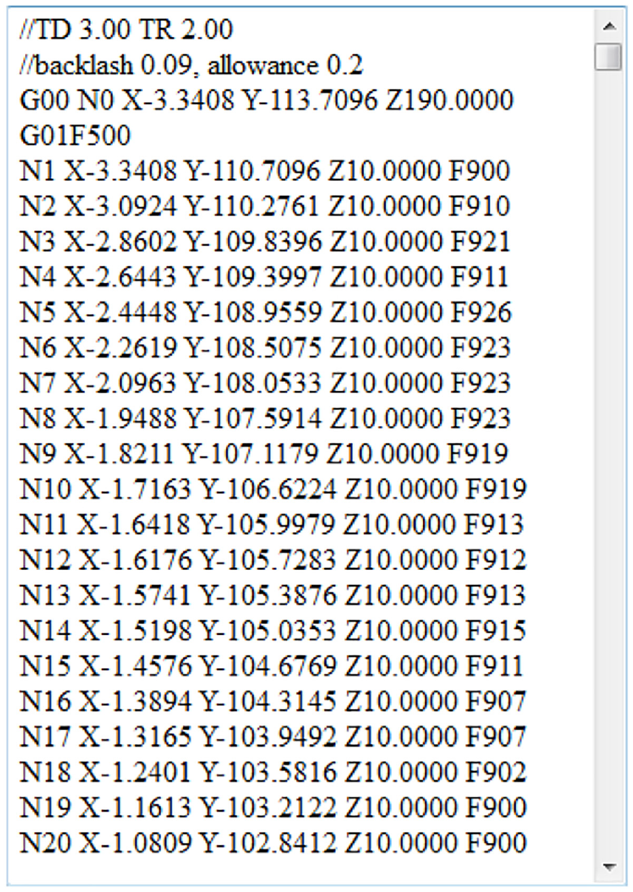
NC codes generated by self-developed CAM software.
NC machining simulation
The purpose of machining simulation is to verify the correctness of the NC codes, so as to avoid overcutting, undercutting and cutter bumping in advance. VERICUT 7.2 can be used to realize the simulation.
The simulation steps are: (1) establish the machine model and the workpiece model, (2) set cutters and number them, (3) load NC codes, (4) simulate, and (5) check simulation results. If the theoretical gear model is consistent with the simulation results, and there is no collision during the simulation, the codes are correct.
S-gear manufacturing
Parameters of S-gear
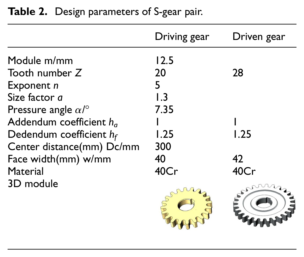
According to the conclusions of Sections 2 and 3, a pair of S-gears were designed and manufactured. Their modulus is 12.5 mm, and their teeth number is 20 and 28, respectively. Detailed parameters of the gears are shown in Table 2.
Design parameters of S-gear pair.
The material of gears is 40Cr. The main processes of material treatment were forging, annealing, tempering and quenching. The 3D models of the gears were established with SolidWorks 12.0.
NC machining
EXTRON M1600L was used for NC machining. EXTRON M1600L is a type of NC machining center, which adopts full closed-loop technology. The positioning accuracy is less than 0.015 mm/full length, and the repetitive positioning accuracy reaches 0.5
In order to improve the machining efficiency, gear roughing was completed in one time and gear finishing was completed in two times. There are 6 NC code files used in total. The machining time of driving gear is 180 min and that of driven gear is 245 min. Detailed cutting parameters are shown in Table 3.
Machining parameters of S-gear pair.
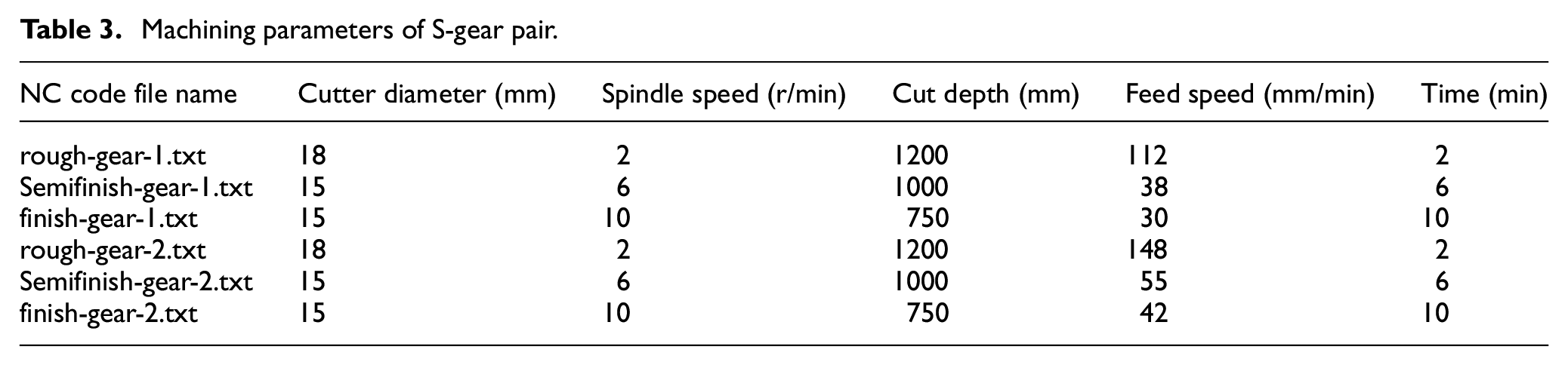
In this machining, high-speed steel end milling cutters were used for roughing and cemented carbide end milling cutters were used for finishing. From Table 3, it can be seen that 2 types of cutters were selected for this processing. Three factors, NC machining center, cutter and workpiece were considered to choose machining parameters. The optimized cutting parameters were obtained by trial cutting and adjustment.
With this machining method, the milling cutter extends longer (Figure 16(b)), and the cutting force may cause deformation of the spindle and the milling cutter. Cutter back-off and vibration may be generated due to the deformation, which may lead to tooth direction error. After finishing, the gear on the worktable should be measured by a dial gauge to ensure that the deviation of the tooth direction is within 0.015 mm (Figure 16(c)). Otherwise, finishing should be carried out again.
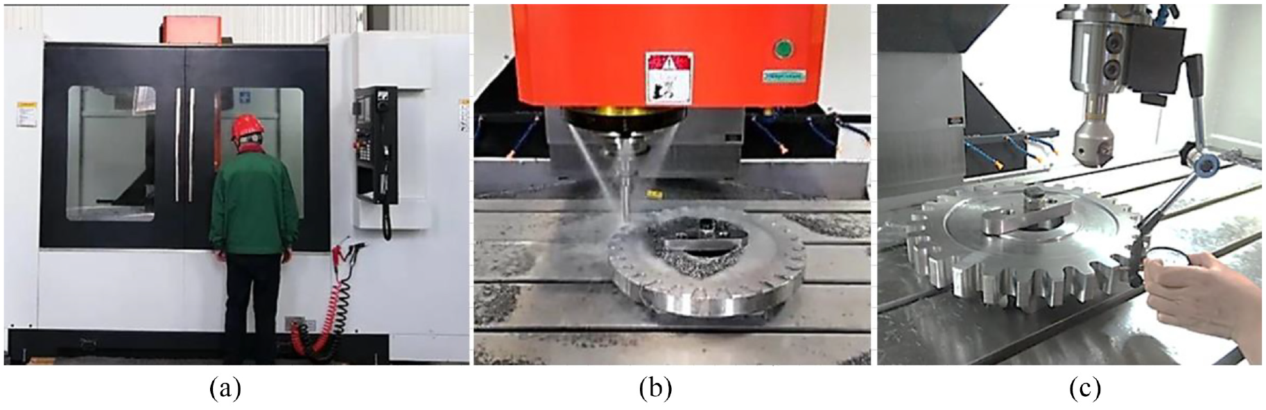
S-gear in machining: (a) NC machining center, (b) roughing, and (c) on-line measurement.
Prototype
Figure 17 shows S-gears produced with NC machining center. The tooth surface is smooth and glossy, which shows the good quality of the tooth surface. The dimensional accuracy of gears will be discussed in Section 5.
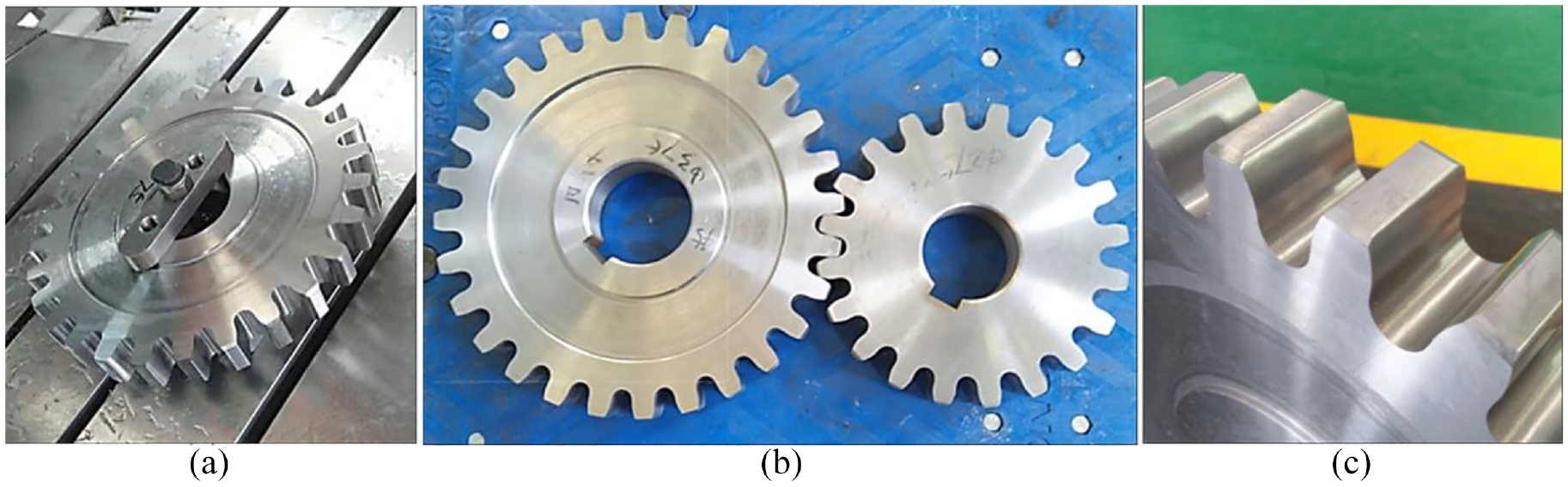
S-gear produced with NC machining center: (a) gear on worktable, (b) gear pair, and (c) gear tooth.
S-gear measurement
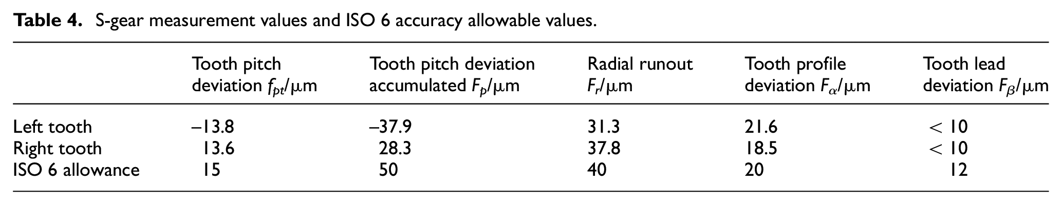
S-gear cannot be measured using the same measuring tools as involute gear. In this article, the CMM was used to measure S-gear, so as to evaluate the machining accuracy. The type of the CMM is Tornado NCA121510, its measurement accuracy is ±0.3 μm (see Figure 18). In order to show the accuracy of S-gear intuitively, the measured data were converted into the same measurement items as involute gear. They are tooth profile deviation Fα, tooth orientation deviation Fβ, tooth pitch deviation fpt, tooth pitch deviation accumulated Fp and radial runout Fr.23,24
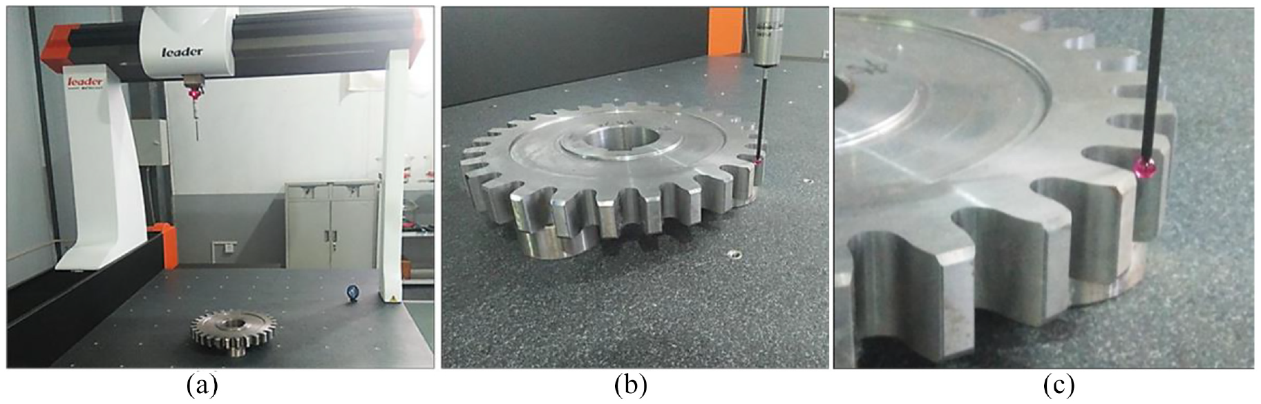
S-gear measurement: (a) CMM, (b) automatic gear measurement, and (c) probe and tooth.
Manual measurement is inefficient and low precision. In order to realize the automatic measurement, the Dimensional Measuring Interface Specification (DMIS) program was first developed, and then the MDIS program was used to control CMM for automatic measurement.
When measuring, the ambient temperature was 22–25°, the humidity was 10%, and the noise level was less than 10 decibels. The gear to be measured has 28 teeth in total. Number the teeth from 1 to 28. The horizontal axes of Figures 19 to 24 represent the numbers of the teeth. The measurement results are as follows:
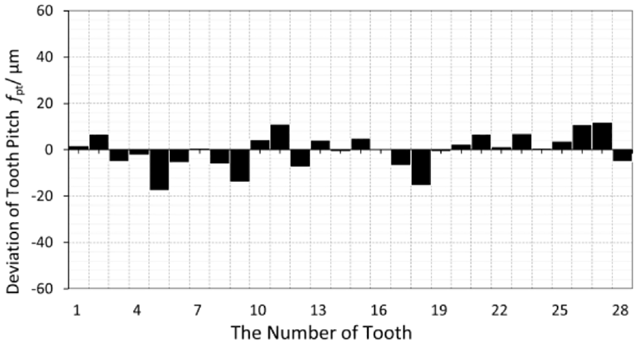
Pitch deviation of left tooth.
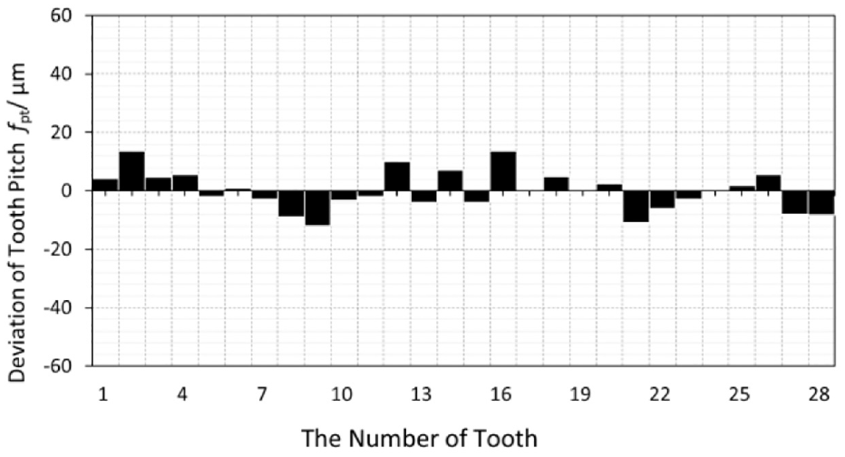
Pitch deviation of right tooth.
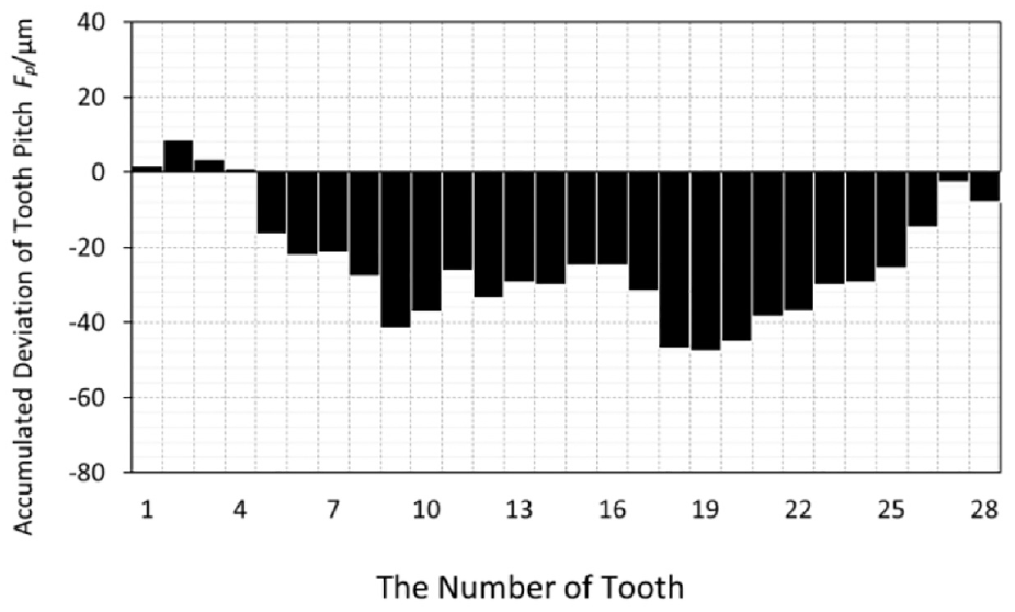
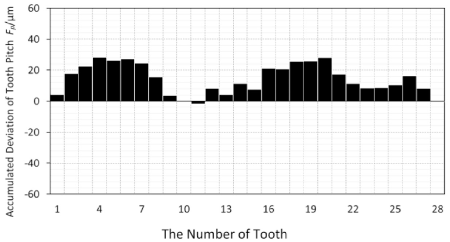
Pitch deviation accumulated of left tooth.
Pitch deviation accumulated of right tooth.
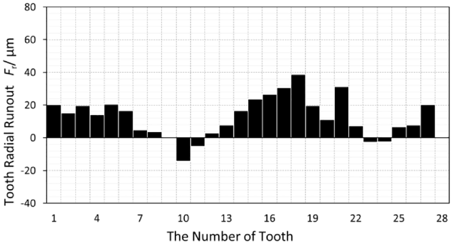
Radial runout of left tooth.
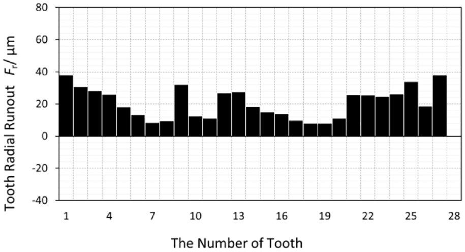
Radial runout of right tooth.
Figures 19 and 20 shows the measurement results of the deviation of the tooth pitch fpt The parameter fpt refers to the difference between the actual pitch and the theoretical pitch of the gear, which is an important index to ensure the stability and accuracy of the transmission. Figures 21 and 22 represents the accumulated deviation of the tooth pitch Fp. The accumulated deviations of the left teeth are almost positive; meanwhile the accumulated deviations of the right teeth are almost negative. This phenomenon is caused by deformation of the machine spindle and cutter under the action of cutting force, which deviates from the theoretical teeth surface. This kind of machining error can be reduced by adding compensation to the NC codes. Figures 23 and 24 represents the radial runout Fr. The parameter Fr mainly reflects the radial error caused by the geometric eccentricity of the pitch circle. The maximum value of Fr of the left tooth surface is 31.3 μm, and the maximum value of Fr of the right tooth surface is 37.8 μm. Figures 25 and 26 shows measurement results of the deviation of tooth profile Fα. Fα represents the deviation degree between the actual gear tooth profile and the theoretical gear tooth profile. The minimum deviation of the left side is −13.8 μm, and the maximum deviation of the right side is 13.6 μm.
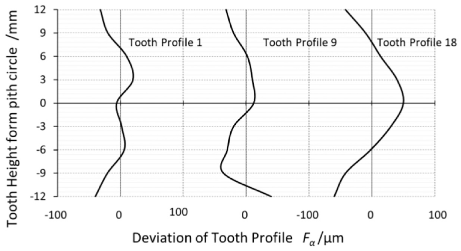
Deviation of left tooth profile.
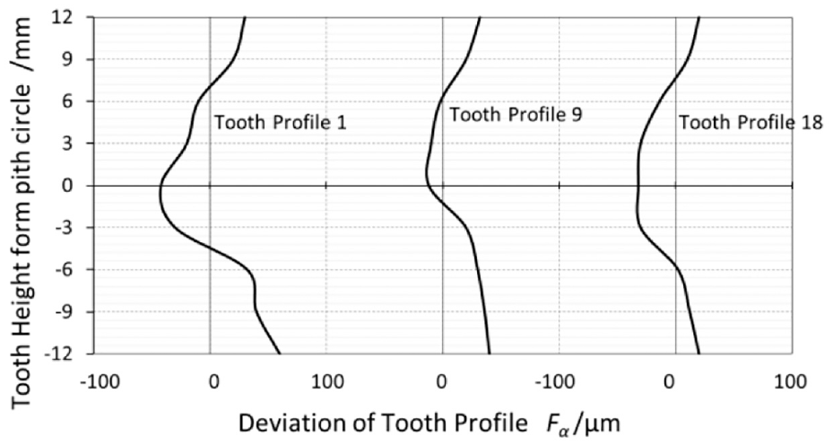
Deviation of right tooth profile.
According to ISO standards, the accuracy of gear is divided into 12 grades, which are arranged in the order of 0–12 from high to low. Grade 0 has the highest accuracy and grade 12 has the lowest accuracy.23,24 The accuracy of the gear obtained by hobbing can reach ISO 10-7; the accuracy of the gear obtained by grinding can reach ISO 6-5. 25 The gears used in automobile automatic transmission are usually ISO 5-7, and the gears used in other industrial reducers are usually ISO6-8. The measurement results shown in Figures 19 to 26 reflect the accuracy of the gear processed by the NC machine. The accuracy of this S-gear reaches ISO6 (see Table 4).
S-gear measurement values and ISO 6 accuracy allowable values.
Conclusion
This article presents an NC machining method for S-gear. The design, manufacturing and measuring of S-gear are introduced in detail. Based on the study, some conclusions can be drawn:
It is practical and feasible to produce S-Gear with the NC Machining Center.
The accuracy of the S-gear processed by the NC machining center reaches ISO 6.
The accuracy of gear NC machining is higher than that of gear hobbing, and slightly lower than that of gear grinding.
Involute gear and polynomial S-type gear can be expressed as a unified mathematical model.
S-gears can be automatically measured by CMM through programming; the measured data can be converted into the same measurement items as involute gear.
NC machining is especially suitable for single-piece or small-batch production.
S-gear has some advantages over involute gear. How to produce it efficiently and accurately is the main problem.
Footnotes
Appendix
Declaration of conflicting interests
The author(s) declared no potential conflicts of interest with respect to the research, authorship, and/or publication of this article.
Funding
The author(s) disclosed receipt of the following financial support for the research, authorship, and/or publication of this article: The authors are grateful for financial support from National Key Technology Support Program of Jiangxi China under Grant No. 2017ACB20038.