
Abstract
This paper designed a 7-DOF redundant robot manipulator that can flexibly and efficiently pick-up random objects. The developed 7-DOF machine with an additional redundancy achieved great progress in terms of flexibility and efficiency in the operational space. A robot operating system (ROS) was used to configure the manipulator system’s software modules, supporting convenient system interface, appropriate movement control policy, and powerful hardware device management for better regulation of the manipulator’s motions. A 3D type Point Cloud Library (PCL) was utilized to perform a novel point cloud image pre-processing method that did not only reduce the point cloud number but also maintained the original quality. The results of the experiment showed that the estimation speed in object detection and recognition procedure improved significantly.
The redundant robot manipulator architecture with the two-stage search algorithm was able to find the optimal null space. Suitable parameters in D-H transformation of forward kinematics were selected to efficiently control and position the manipulator in the right posture. Meanwhile, the reverse kinematics estimated all angles of the joints through the known manipulator position, orientation, and redundancy. Finally, motion panning implementation of manipulator rapidly and successfully reached the random object position and automatically drew it up to approximate the desired target.
Introduction
Robot manipulator, the most widely used industrial machine in production, was first introduced by Joseph F. Engel Berger in 1956. 1 It does not only work as an assistant, saving manpower, but also helps improve the quality, reliability, and accuracy of production. Due to great improvements in control technology for service machine and the immense amount of automation required in the electronic industry, the utilization of robot manipulators expanded from the traditional heavy industry to the electronic industry and other related smart factories. 2 The modern robot for the electronic industry should be light and handy, able to move quickly, low-powered, and have high degrees of freedom (DOF). All these are possessed by the Light Weight Robot (LWR) developed in 2003 through the cooperation between the Deutsches Zentrum für Luft- und Raumfahrt e.V. (DLR) and the KUKA Company. Consequently, a lower cost 3D vision device has become a popular product in the last decade. These 3D vision systems were developed mainly by applying the principles of robotics and related industrial engineering applications. The 3D vision machine is the primary technology that manipulates the autonomous system of a robot; it can detect objects, analyze distance, and several other functions. Meanwhile, more autonomous robot systems regulate the parameters to achieve greater valuable functions. 3 Recently, machine vision has been considered a powerful technology as it could rebuild object surface. It provides a robot with observation and recognition abilities, which could be used even in an unknown environment, needed for various requirements. 4 The biggest challenge in 3D vision application is to solve the problem of randomized bin picking. Object position and related contour pose are identified by the 3D vision module, which are then picked-up and placed into the right container by the manipulator.5,6 Even the proponents of 3D vision technology that created its first novel robot application have made it their great mission to explore its potential in the future business market. If a robot has quick recognition and skilled manipulation abilities, it will have the capacity to perform the same manual tasks done by humans, reducing the needed manpower.
Current researches in robot manipulator mainly focused on the architecture of the 7-DOF. Although the 6-DOF type machine is able to handle most normal tasks in some applications, the more advanced 7-DOF robot machine is highly viable in picking tasks even in unexpected conditions due to its additional DOF.7,9 In this paper, a 7-DOF redundant manipulator system was designed to improve its elasticity, stability, and efficiency in operational space. 10 The smart vision system is rapidly becoming a trend worldwide; researches on machine vision include object recognition,11,12 object pose evaluation, 13 and trace and localization applications. Object recognition and object pose evaluation allow a robot to efficiently catch the target and are indispensable technologies that warrant further studies.14,15 The present research manipulated an Intel RGB-D camera to fetch a real scene from the point cloud data. 16 The developed algorithm implemented a 3D object recognition and pose estimation system based on the Point Cloud Library (PCL). 17 The PCL includes different modules such as filter, segmentation, and other image retrieval technology in 3D image processing applications. It allows flexibility in designing software that deals with a higher degree of image data representation.
This paper is presented in several sections. Section 2 explains the redundant robot manipulator architecture and related specifications in the design, and discusses the computational redundant robot kinematics in the manipulator system. Section 3 describes in detail the posture planning for random object drawing of the 7-DOF manipulator structure. Section 4 discusses the simulation and implementation results of the 7-DOF redundant manipulator system. Finally, Section 5 presents the conclusions and suggestion for future studies.
7-DOF redundant robot manipulator designs
The architecture design of the developed 7-DOF redundant robot manipulator utilized the robot’s motor to support the whole mechanical plant. The redundant structure was designed to improve the flexibility ratio in the operational space and to extend the joint limiter of the robot manipulator. 18
Figure 1 shows the software and hardware system architecture configurations consisting of three main parts: (1) system interface, (2) movement control, and (3) hardware device management. This was designed as a closed-loop control system with its interface receiving user’s input commands and/or the sensory information coming from the outside. Its motion strategy calculates the required module function to push the movement of the manipulator in the hardware device. The Arduino-based controllers were employed to regulate the electric power of the suction cup through the connected network.
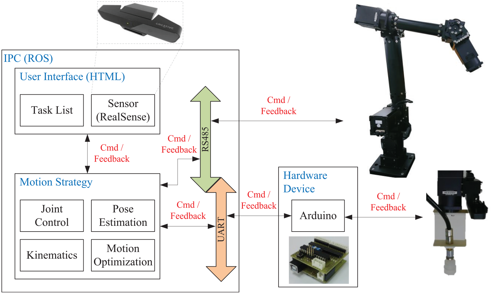
Software-hardware system architecture of 7-DOF redundant manipulator.
The Robot Operating System (ROS) was employed to configure the manipulator software module in the system structure. A node was designed as an application service in ROS. Each node’s connection was constructed with a specific topic, service, and action module to approach the prototype. A function in node was developed to conveniently replace and update the module for various applications. Through this, designers will be able to rewrite a favorable code to generate a new module in the ROS. The ROS utilized in this study supports a cross-platform and is able to work on various programing formats for fitting the desired applications of the robot system.
For the redundant manipulator kinematics, this study focused on the kinematics derivations of two different manipulator structures (i.e. redundant and non-redundant types). Position and orientation derivations for the traditional manipulator with non-redundant 7-DOF structure are always designed by Euler angle.19,20
Figure 2 shows the Euler angle definition. The roll, pitch, and yaw indicate the amount of rotation in the x-axis, y-axis, and z-axis respectively. The paper follows the appropriated Z-Y-X rotation to approach the desired targets. Symbols α, β, γ are sequentially denoted as roll, pitch, and yaw, respectively.
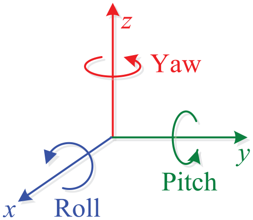
The roll-pitch-yaw rotation.
The Euler rotation matrix is calculated using formula (1):
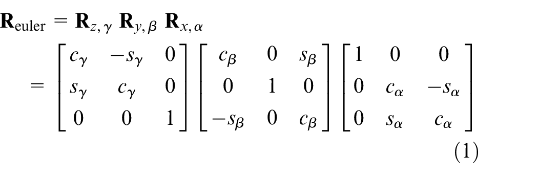
where:
c is the cosine function,
s is the sine functions,
The end-effector orientation matrix of manipulator is converted into the Euler rotation angle through formula (1). The final response is obtained by formula (2):
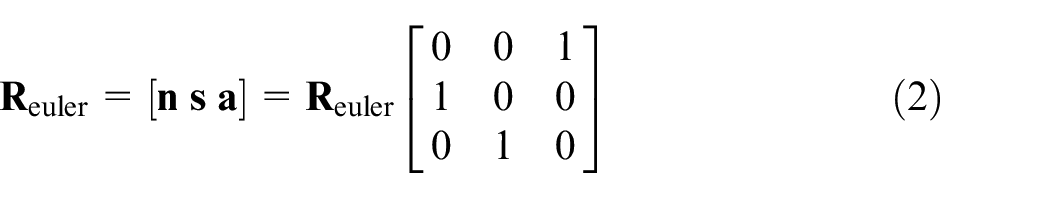
where:
In the kinematics derivation of redundant manipulator, its orientation and position were taken the same way as the non-redundant manipulator. Figure 3 shows the redundant manipulator with an added redundant axis in the dotted box, which supports the auxiliary mechanism to keep the manipulator in the same orientation and position. This allowed the elbow to move into the wrist and around the shoulder with the guiding vector.
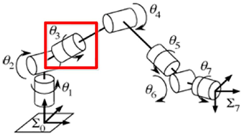
Movement of the redundant manipulator in the work space. 21
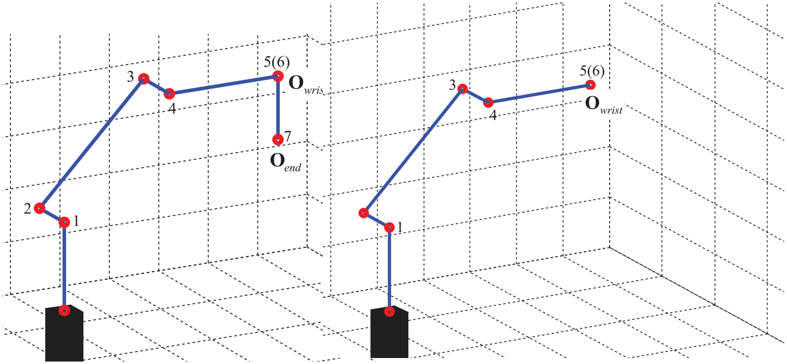
Figure 4 shows the movement of the manipulator in a circular trajectory, also called the null space. This provided the manipulators with more flexibility and extended its work space and joint movement up to its maximum limit. Its disadvantage in reverse kinematics have unlimited solutions; an additional redundancy (Ψ) was taken by the search algorithm to obtain the best solution.
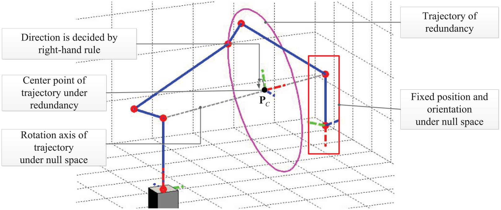
An example characteristic of the redundant trajectory.
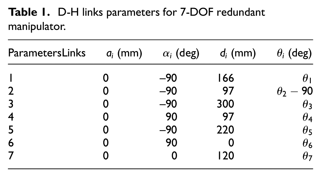
This paper utilized the Denavit and Hartenberg (D-H) link parameter table to show the relationship among the related links’ position and orientation and to develop the 7-DOF redundant manipulator. Each link’s coordinate system is shown in Figure 5 and the D-H Parameter values were selected based on Table1.
D-H links parameters for 7-DOF redundant manipulator.
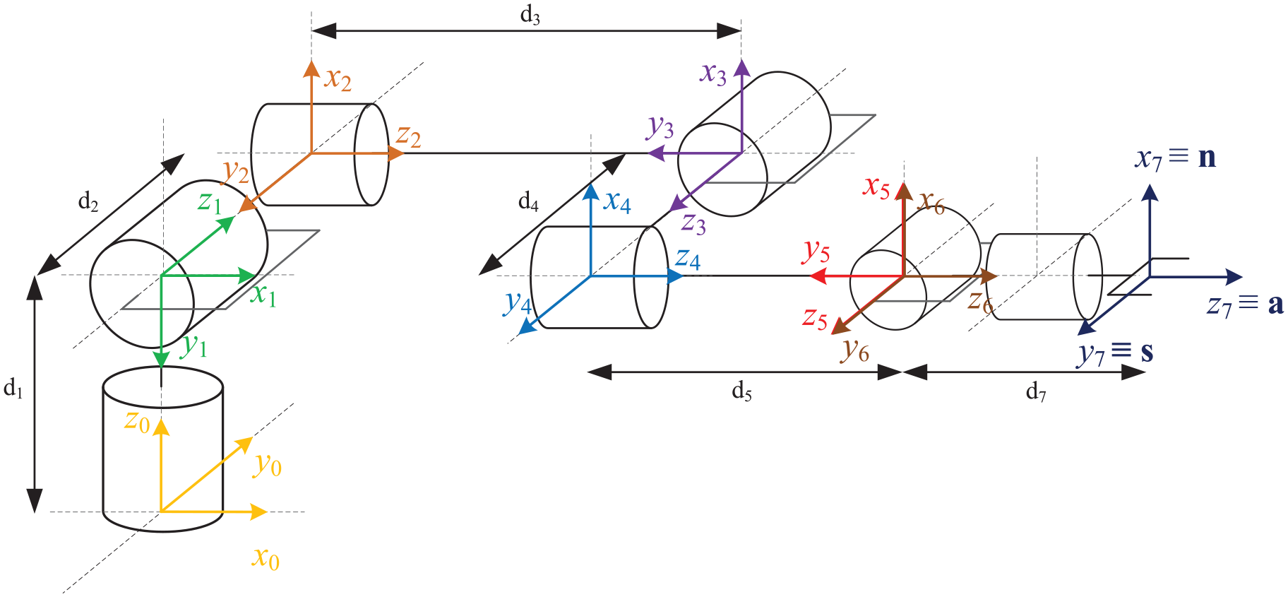
Coordinate configuration for 7-DOF manipulator.
In the design objective of the 7-DOF forward kinematics, the known joint angle from end-effector of arm was proposed to estimate its current position, orientation, and redundancy. In forward kinematics approximation procedure, the D-H transformation matrix was proposed to obtain the position and orientation at the end-effect of arm. This paper reasoned out the redundancy with the calculation of the vector formula.
In the end-effect position and orientation of manipulator, this paper proposed the D-H method to configure the link parameters in the table list. The link angle was sequentially assigned into the following D-H transformation matrix using formula (3).
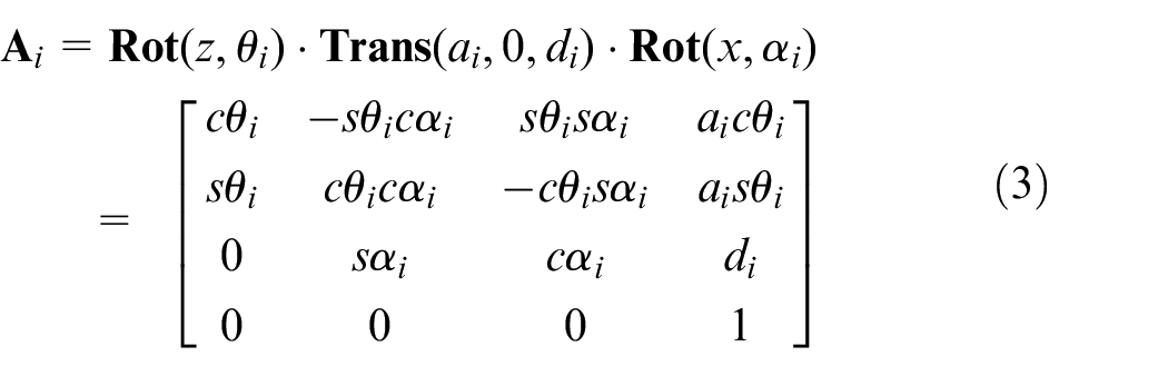
where:
This paper exported the D-H transformation matrix of 7-DOF redundant manipulator through formula (3). Each D-H Conversion matrix was obtained with serious multiplications to achieve the position and orientation by ma
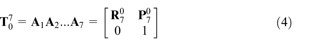
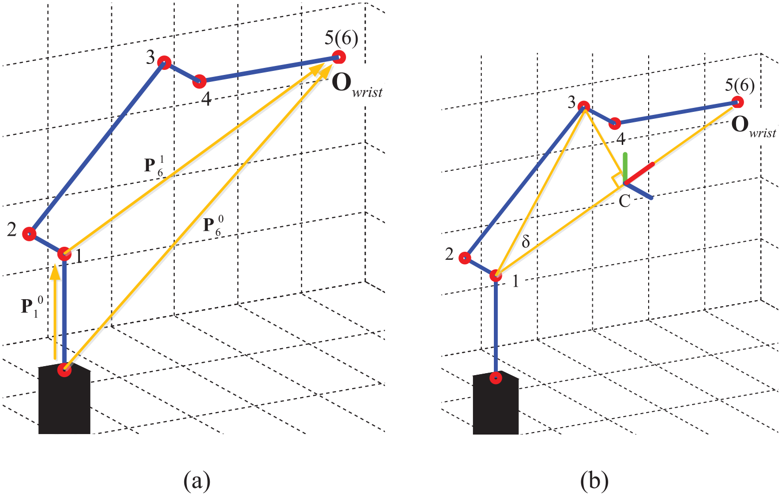
The redundant manipulator was observed to find the coordinate vector between the redundant center of the circle and the elbow. The vector angle was then produced while the redundant was approximated to zero. Figure 6(a) and (b) show the top view and side view, with the redundant value equal to zero; and Figure 7 illustrates the traced redundant values derived by formula (5).
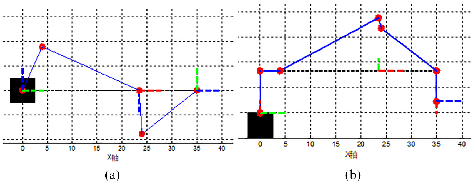
Illustration for zero redundant angle condition: (a) top view and (b) side view.
Illustration of redundant traces.
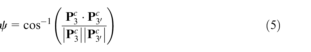
In formula (5),
The design of the 7-DOF inverse kinematics was meant to estimate the angle of each joint through the known terminal position, orientation, and redundancy of manipulator. Reverse kinematics of manipulator is normally configured through the conversion matrix to get the required robot motion. The present paper’s developed manipulator is suited for a spherical joint feature; therefore, the complex kinematics decoupling method was simplified for the inverse kinematics of the manipulator. Both kinematics for inverse position and inverse orientation were proposed to get the angles of the first four axes and the three rear axes, respectively.
In kinematics decoupling procedure, the manipulator was approximated to a spherical joint feature from the fifth axis to the seventh axis. Three previous bearings of the z-axis intersected at the original coordination; this point was then set as the wrist center (
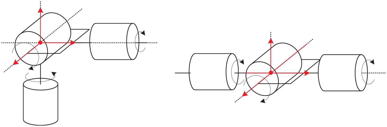
Illustration of spherical joints structure.
Kinematics decoupling procedure and its center position for wrist.
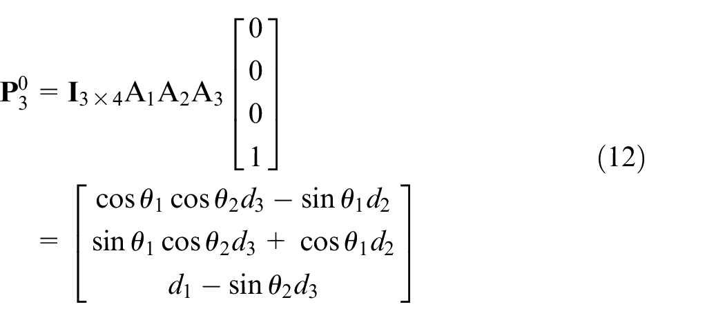
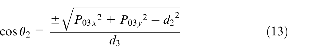
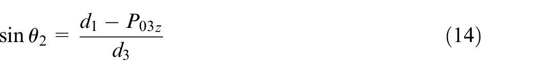
The complexity of the kinematic decoupling method was reduced through the inverse position kinematics procedure. Calculation results approached the joint angle of the first four axes through triangle geometry and vector operation. Position solutions for inverse kinematics were approached in three stages: (1) elbow joint, (2) base rotation and the fourth axis, and (3) redundant joint.
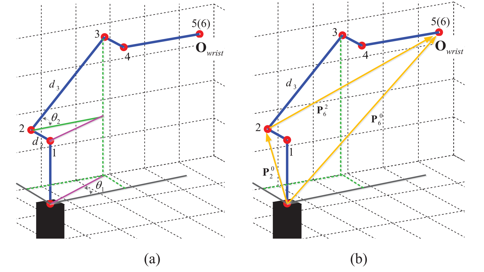
Figure 10 shows the elbow joint solution in the second axis. The shoulder joint position and rotation matrix of redundant circle center were first obtained. This function is similar to the forward kinematics. The
Solution for the elbow joint: (a)
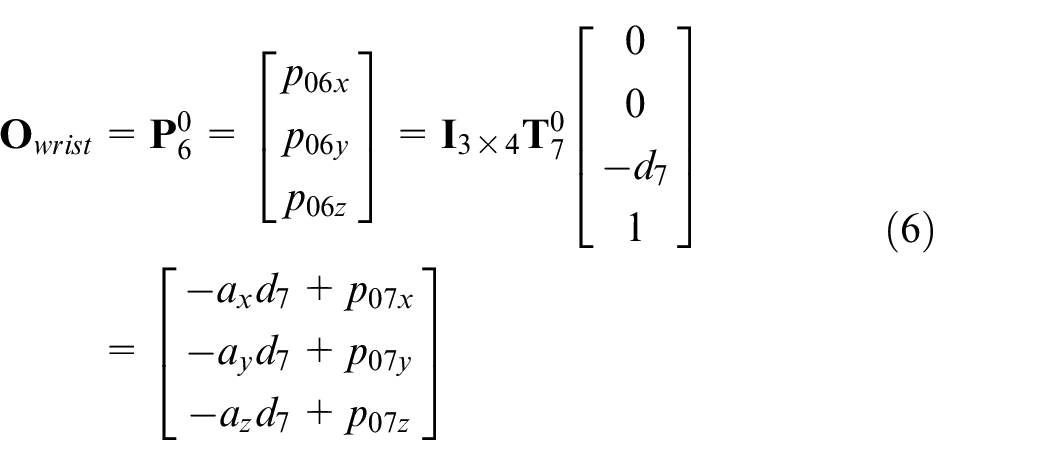
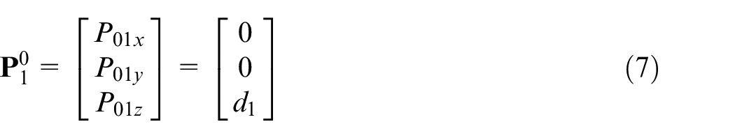

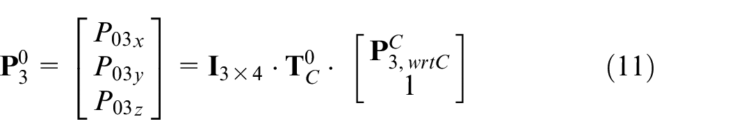
Based on previously obtained information, formula (9) was used to determine the coordinate positions (

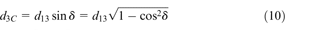
The terminal position of elbow joint through vector operation was calculated using formulas (10) and (11).
Finally, the D-H conversion matrix (
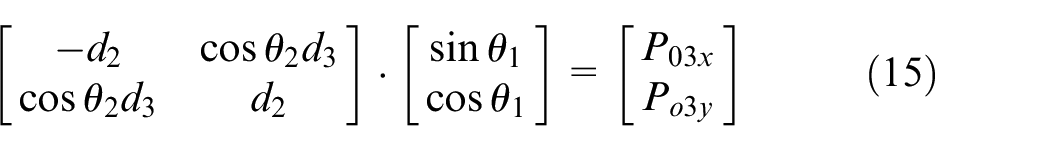
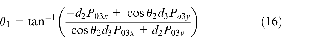
The solution for the base rotation was obtained by using
Solutions for the base rotation: (a) first axis and (b) fourth axis.
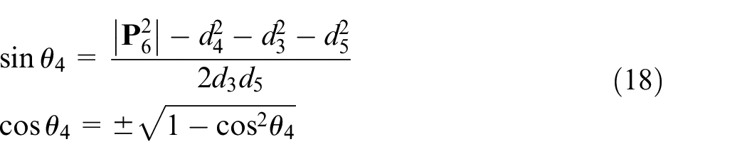
The fourth axis was calculated using the vector operation in formula (17). Based on the cosine theorem, the angle of the fourth axis was obtained through formula (18).
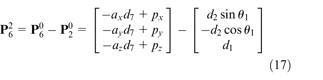
Further, the transformed second joint position coordinates
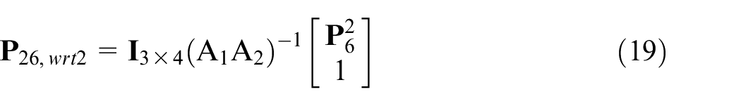
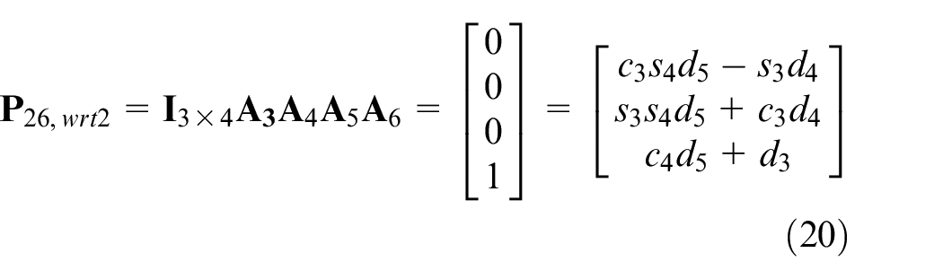
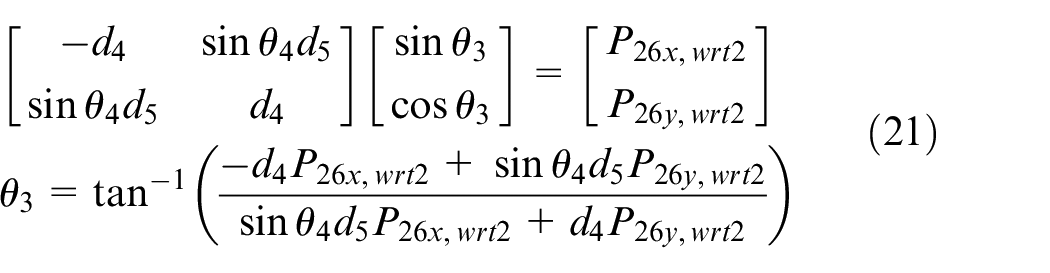
Having known the value of
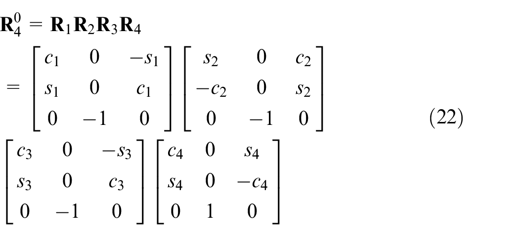
In the inverse orientation kinematics design, it was assumed that a series of angles in the fourth axis could be obtained from the previous inverse position kinematics. Rotation link matrices from the first to the fourth axis were revealed by the matrix form in formula (22), where
Meanwhile, the rotation matrices from the fifth to the seventh axis were defined by formula (23).

The

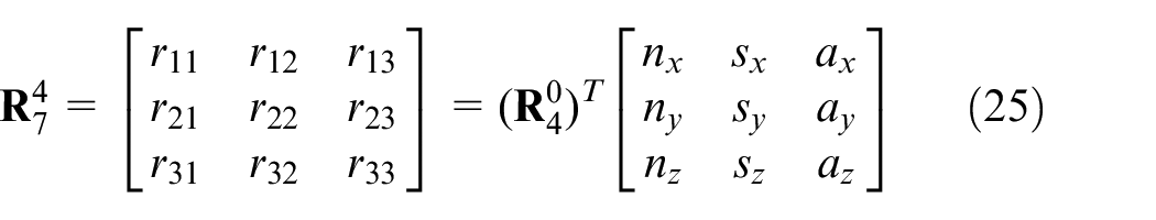
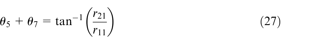
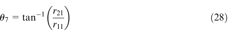
With formula (25), the angles for the fifth, sixth, and seventh axis were derived using formula (26).
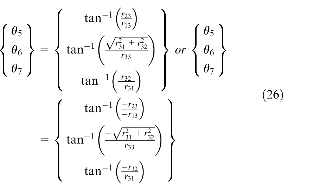
Since the z-axle is almost parallel between the fifth and the seventh links, that is, θ
6
= 0º or 180º and c6 = ±1, s6 = 0, a singular solution for the wrist joint was obtained; however, it was not possible for θ
6
to θ
7
to be analyzed individually. Due to
Null space optimization
The purpose of null space optimization is to find an optimal redundancy degree that would allow the manipulator to move within the shortest amount of time and least kinematics constrain, that is, joint limiter and singularity. A simple search method guided by an objective function was done to find the appropriated redundancy that does not only avoid joint limiter and singularity, but also achieves minimum motion time.
The objective function includes motion cost time evaluation, joint limiter, and singularity detections. Using the theory of trapezoidal trajectory, the motion cost time Ti of joint i was obtained by formula (29), which is further expanded into formula (30)
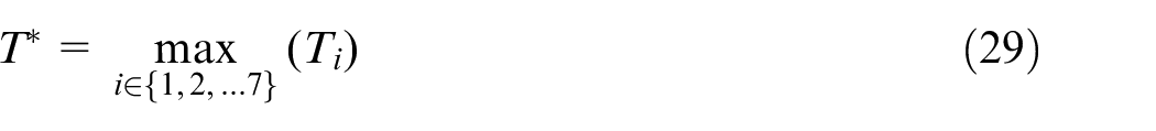
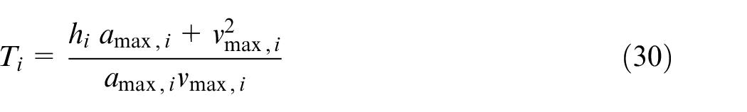
where:
hi is the movement degree of joint i,
vmax, i is the maximum velocity of joint i,
amax, i is the maximum acceleration of joint i.
The singularity detection procedure consists of wrist-singularity and shoulder-singularity. In this procedure, the constant δ is defined by the designer in advance. Wrist-singularity occurs when θ 6 becomes either smaller or larger than the δ. This is illustrated in formula (31).
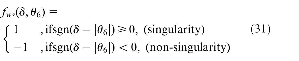
On the other hand, shoulder-singularity occurs when
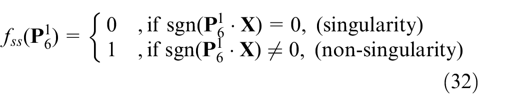
Joint limiter detection happens when one of the joints reach its maximum or minimum degree. This is illustrated in formula (33).

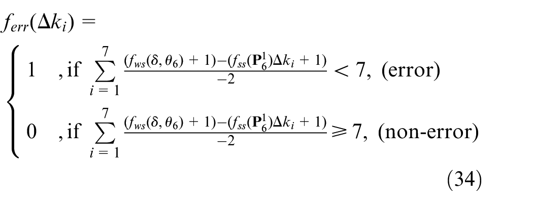
Formula (34) illustrates the final detection. The robot manipulator is considered over the joint limiter or in singularity when the signal is equal to 1; if the signal is equal to 0, it is regarded as a non-error condition.
Moreover, to estimate the motion time subject to kinematics constrains, formula (35) was utilized.
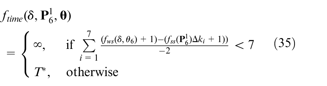
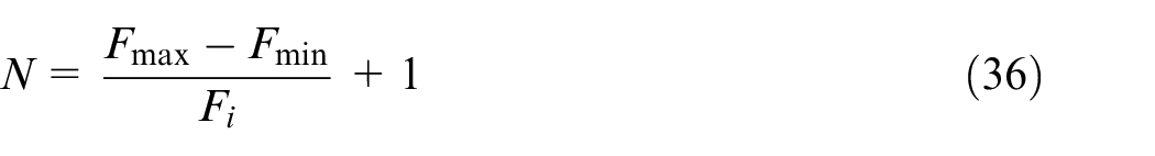
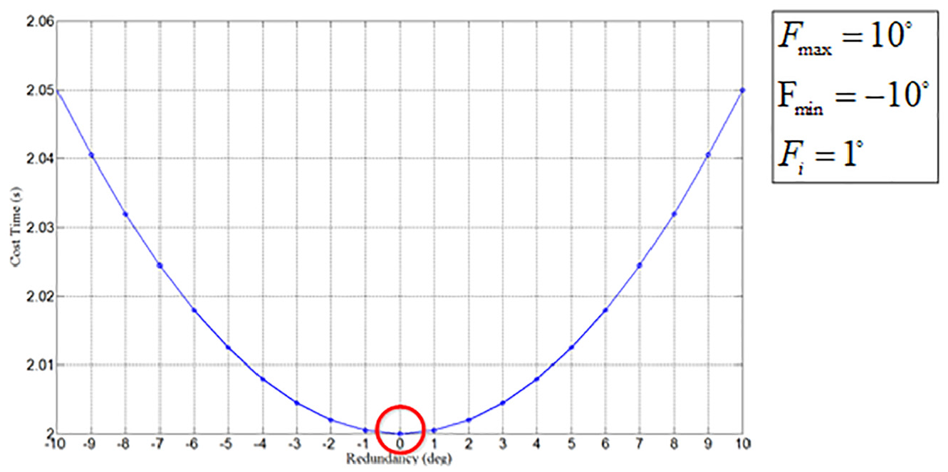
Figure 12 presents the estimated motion cost time during the first stage of the proposed two-stage search algorithm. When the searching range is set from Fmin to Fmax, the cost time in every Fi degree could be predicted, and the areas under the two red circles are considered the best redundancy degrees. Consequently, the output of the first stage will be received by the second stage, and its searching time could be achieved using formula (36). The area under the red circle in Figure 13 demonstrates the best minimal cost time.
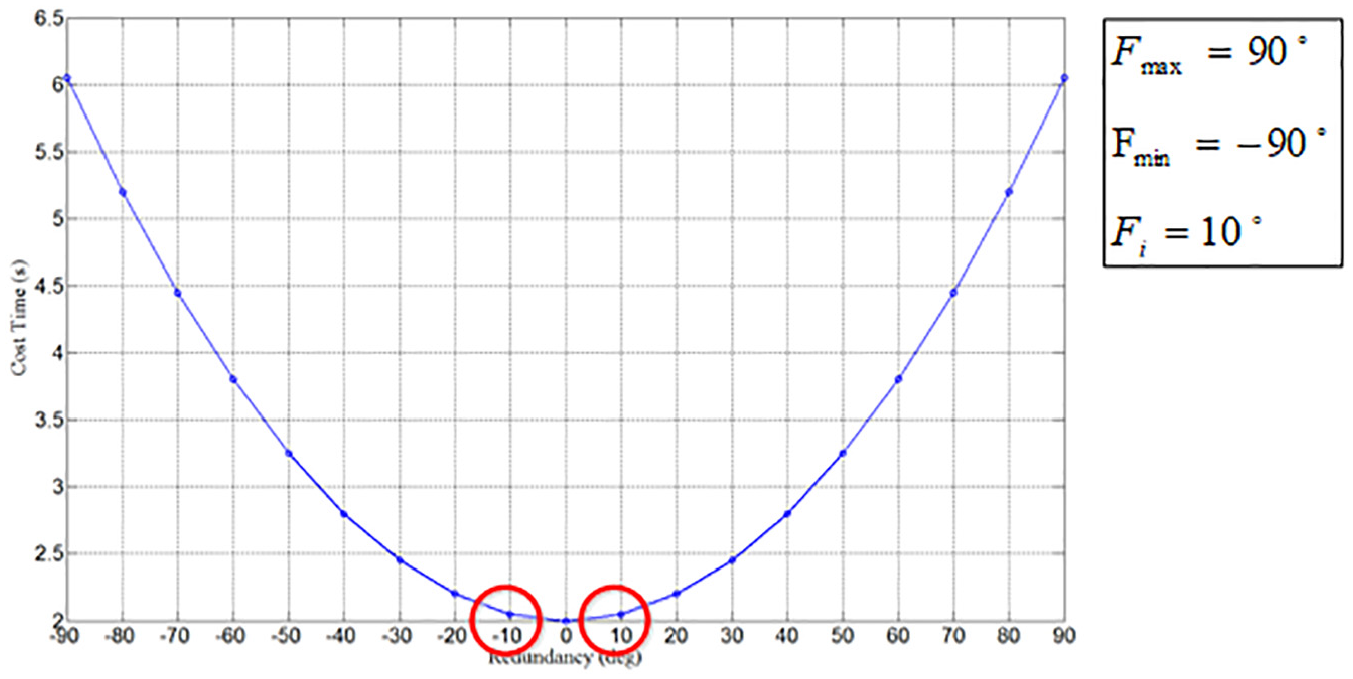
Searching result in the first stage.
Searching result in the second stage.
Posture planning for random object drawing
This section involves the three-dimensional pose estimation and manipulator motion panning for sucking random objects. A point cloud contains a set of point in multiple spaces. In this study, the PCL belonging to the big cross-platform was used to implement the image processing algorithm for data analysis. It includes 3D point cloud, filter, segmentation, feature detection, and point cloud matching.
For the object detection and recognition stage, a 3D camera was installed to capture an image of a certain external object. The image was then converted into a four-dimensional point cloud in the form of XYZ-RGB. After, preprocessing consisting of three phases (see Figure 14) was employed. The first phase involves passing through a filter to remove some points in the designated area 22 ; the second and third phases involves down sampling 23 and removing outliers, respectively24,25 to reduce the amount of point cloud. Through preprocessing, the point cloud data computation was increased. After preprocessing, a segmentation algorithm was utilized to detect an object, and finally, normal estimation was done to find a normal vector.
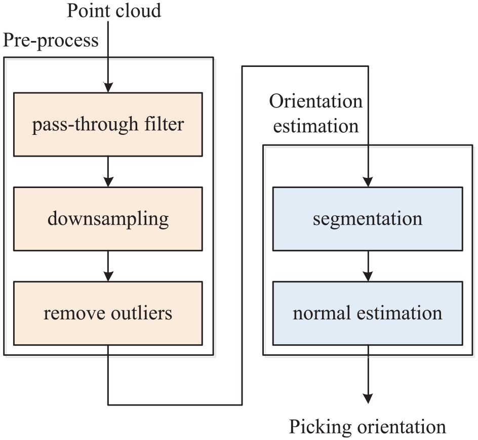
Flow diagrams for object detection and recognition.
Point cloud data preprocessing is an indispensable stage needed to increase the speed of data computation. Real-time information captured by the camera is converted into a point cloud set. Data preprocessing functions to remove outside points within the specified data range. Its advantages include reducing the number of point cloud and filtering outlier data noise.
When a point cloud passes through a filter, noise data is removed in the specified range. Figure 15 illustrates the final result based on the specification limit in the z-axis. As presented in Figure 15(a), points with a distance of more than 0.3 units from the specified range were deleted, while those with a distance of less than 0.3 units were preserved (Figure 15(b)).
Point cloud after passing through a filter: (a) filtered region (z > 0.3) and (b) reserved region (z < 0.3).
Due to inefficiency in obtaining big amounts of point cloud, this paper used primary sampling data to still achieve higher performance despite lower point cloud dataset. This is an efficient method to reduce point cloud dataset whilst keeping the original image precise. Outside points were handled by finding some isolated points in a different group and eliminating those noises in the specific limiter.
This paper developed a suitable filter to eliminate noise from the point cloud dataset. 26 It consists of two parameters namely, filter radius (r) and point cloud number (N) which is the number of points within the scanning region of the radius. Figure 16 shows that in a filter radius (red, yellow, and green points), when the point cloud number is greater than the defined N, the points will be preserved (red point); otherwise, such as in yellow and green points, the points will be removed. In Figure 17, the uncontained points marked with symbol × were removed in this process.
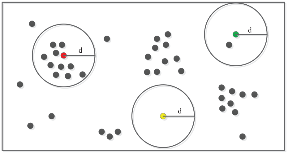
Filtering outlier points.
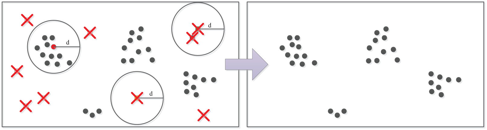
Result after filtering outlier points.
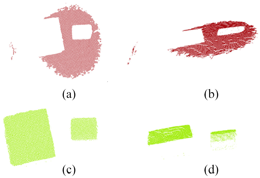
The next procedure involves the manipulator attaining the correct position for drawing object purpose through object posture estimation function. In this paper, it includes two phases, namely point cloud segmentation and normal estimation for the current object. The interesting object was separated from the whole scene through the image segmentation technology. Point cloud segmentation was then performed to explore the target object. A homogenous point within the same area was gradually selected through region growing segmentation 27 ; with this, a small area was extended by collecting the same character points to be rebuilt as the appropriated object. Initially, all point clouds were sorted based on their curvatures; the point with the smallest curvature is normally distributed in a flat region, and is usually selected as the starting point. This point was expanded within the same region to reduce the partition number of object. Consequently, a proper threshold was assigned to detect the object area where all small curvature points were gradually added into the same part. Figure 18 shows the distribution of output points forming the appropriate smooth surface in the green area.
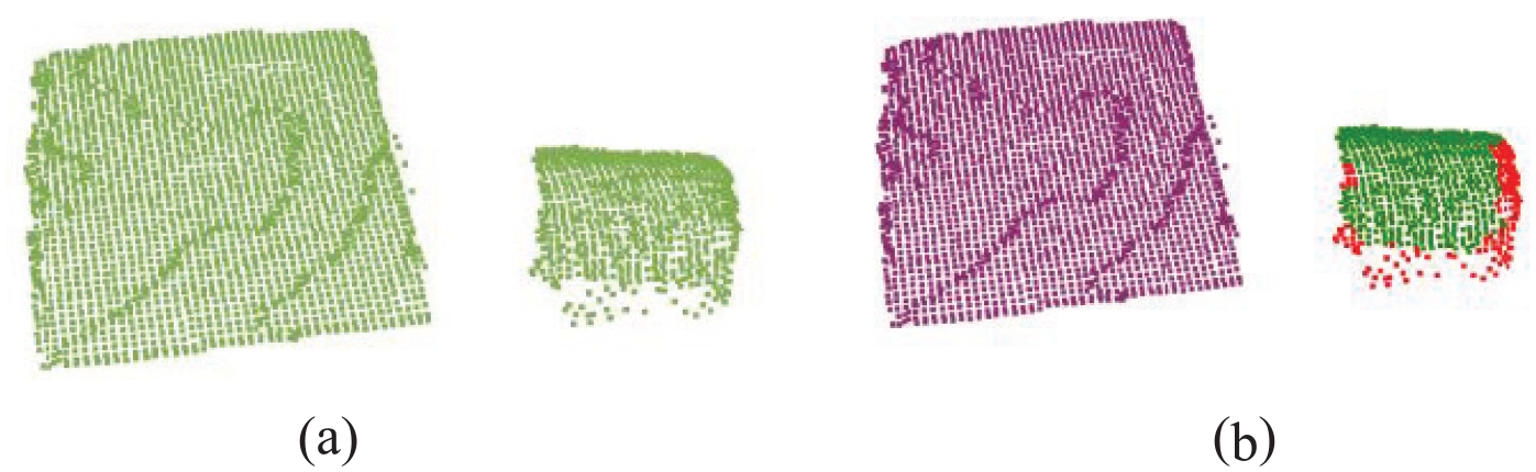
Results of region growing segmentation: (a) original point cloud (2882 points) and (b) region rowing segmentation (2721 points).
In object posture estimation procedure, normal vector estimation is an important aspect to form the geometric surface. This study captured a neighbor point cloud to form a surface normal vector. Figure 19 shows the normal object surface based on a set of point cloud.
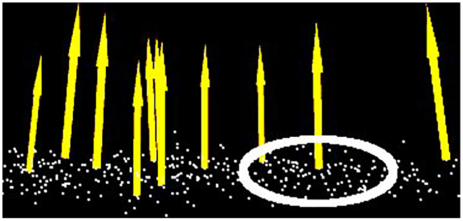
Normal vector surface.
The biggest dataset of point cloud with the maximum point number was selected to form the normal vector of object surface. Next, the center point (x, y, z) was calculated and its neighbor points were selected to get the average value. Finally, the resulting value, represented by the red arrow in Figure 20, was considered the normal vector (u, v, w).
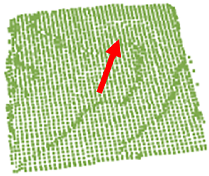
Normal vector on surface.
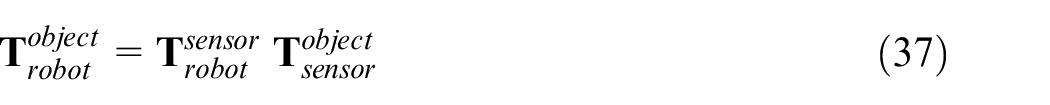
The transformed formula for matrix coordinate is discussed as the following equation (37):
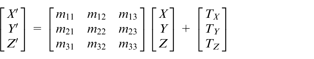
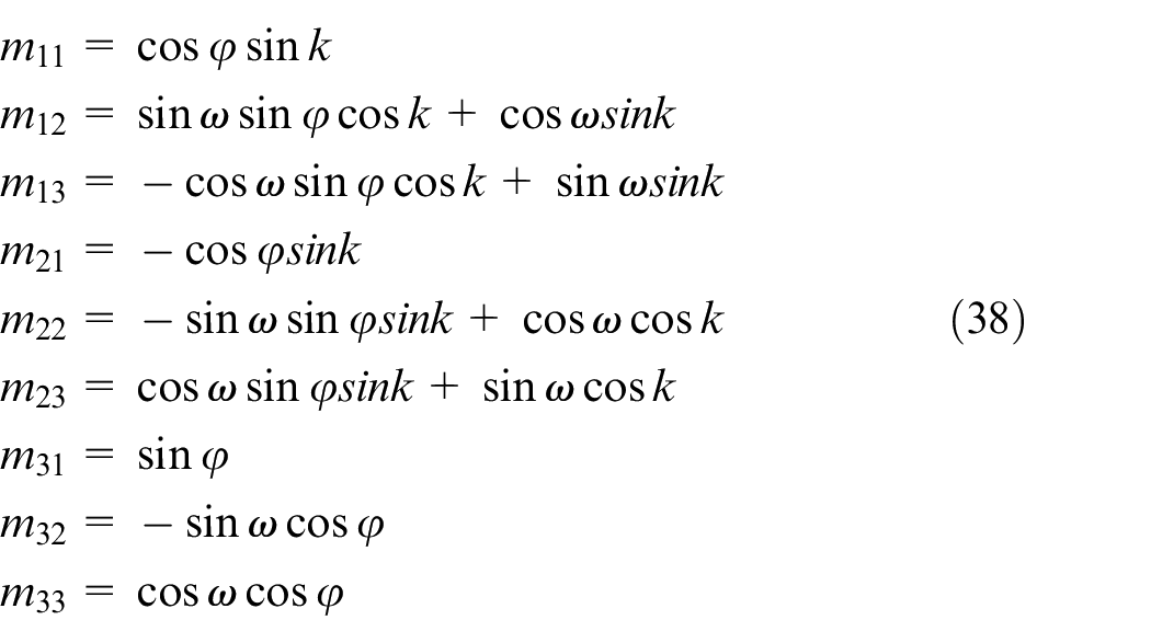
The manipulator in this study was designed to fetch a drawing object based on the current orientation information. Detail information is explained in Figure 21 and its coordinate was transformed by formula (38).
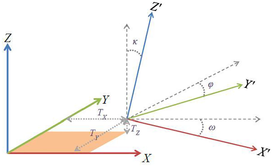
Coordinate transformation.
The absolute position and posture of object was obtained for the manipulator’s operation using formula (38). The inverse kinematic was applied to convert previous information into the end effect position; thus, the manipulator was able to move into the desired position to make the correct drawing action.
7-DOF redundant manipulator simulations and implementations
To verify the procedures for the 7-DOF redundant manipulator, this paper proposed the searching algorithm with positive and inverse kinematics approximations for the robot to have better control. The experiment was done in three parts: (1) kinematic theory validation, (2) null space motion control, (3) random object point cloud image segmentation, and (4) implementation.
Experiment 1: Kinematic theory validation
In this experiment, some specifications of the manipulator systems were defined in advance; a related inverse kinematic was used to approach the desired angle for each joint. These angles were imported into the positive kinematics to get the end effect positions and redundant angle of the manipulator.
Figure 22 shows the results of the practical operation. Both end-effect positions and orientations of the manipulator remained constant and only the redundant angles changed. The feedback error response between the angle and redundant is illustrated in Figure 23, and the command error response between end effects and redundant is plotted in Figure 24. The measured error for end effect position of the manipulator was smaller than 0.0001 cm; and all the feedback errors for roll, pitch, and yaw were smaller than 0.1°. These indicate that the actual manipulator system performed its purpose by only changing the redundant angle and maintaining the same end effect positions and orientation conditions.
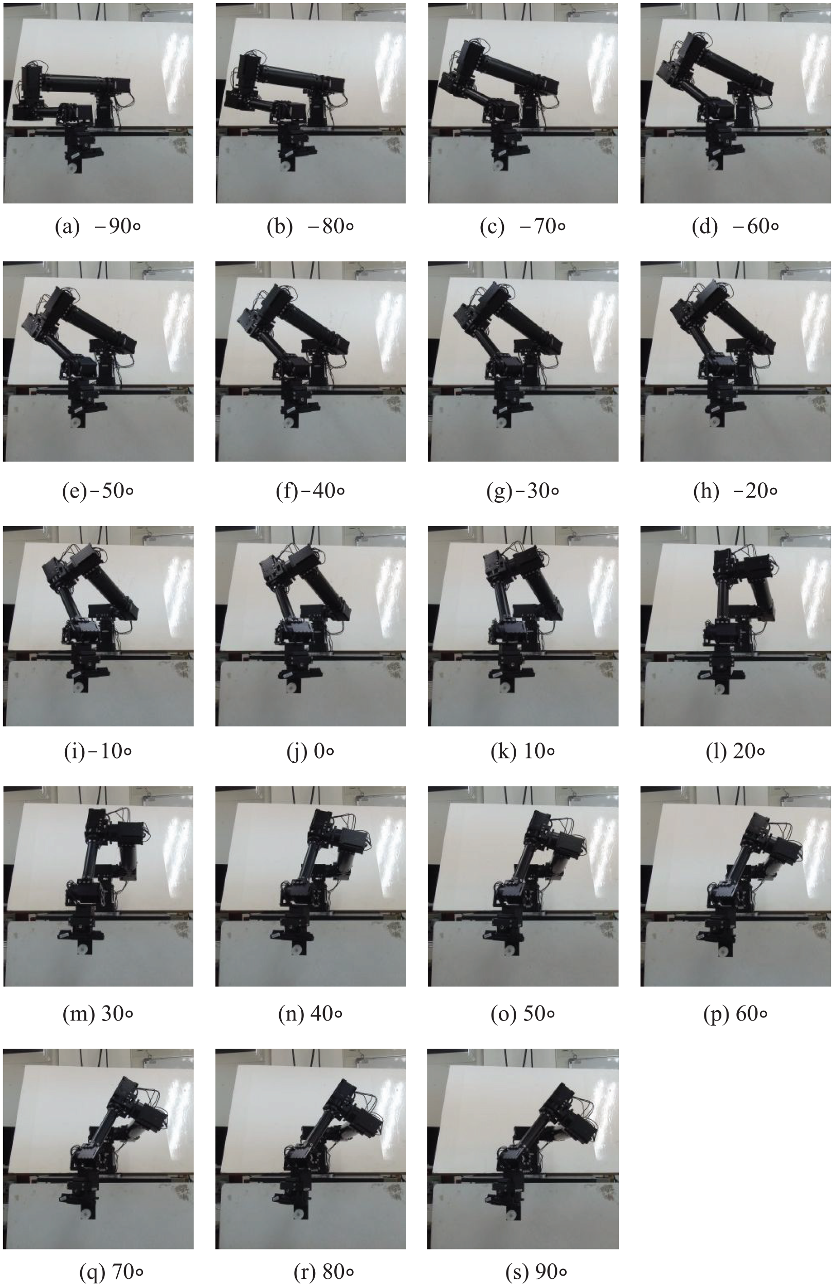
Results of the actual manipulator through nine sequential scenes.
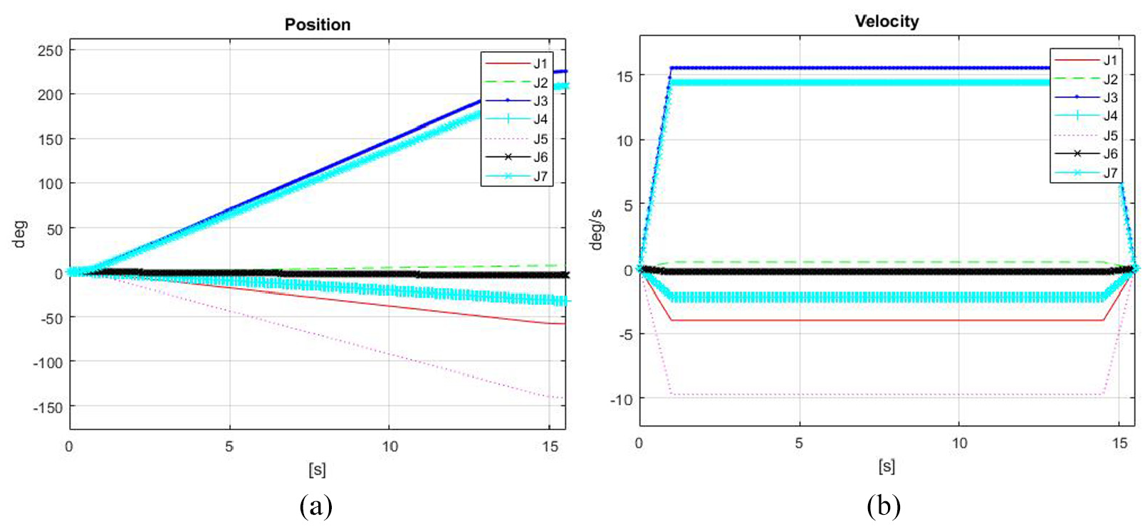
Joint position and velocity feedback of the actual manipulator: (a) joint position response and (b) joint velocity response.
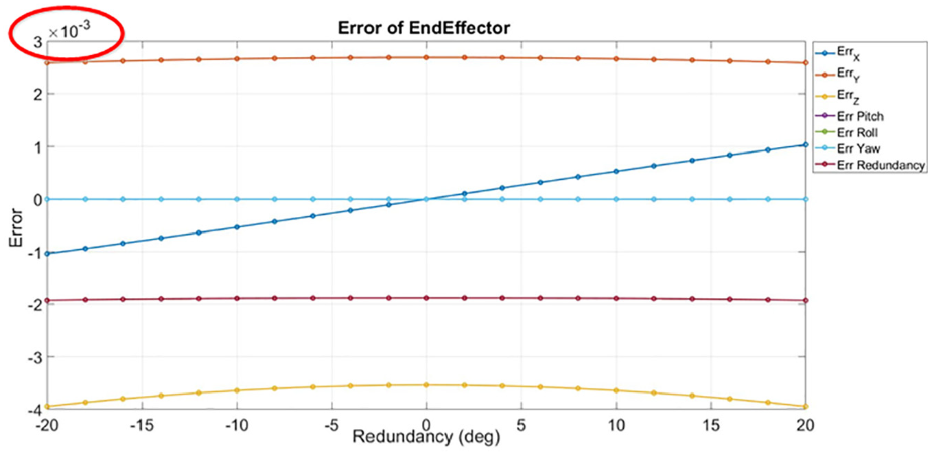
Error in the end effect and redundancy between command and feedback.
Experiment 2: Null space motion control for redundant robot manipulator
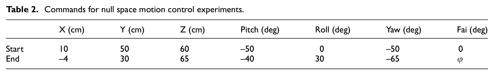
Table 2 presents the start and end conditions of robot commands used to verify the null space motion control with the proposed searching algorithm. Comparison of the results with and without null space motion control strategy was done in Experiment 3 which verified the advantage of redundancy. Moreover, the maximum and minimum degrees for all joints in manipulator are shown in Table 3.
Commands for null space motion control experiments.
Maximum and minimum degrees for all joints.
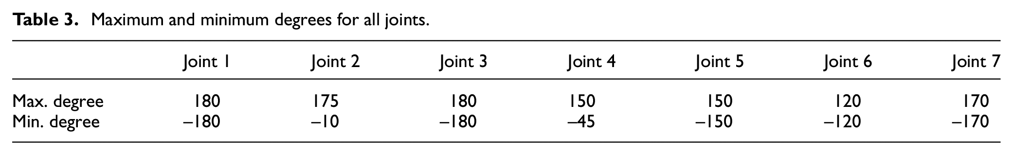
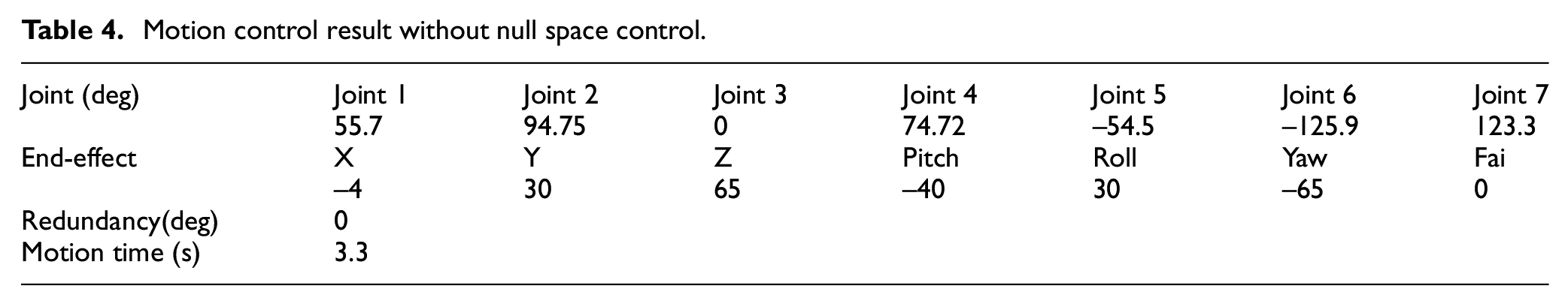
Table 4 shows the results of all joints in the without null space motion control strategy. The joint 6 was found to be over its minimal limit value of −120.
Motion control result without null space control.
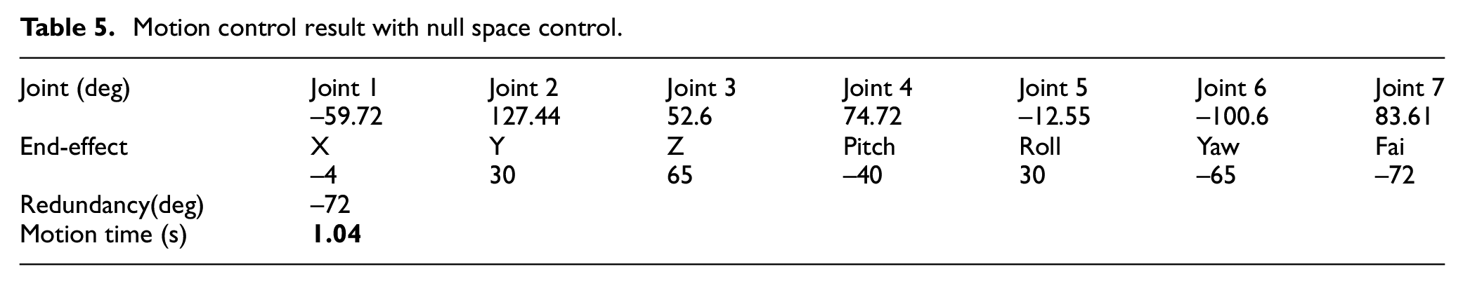
The results of all joints in the with null space motion control strategy are shown in Table 5. It was found that all joints did not exceed their minimum and maximum limits, and the total motion time obtained was only 1.04 s. Further, the motion time cost was reduced from the original 3.3 s to 1.04 s. Figure 25 shows a trajectory with null space control that performed an appropriate curve with the other without null space control response.
Motion control result with null space control.
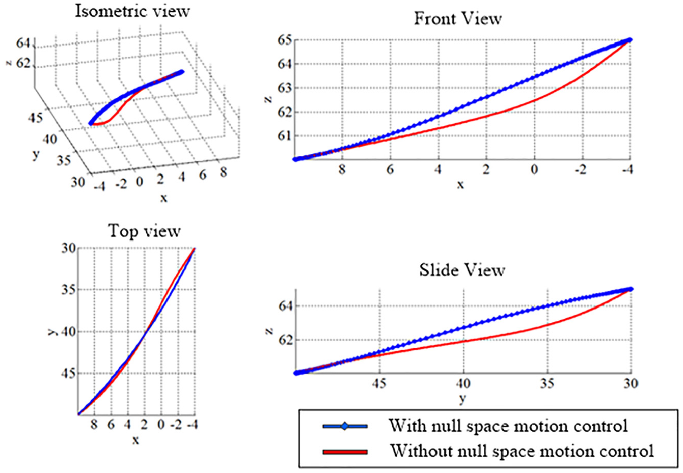
Trajectory comparisons with and without null space control.
Experiment 3: Random object point cloud image segmentation
To verify the random object point cloud image segmentation, this paper directly performed the preprocessing phases (passing through filter, reducing sampling number of point cloud, and removing the outlier point cloud) through point cloud image segmentation. Figure 26 shows the top view and side view of the objects captured. Figures 27 and 28 show the original point cloud and the preprocessed point cloud, respectively. As demonstrated in Figure 28(a), the number of original point cloud was reduced from 307,200 to 28,520 after passing through a filter, and Figure 28(b) shows that the point cloud number was reduced to 3043 (reduce rate = 89.3%) by the sampling operation. Finally, 45 outlier point clouds were filtered. In Figure 28(c), the remaining 2998 point clouds are shown. Based on the results of this experiment, it was found that the point cloud image feature was still very similar to the original image even if the point cloud number decreased from 307,200 to 2998 through the point cloud image segmentation.
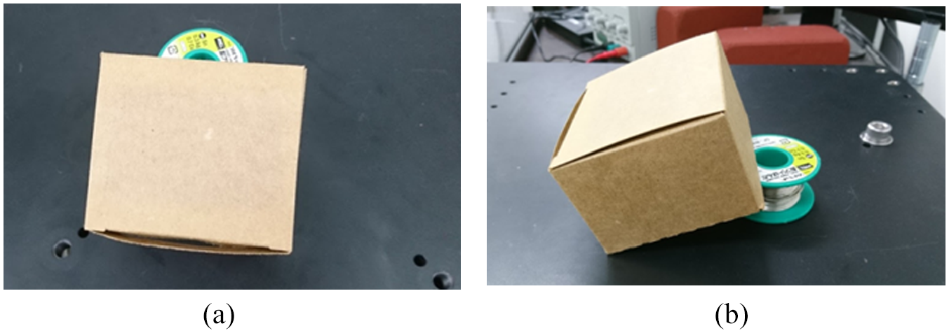
Object segmentation: (a) top view and (b) side view.
Original point clouds: (a) top view and (b) side view.
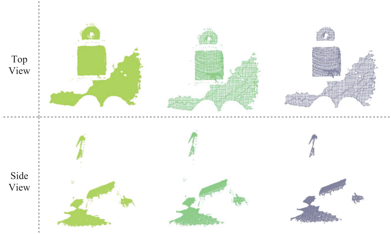
Preprocessing results of point clouds: (a) passing through a filter (point cloud = 28,520), (b) down sampling (point cloud = 3043), and (c) removing outliers (point cloud = 2998).
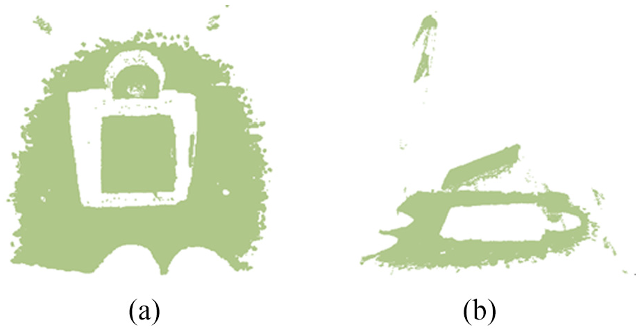
Figure 29 shows the separated point cloud result; the blue region is considered as the separated object by the region growing segmentation and the red area is an unidentified area (Figure 29(a)). The segmented object is shown in Figure 29(b).

Point cloud object segmentation: (a) region growing segmentation and (b) final segmented object.
Experiment 4: Implementation of the real posture planning manipulator for drawing object
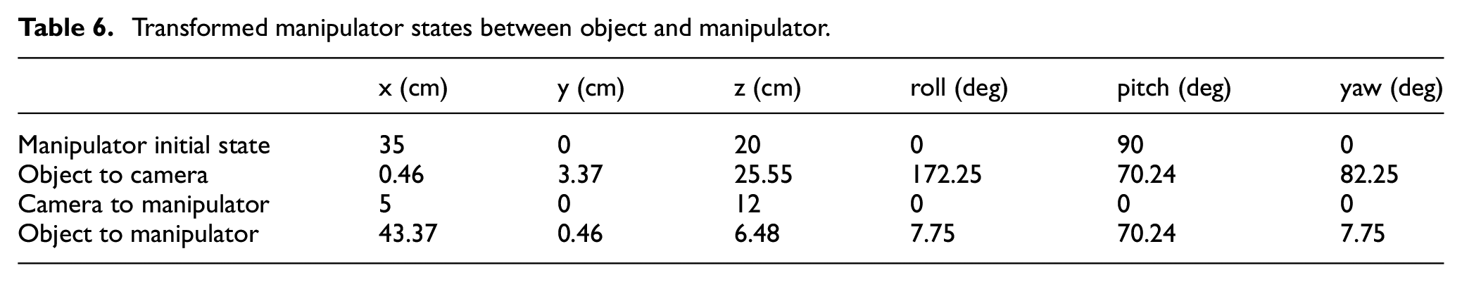
AS previously shown, the object’s posture was derived by formulas (37) and (38). One camera was located in the manipulator plant to acquire its center position and posture orientation with respect to the object posture. The transformed matrix was utilized to obtain the real center position and its posture’s orientation from the object to the robot arm. Table 6 lists the serious transformed states among the object, camera, and manipulator, including the center position (x y z), and posture’s orientation (roll pitch yaw).
Transformed manipulator states between object and manipulator.
Based on the inverse kinematic theory, the previous position and orientation information were converted to catch the end effects of the manipulator; thus, the manipulator was able to correctly move into the right target, completing the drawing object action. All successful drawing actions of the manipulator were plotted in eight sequential graphics and are shown in Figure 30.
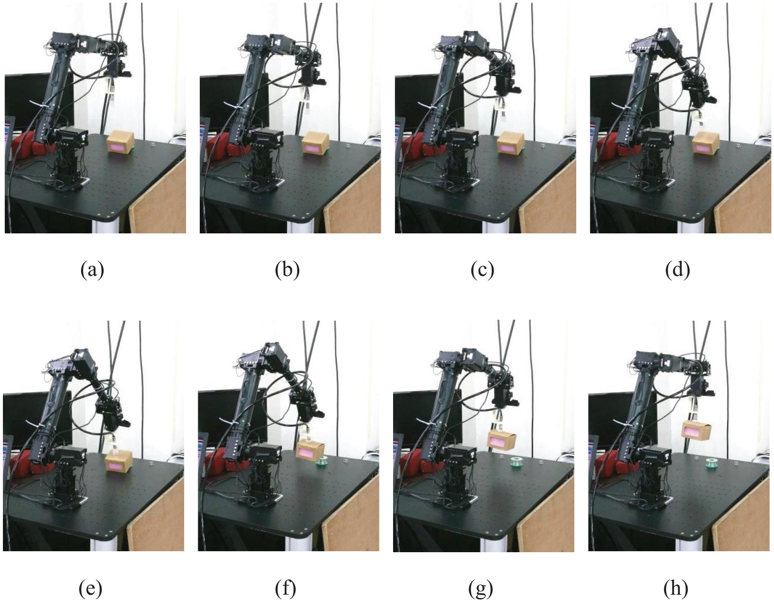
The actual manipulator drawing an object in eight sequential graphics.
Conclusion
This paper designed a kinematics control model of 7-DOF redundant manipulator system with null space optimization that can efficiently perform object drawing applications. A novel kinematics of manipulator with one additional redundant degree was used to provide unlimited solutions for problems usually encountered during its drawing action. A drawing action simulation was done by the actual manipulator to verify the developed kinematics model.
To obtain the posture of the random object to be drawn, 3D camera was used to capture point cloud data of the object. The point cloud algorithm was utilized to detect and recognize the object posture. In addition, the manipulator was able to estimate the drawing posture through data preprocessing which consists of passing through a filter, down sampling, and removing outliers. This was then followed by image segmentation and normal vector estimation to accurately detect the object.
The manipulator system was implemented in a real environment and was successful in recognizing the object posture and in efficiently drawing the object into the desired target. It is suggested that future studies use other optimal search algorithm that would allow the manipulator to perform more complex tasks needed in smart manufacturing applications.
Footnotes
Declaration of conflicting interests
The author(s) declared no potential conflicts of interest with respect to the research, authorship, and/or publication of this article.
Funding
The author(s) disclosed receipt of the following financial support for the research, authorship, and/or publication of this article: This paper was partly supported by the Ministry of Science and Technology of the Republic of China under contract MOST 107-2221-E-507-005 and MOST 107-2221-E-032 -048.