
Abstract
Industry 4.0 accelerates the growth of unmanned technology that reduces the labor cost and creates high automation in manufacturing system. The automated guided vehicle which is capable of transferring materials or executing tasks without human intervention becomes a necessary system for modern unmanned factories. The study explores the guidance and control design to accomplish the common task of path-following control for unmanned ground vehicles (UGV). A complete design method is presented that includes the lateral-directional autopilot, the vector field guidance for path-following, and multi-sensor fusion. The lateral-directional autopilot produces the low-level control action, the higher level guidance indicates the course direction of UGV at every spatial point based on the lateral path error, and the accurate UGV position relies on the estimate obtained by dynamically fusing sensors with extended Kalman filter. The design parameters in every stage are analyzed theoretically first and then fine-tuned in practice. The process is clearly described in this study, and the field test results are discussed in details to verify the performance of the proposed method and demonstrate the superiority over others.
Keywords
Introduction
The spread of unmanned vehicles in many directions—up (unmanned aerial vehicles on the air 1 ), down (autonomous underwater vehicles under the sea,2,3 and around the world (unmanned ground vehicles on the ground 4 )—extends the frontiers of human activity. As the ground is the main space for human activities, undoubtedly the unmanned ground vehicle (UGV) plays an important role in the unmanned trend of “Industry 4.0” for bringing many benefits, such as keeping personnel safety, lowering cost, improving efficiency and increasing productivity. More and more researches spur various design and applications of UGVs. A low-cost autonomous guided vehicle is designed to execute indoors patrol. 5 A robust levitation controller for maglev train against gravity change in the carriage is designed by adaptive sliding model based on neural network learning to improve the safety and comfort. 6 An automated guided vehicle combined with an industrial robot becomes a flexible automation system that is able to carry out large aerospace structures assembly. 7 A fleet of UGVs contributes the efficiency of unmanned factory by a hormone regulation for on-line scheduling of machines and vehicles. 8 Clearly the autonomy of UGV is the essential requirement for all these applications. The study aims at the development of a guidance and autopilot system for an all-purpose UGV to accomplish the path-following mission.
Guidance and control are the core issues of autopilot design. From top-down viewpoint, guidance is a high-level function providing the heading commands and control is a low-level function providing the servo commands. The design strategies for guidance and control are classified into three types: the separate design, the joint design, and the closed loop design. 9 The joint design and closed loop design are more complex. The separate design approach has a simple structure and is widely adopted.
In control design phase, the servo commands to the low-level autopilot system are designed to realize the movement from the high-level path-following demands. Two basic servo control of actuators are speed regulation and steering wheel position control. The kinematics of steering depends on the UGV configuration. Two types of wheeled UGVs are Hilare-type and car-like-type. The Hilare-type UGV have two independently driven wheels. Moving forwards/backwards and turning right/left are accomplished by controlling the speeds of two independent wheels. The Hilare-type UGV with zero minimum turning radius has good maneuvering ability. On the other hand the car-like-type UGV has independent mechanisms for speed control and direction control. One motor is required to control the steering wheel and the other motor is required to regulate the speed. As a result, both speed control and angular position control have to be designed. A comprehensive study of the modeling, path planning and control of Hilare-type and car-like-type mobile ground vehicles is given in Fahimi. 10
The kinematics between heading angle and steering wheel angle is the key mechanism to complete steering control of car-like-type UGVs. The resulting block diagram for UGV lateral-direction control has nested control loops. The inner loop takes in charge of the position control of steering wheel, and the outer loop takes in charge of the heading (course) control of UGV. The performance of the outer loop system is constrained by the performance of the inner loop system. It implies that the inner loop system has to be designed with the highest bandwidth without violating the saturation constraints of actuators. The successive-loop-closure approach is commonly used for the autopilot design with nested control loops. 11
In guidance design phase, there are two categories of design methods—trajectory-tracking and path-following. The difference between them depends on whether or not the time variable exists. The path-following method does not require a particular position at a particular time, but the trajectory-tracking method does. For a class of nonlinear system with the unstable zero dynamics, the trajectory-tracking method is affected by a limited tracking performance, whereas the path-following method is not. 12 In practical applications with environmental uncertainties, the path-following method works well that is superior to the trajectory-tracking method. 11 In Sujit et al. 13 five typical algorithms for path-following are evaluated for their performance of cross-track error, control effort, and robustness to disturbances. It concludes that the vector field path-following algorithm has the best performance for fixed-wing unmanned aerial vehicles. In aerospace and robotics communities the vector field method has been extensively studied to meet specific criteria and achieves successful results.14–17
To implement guidance design, the sensor plays a key role that helps a UGV to localize itself. There are various sensors including inertial sensors, global positioning system sensors, visual sensors, ultrasonic sensors, and laser scanning sensors.17–22 Because of the applicable range, limitation, and characteristics, in very rare cases only using one kind of sensors can obtain a satisfactory performance. As a consequence, multi-sensor fusion is a very important application that maximizes the benefits by combining the data from different kind of sensors through dynamic observer. The well-known Kalman filter is the most commonly used dynamic observer to optimally estimate dynamic system outputs by minimizing the covariance of estimation error.23,24 For some applications the system process model and measurement model are nonlinear. The resulting algorithm using Jacobian is called the extended Kalman filter (EKF). A number of UGV studies have made use of Kalman filter as the sensor-fusion approach to estimate precise position in practical guidance and control, as follows. For a small four-wheel differential drive unmanned vehicle the extended Kalman filter has been used to fuse the data from laser range finder and odometer for guidance in an indoor environment with landmarks. 4 A dual estimation algorithm is proposed to estimate system states and slip parameters by integrating two Kalman filters with AHRS (attitude and heading reference system) and two incremental encoders to overcome the slip limitation for the curve path-tracking control of a four-track wheel skid-steered mobile robot in concrete terrain. 20 In this study a cost-effective sensor-fusion system composed of a low-price GPS module and 3D orientation sensor is implemented by using extended Kalman filter to estimate position for path-following guidance and control of an all-purpose wheel-based outdoor UGV.
A complete design process for UGV path-following control is described in this research including the successive-loop-closure design for the lateral-directional autopilot, the vector field-based guidance design for path-following control, and the extended Kalman filter design for sensor-fusion of GPS and orientation sensor. The results of parameters determination and comparisons with different methods are reported in this article that are beneficial to researchers attempting to develop more autonomous UGV applications in different fields. The paper is organized as follows. Section 2 describes the materials, mathematical analysis, and methods for guidance and control design. At first the UGV configuration, hardware, and development software are introduced. The kinematics are derived next. Three primary design activities are described in sequence from the successive-loop-closure approach for lateral-directional autopilot control, the vector-based straight-line path-following guidance, to the extended Kalman filter design. Section 3 presents the design results and field test results. The parameters determination in guidance and control design are described in details, and the effectiveness of extended Kalman filter is demonstrated in field test results. Finally, the conclusions are stated in section 4.
Materials, mathematical analysis, and methods
UGV configuration, hardware and software
A three-wheel, car-like-type, outdoor UGV with one powered active dual-wheel in the front and two passive wheels in the rear is shown in Figure 1. The front dual-wheel is active with two 24 V DC motors that one motor is for traction and the other one is for steering. The passive wheels can independently rotate clockwise or counterclockwise. The UGV weight is 18 kg and its dimensions are 66 cm (L) × 44 cm (W) × 54 cm (H).
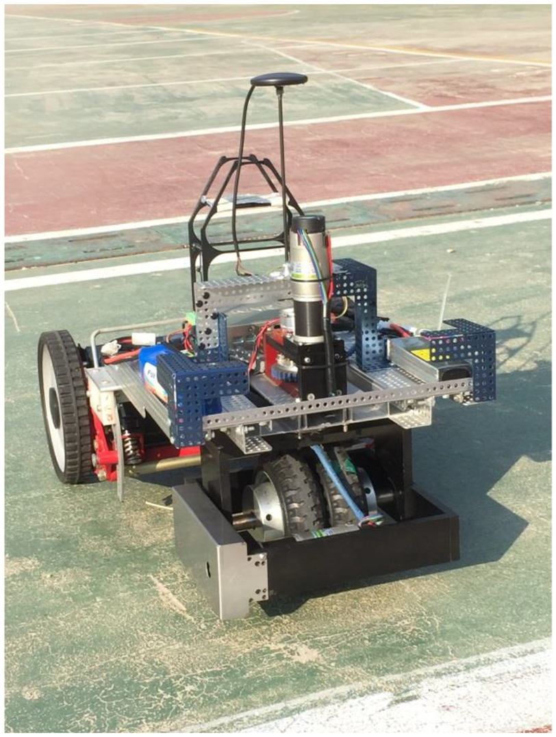
The three-wheel car-like-type outdoor UGV.
Two 24 V DC motors provide the powers of traction and steering independently. To increase the output torque the traction DC motor has a 1:64 gearhead of and the steering DC motor has a 1:96 gearhead. Additionally there is a 14:30 transmission gear system for both traction and steering motors outputs. Each DC motor is also equipped with a 16 ppr (pulse per revolution) encoder for feedback control. The designed cruise speed is close to a man’s walking speed 0.6 m/s.
Two types of sensors are used for guidance and control include a low-price GPS module and a 3D orientation sensor (attitude and heading reference system, AHRS). The GPS module—u-blox NEO-7—is used to provide the correct but low-updated position information. The 3D orientation sensor—InertialLabs OS3D-FG—is used to measure the heading (course) in a high update rate.
The software development environment is LabVIEW—a standard graphical development environment widely adopted in measurement and automation. Each LabVIEW program called a virtual instrument (VI), contains three parts: a front panel, a block diagram, and an icon/connector. The block diagram visualizes the data flow that makes programming becomes more intuitive and efficient. The front panel is a man-machine interface that is designed to customized user’s requirements in control and indication. In the research using LabVIEW speeds the design process for the rapid prototype development of UGV guidance and control system.
The product of Matrix Robotics System, KNRm controller, is used to execute the real-time tasks for UGV motion control. KNRm controller is a NI myRIO-based embedded system with 667 MHz Xilinx 7010 dual-core ARM Cortex-A9 processor, FPGA logic, 256 MB RAM, 512 MB DDR3 Flash memory that has excellent computing performance and high memory capacity. Additionally KNRm controller has various peripherals and easy access including wireless, UART, RS-232, USB, analog I/O, and digital I/O. It is very convenient for us to use LabVIEW environment and KNR OS 3.0 LabVIEW Toolkit to develop our motion control applications in KNRm.
UGV kinematics
To control direction of a car-like-type UGV via steering wheel, we have to figure out the relation between heading angle
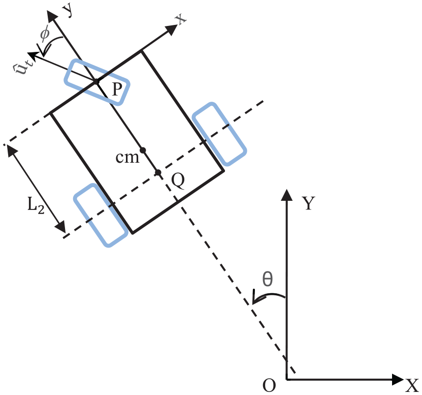
UGV’s position, orientation and geometry on inertial X–Y frame.
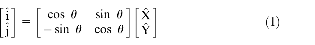
The coordinate transformation from the inertial frame to the body-fixed frame is
The velocity of P can be expressed as

where the unit direction vector

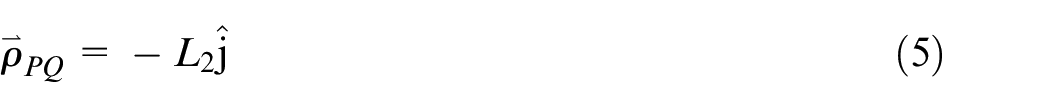
The position vector

where
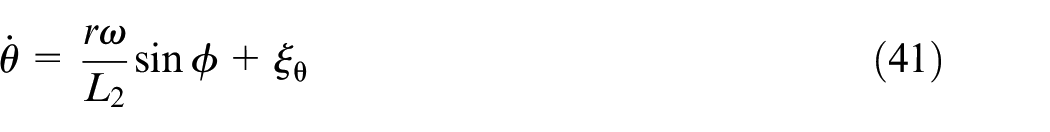
The rate of change of the UGV’s orientation (angular rate of body-fixed frame Pxyz) is expressed by

The velocity of Q(x,y) can be derived as
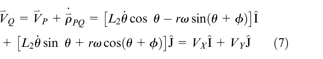
The lateral no-slip condition for the midpoint of the rear wheels can be expressed as

equivalently

The velocity components of equation (7) are substituted into equation (9). After simplification, it yields a useful kinematic equation
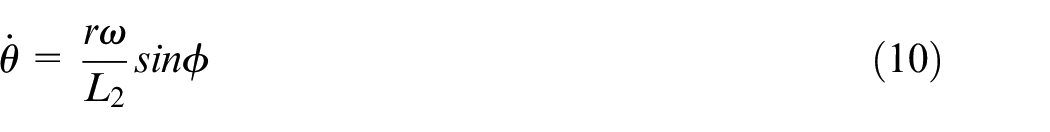
where


Theoretically the trajectory of UGV can be obtained by integration of equations (11) and (12), but in practice it cannot give the accurate position because of integral error from measurement data.
Successive-loop-closure design for lateral control
Since the requirement of cruising speed for the UGV is low, the motion control of the UGV is divided into longitudinal speed control and lateral direction control. The lateral direction control is of vital importance. Two independent DC motors are implemented: one DC motor is used to regulate the UGV cruise speed and the other is used to steer the wheel direction. In speed control design, consider a first-order transfer function model of DC motor from control voltage to angular velocity expressed as the following.
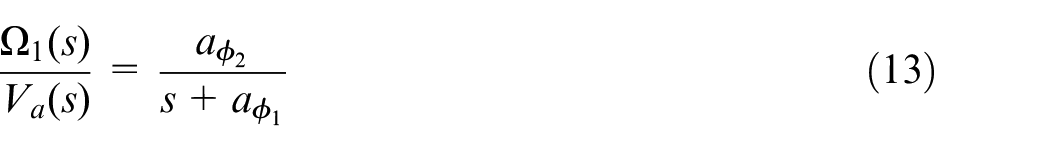
where the coefficients can be determined by DC motor’s specifications and experiment.
The well-known proportional-integral-derivative (PID) controller with a complete structure is designed to fulfill the performance requirement for feedback control design. In control system theory, the transfer function expression of a PID controller from the error to control is
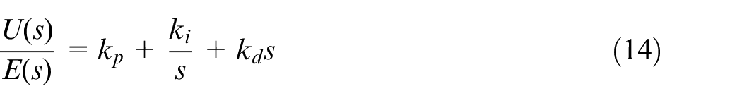
where the proportional gain
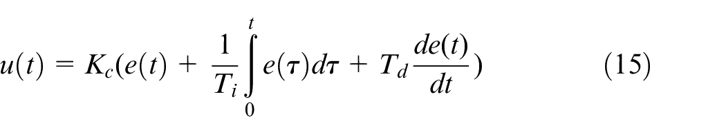
including the proportional parameter
Commonly, the proportional gain
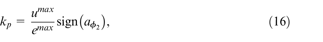
where
Next, for a steady-state error caused by an external disturbance into the system at the summing junction before the system, an integral term is required to effectively eliminate the steady-state error. The combination of the proportional term and integral term becomes a proportional-integral (PI) controller. The integral gain
In position control, consider the open loop the transfer function relating voltage to angular position from equation (13)
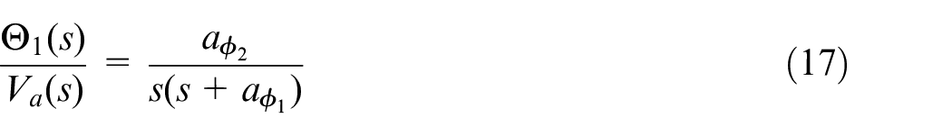
Both the position feedback and the velocity (derivative) feedback are used for the position control. A general second-order transfer function with natural frequency
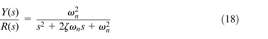
where the natural frequency
Then the derivative gain
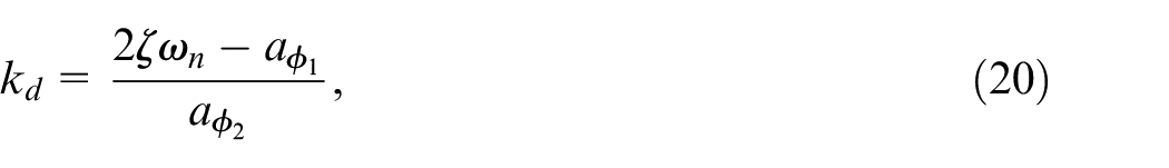
where
The equation (10) is the key kinematics to realize the heading control of UGV by the position control of the steering wheel. Based on the linearization of equation (10), we complete the whole block diagram in Figure 3 for the lateral-directional control of UGV with inner and outer loops. The inner loop is used to control the steering wheel angle
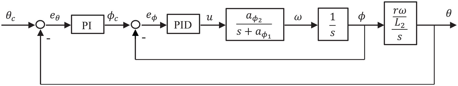
Successive-loop-closure design for UGV lateral control.
The key point of successive-loop-closure approach is bandwidth separation between the inner and outer loops. The performance of the outer loop system is constrained by the inner loop system performance, and usually the performance of the inner loop system is limited by the actuator saturation. To ensure the overall system performance by using successive-loop-closure approach, a sufficient bandwidth separation between the inner and outer loops is essential. Specifically we design the inner loop controller first to achieve the bandwidth as large as possible. Next we design the outer loop controller with a smaller bandwidth by choosing a proper separation factor.
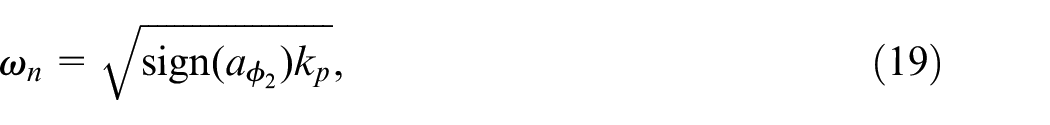
In Figure 3 the PID controller in the inner loop is designed first to control the steering angle with a highest bandwidth, and the inner loop transfer function from
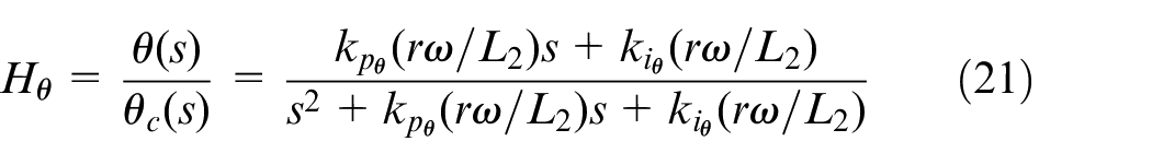
Generalize equation (21) to the following canonical form by introducing the specific parameters
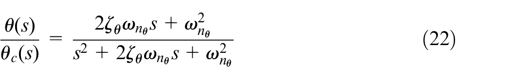
where the natural frequency

The bandwidth separation between the inner and outer loops is defined by

where the separation factor

Now, the design of lateral direction feedback control is completed by using successive-loop-closure approach. Next, we will move on to the guidance design for path-following control.
Path following control and manager
Assume that the desired path can be separated by a sequence of waypoints. Every two adjacent waypoints form a straight-line segment. The straight-line path in planar motion is expressed in the inertial reference frame as follows

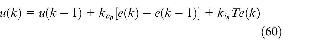
where

where
The critical lateral path error
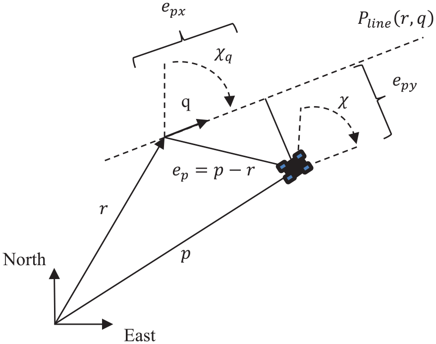
The top-down view of the UGV position and the desired straight-line path.
The rate of change of lateral path error is
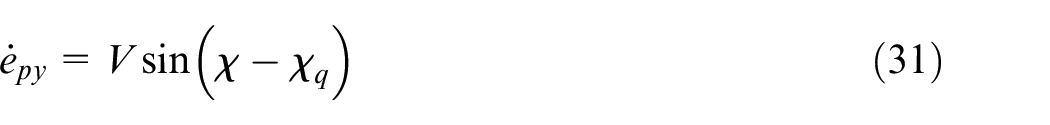
where
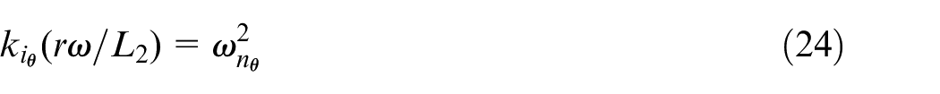
The relevant dynamics of course angle are governed by the transfer function of equation (22). We reformulate it by the following differential equation,
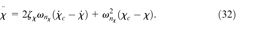
where the subscript is changed to course angle
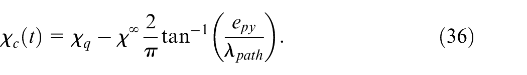
Let
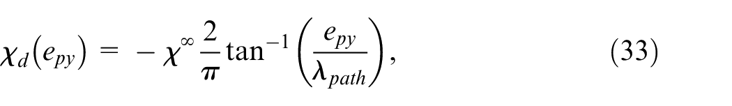
where the course angle at infinity
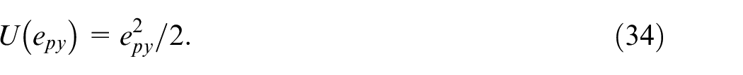
Consider the dynamic system of lateral path error in equation (31). A quadratic form of lateral path error is defined as the Lyapunov function candidate
Its derivative is
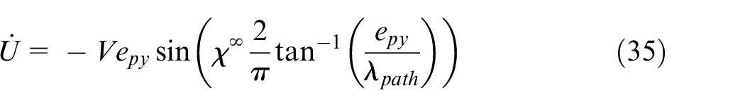
It is clear that
In transitions between successive waypoints, a circle-bound switching criterion is used to manage the UGV target course shift from one straight-line segment to the next. Define a piecewise straight-line-segment path partitioned by a sequence of waypoints

where

where
Kalman filter design
If the sensor system cannot offer the accurate and fast updated position information, the lateral path error cannot be obtained to update the course command from guidance law immediately. Thus the error cannot be effectively reduced in practice by performing the guidance and control law described in the previous sections. In fact the GPS module is a convenient and low-cost device to provide the absolute drift-free position value, but its sampling rate is slow. The 3D orientation sensor—an inertial measurement unit also called attitude and heading reference system (AHRS)—is designed for real-time (high sampling rate) orientation tracking applications. It incorporates three types of sensing elements: three-axis gyroscopes, three-axis accelerometers, and three-axis magnetometers. Those data from the gyroscopes, accelerometers, and magnetometers are processed through the embedded fusion algorithm by the on-board processor and the outputs are the roll, pitch, yaw orientations in body-fixed frame. Since the update rate of position value from GPS is not high enough for guidance control, a dynamic observer that accounts for the underlying system dynamics and merges the data from AHRS and GPS is applied to estimate states optimally. The most commonly used dynamic observer is Kalman filter that is designed by finding an optimal observer gain to minimize covariance of estimation error. In this study, since the system process model and measurement model of UGV are nonlinear, the extended Kalman filter (EKF) is designed to implement the sensor-fusion. A mathematical derivation of EKF is described as follows.
From equations (10) to (12) by adding the random process noise


For measurement, we use the GPS data for north and east position and only the AHRS yaw output. Also by adding the random measurement noise


where the random process noise and measurement noise are assumed to be zero-mean Gaussian processes with covariance Q and R respectively.
Define the state vector as


The continuous-discrete extended Kalman Filter is described by


where L is the Kalman filter gain to be designed; tn is the instant that the measurement is received from sensor,
Define the estimation error as

The objective of Kalman filter design is to find a gain L to minimize the estimation error covariance. After some derivation, the extended Kalman filter is summarized as follows.11,23,24
Between measurements, the propagate of estimation error covariance and the state estimate are given by


where equation (51) is the discrete-time Euler integration. Since the propagation model is nonlinear, the first-order Jacobian of f for A, and the Jacobian of h for C, such as
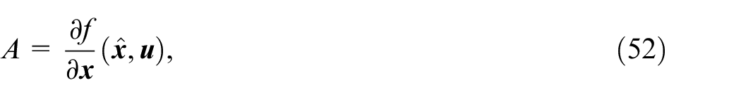
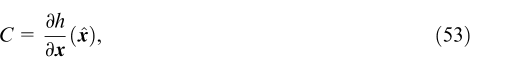
are introduced in the propagation and update process.
When the measurement has been received from sensors, the update equations of Kalman filter gain and estimation error covariance are given by


The implementation of EKF is completed. The state is properly estimated by using equation (48). Note that the EKF design in this study uses only three states and three measurements to estimate the UGV positions in a high update-rate. The small and concise three-state EKF reduces the calculation workloads of the embedded system in performing state estimation. It is an advantage indeed in practical UGV applications.
Results
Guidance and control design
The control voltage of DC motor control voltage is actually implemented by pulse modulation circuit and the duty cycle of pulse-modulation-width (PWM) waveform is used to be the control effort. We carry out the open-loop control experiment to build the linear model of DC motor dynamics in the linear operating range between duty cycle and input voltage. The resulting transfer function from duty cycle to angular speed with a gearhead ratio 1:64 is expressed as
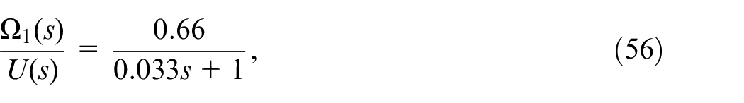
A PI (proportional-integral) controller is designed for speed feedback control by applying the root locus method. We use the LabVIEW PID.vi to implement the PI controller with alternative parameters such as proportional gain

where
The essential of UGV path-following control is the lateral direction control. For steering wheel position control, the DC motor is equipped with a gearhead ratio 1:96 and an additional gear system 14:30 to increase motor torque. Additionally, a heavier inertia loading is existed. Thus, we have the following open-loop transfer function for position feedback control design.
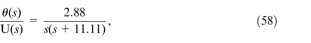
A PID (proportional-integral-differential) controller is designed for the position control of steering wheel. We take account of the constraint of maximum rotation angle of steering wheel and choose an overdamped criterion. The proportional and derivative gains can be obtained from equations (16) and (20). Then the integral gain can be determined by using the root locus method to achieve the desired response. After fine-tuning from field test results, the proportional parameter

where
For the block diagram of UGV lateral control in Figure 3 the inner loop is the angular position control for steering wheel angle
where
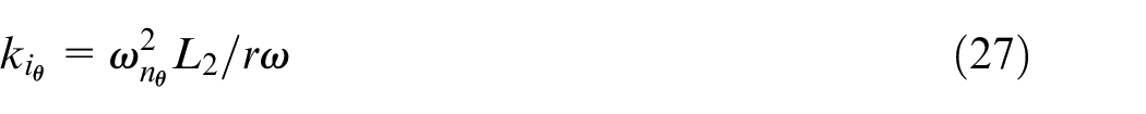
According to equation (19), the natural frequency of the inner loop system is

as the heading loop PI controller gains.
The design parameter
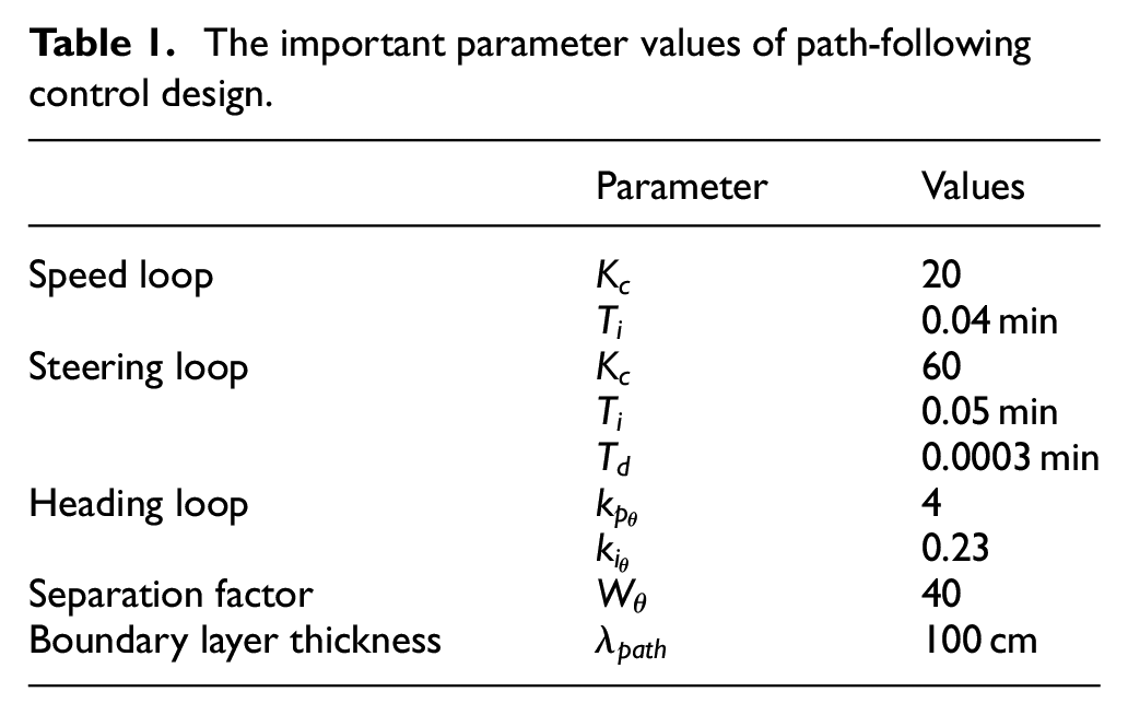
Finally Table 1 summarizes the important parameter values of path-following control design.
The important parameter values of path-following control design.
Remark 1 on the design of PID controller in the inner loop (steering loop)
There are five controller gains—
Remark 2 on the design of PI controller in the outer loop (heading loop)
After the design of PID controller in the inner loop system is obtained, then we design the PI controller in the outer loop system with a lower bandwidth to ensure overall system performance. Since the higher bandwidth of the inner loop system can be computed from equation (19), the lower bandwidth of the outer loop system is determined by equation (25). The separation factor
Remark 3 on the fine-tuning of controller parameters from field test results
It is necessary to make some changes to controller parameters in order to make it work as well as possible in practice. Because the force interactions exist in the boundary (contact point or surface) of system, it is very complicated and time-consuming to build a mathematical model to analyze the effect on the control system. From the engineering point of view after the controllers are designed according to the theory, we have to test the whole system in the field to fine-tune the parameters through the field test results. In our experience the strength of controller designed from theory has to be reduced to ensure a better stability and performance in practice. Specifically, the suggestion is to lower the value of proportional parameter
Remark 4 on the selection of boundary layer thickness on field test
The design parameter
Analysis of field test results
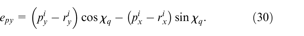
In UGV field test of path-following control we use an onboard GPS module, the u-blox NEO-7 GNSS module, to locate the UGV position and a 3D orientation sensor (AHRS), the InertialLabs OS3D-FG, to measure the course angle. The update rate of GPS is only 1 Hz and the update rate of orientation sensor is 50 Hz. The rate of orientation sensor is high enough for real-time course feedback control, but the slow rate of GPS is not able to provide real-time position data for immediate update on guidance command so that it might yield unsatisfied performance. The problem is solved by using a dynamic observer—the extended Kalman filter (EKF)—to estimate the state efficiently. The EKF fuses the data from GPS module and orientation sensor and produces the estimated UGV position in a smaller time period. Then the corresponding lateral path error is obtained according to equation (30). As a result, the course command from guidance law of equation (36) is updated immediately by the refined lateral path error in a fast rate that is very helpful to improve the performance of path-following control. The field test results of GPS/AHRS with EKF are analyzed in details at first and then are compared with other methods in the following discussion.
The virtual instrument of LabVIEW is applied to give an easy and quick access to accomplish the tasks of design, implementation, and evaluation in field test. The control page and field test results in LabVIEW front panel are shown in Figures 5 and 6. Figure 5 displays the control page in LabVIEW front panel that the parameters values for path-following control including FW PID (front wheel speed control), steering position loop PID control, heading loop PID control, and
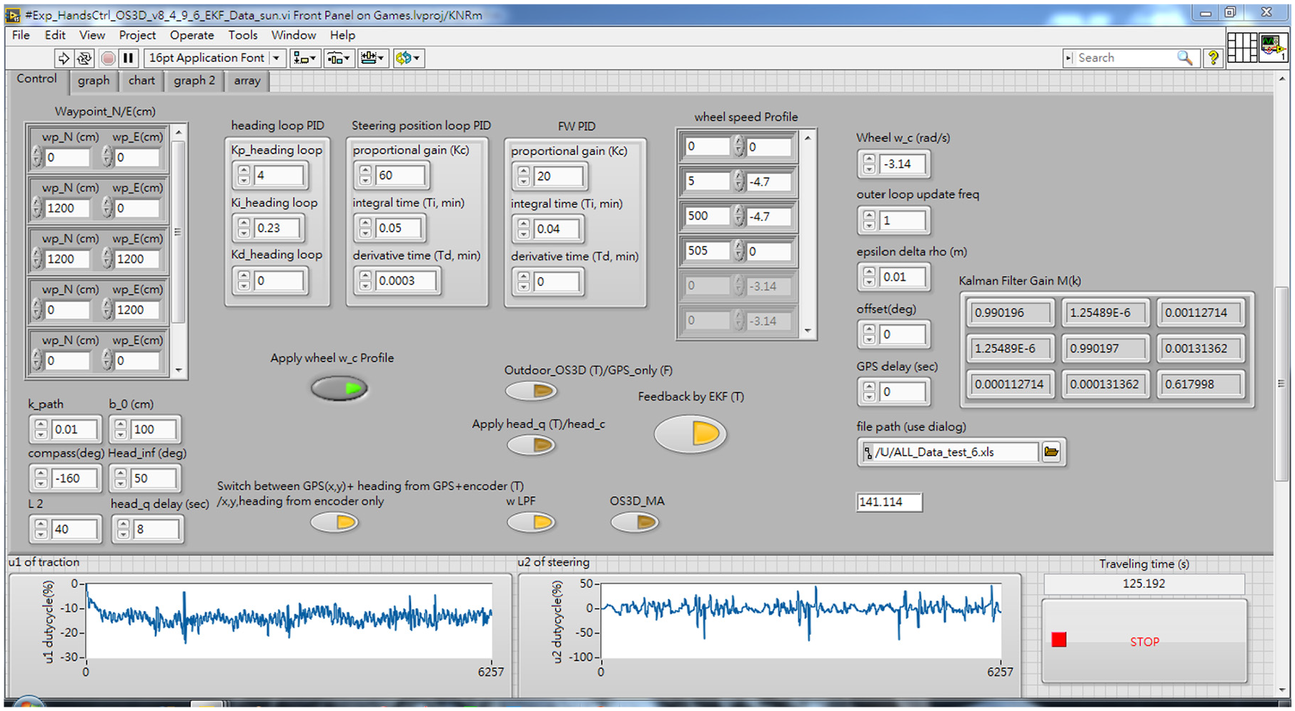
The guidance and control parameters and Kalman filter gains in LabVIEW front panel (control page) at the scene.
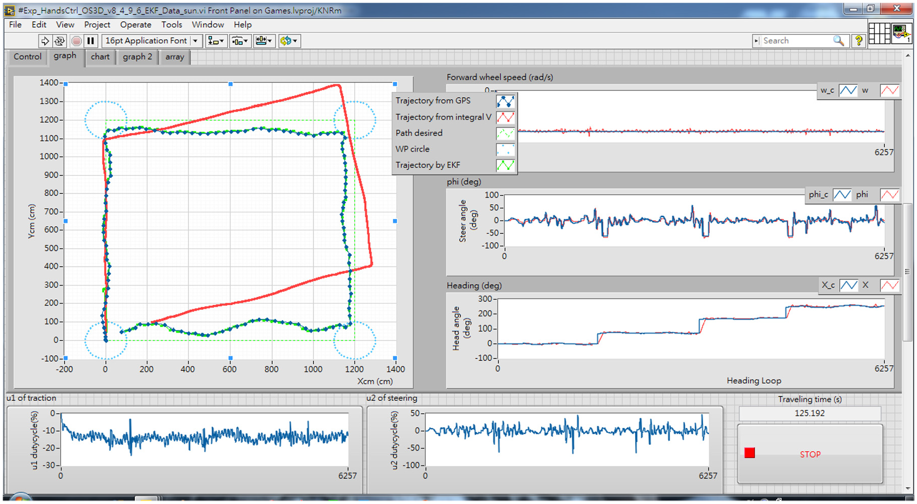
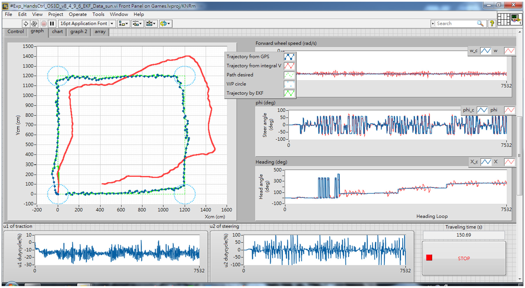
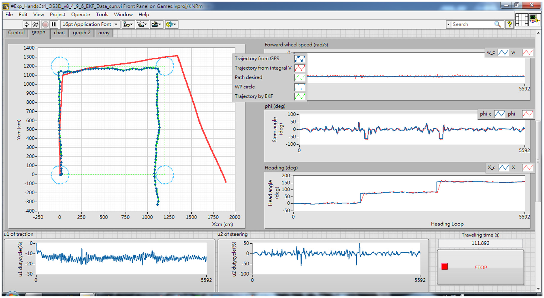
The field test results (GPS/AHRS with EKF) in LabVIEW front panel (graph page) at the scene.
From Figure 6, the graph page in LabVIEW front panel the blue trajectory represents the GPS data of UGV and it clearly demonstrates the proposed GPS/AHRS with EKF design successfully completes path-following mission of a 12-meter square track. Also we notice the red trajectory that it deviates from the blue trajectory—the actual UGV trajectory from GPS—very much. The red trajectory is calculated from the velocity integration of equations (11) and (12), in which the heading angle
Next we examine the lateral control performance of GPS/AHRS with EKF design in detail. The time history of three important variables are presented in Figure 7, in which the steering angle, course angle, and lateral path error are included. A square track with four specified waypoints, where every adjacent waypoint is spaced evenly by 12 m, is used to test the UGV path-following performance. When the UGV enters into the circular boundary of waypoint within 100 cm radius, the new target course
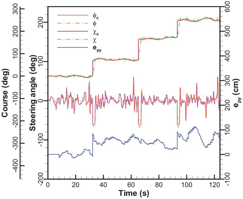
The time response of lateral control in field test by using GPS/AHRS with EKF.
Figures 8 and 9 zoom in the local trajectory to see the difference of position estimates from two EKF designs with different selection of covariance matrix. Both EKF designs are used to complete the path-following successfully. The covariance matrix R of measurement noise is usually set according to the sensor calibration specifications, but the covariance matrix Q of process noise is generally unknown and becomes a design parameter that can be adjusted to obtain a better performance of estimation. In Figure 8 with larger values in
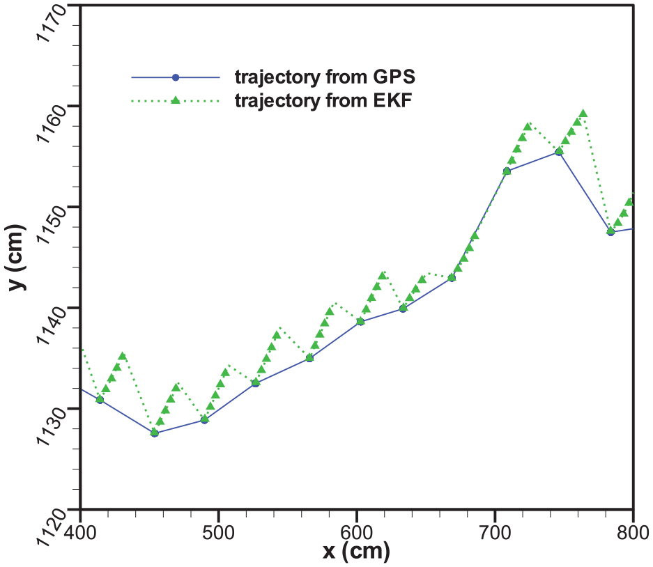
The estimated position of EKF with covariance
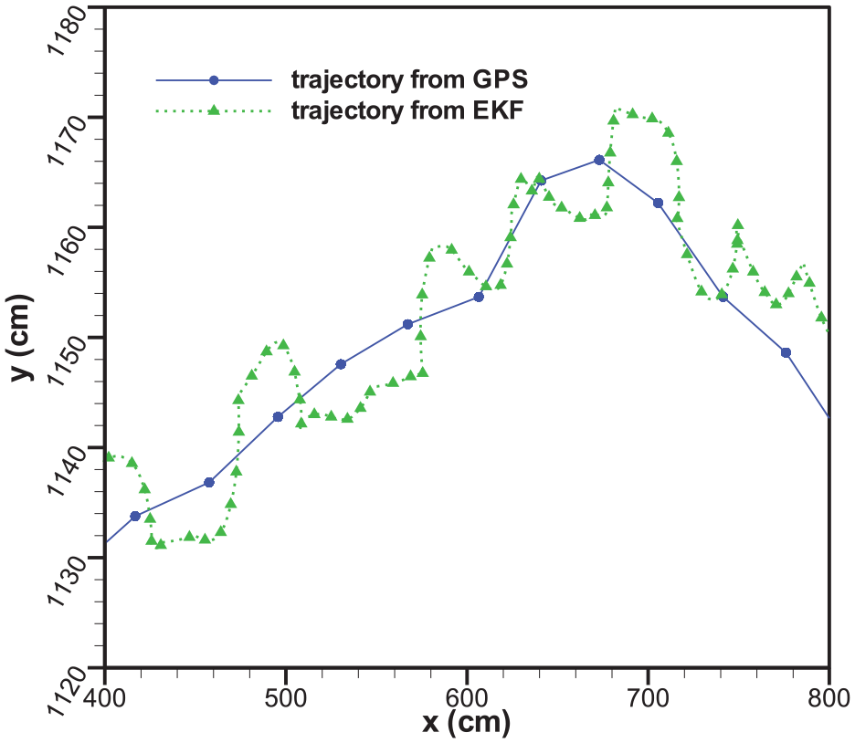
The estimate position of EKF with covariance
We evaluate the proposed GPS/AHRS with EKF method by comparing with two different methods: one is GPS only and the other is GPS/AHRS without EKF. In GPS only without AHRS, the heading information required for the outer feedback loop cannot be obtained from AHRS and instead is obtained by calculating the displacement between two consecutive GPS position data to determine UGV heading. Since the GPS data are updated slowly in every 1 s, it is difficult to achieve real-time orientation tracking control by using course feedback from GPS data only. In addition, GPS data are vulnerable to surrounding obstructions, for example, trees or buildings. The unhealthy position data from GPS usually result in bad performance or even a loss of control. We conduct these field tests and present the results in comparison with the GPS/AHRS with EKF design. Figure 10 presents the field test results in the front panel of LabVIEW at the scene. Although UGV completes the square track path-following, there are intense steering control actions during the field test. Take a close look at Figure 11 the severe correction of steering wheel angle not only reaches the saturation limit frequently but also causes the unacceptable overshoot in course response. The clear difference between the zigzag trajectory from the method of GPS only and the quite smooth trajectory from the method of GPS/AHRS with EKF is shown in Figure 12. The field test results indicate the importance of the diversity of sensors in UGV guidance and control design.
The field test results (GPS only) in the LabVIEW front panel at the scene.
The time response of lateral control in field test by using GPS only.
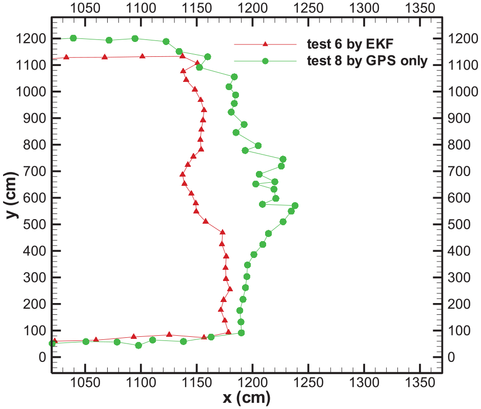
The comparison of UGV trajectories between GPS/AHRS with EKF and GPS only.
After the necessity of multi-sensor is illustrated, next we conduct the field test by using GPS/AHRS without EKF to answer the following question. What if we don’t use EKF to fuse data from GPS and orientation sensor for path-following control? Specifically in GPS/AHRS without EKF the lateral path error is calculated from GPS data and the course command is obtained by equation (36), and in the course feedback control loop the yaw output of AHRS is used. Figure 13 presents the field test results in the front panel of LabVIEW at the scene by using GPS/AHRS without EKF. Although the steering angle is moderate and the heading angle performance is satisfied, clearly the blue trajectory indicates that the UGV missed the waypoint 3.
The field test results (GPS/AHRS without EKF) in LabVIEW front panel at the scene.
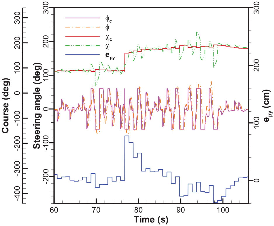
We focus on the third straight-line segment after the UGV passing the second waypoint. To figure out the reason for UGV missing waypoint 3, in the following Figures 14 and 15 we plot the data and carefully compare the field test results of these two different methods: GPS/AHRS with EKF and GPS/AHRS without EKF. Both two methods yield smooth waveforms of steering wheel angle owing to the continuous (high-sampling-rate) course feedback from orientation sensor as shown in Figures 14 and 15. Notice that in Figure 14 the lateral path error shows the piecewise ramp profile by using GPS/AHRS with EKF, but in Figure 15 the lateral path error shows the piecewise step profile by using GPS/AHRS without EKF. The ramp profile results from the action of EKF. The piecewise step profile of the lateral path error results in the same piecewise step profile of course command from equation (36), and so do the piecewise ramp profile. Compare Figure 14 with Figure 15 and we observe that the piecewise step profile of course command is less sensitive to the change of the lateral path error in every period of GPS data update and it might be not able to make an effective feedback control to compensate the disturbance. As a result, UGV using GPS/AHRS without EKF missed the waypoint in field test as shown in Figure 13. By contrast, the resulting piecewise ramp profile of course command by using GPS/AHRS with EKF has the better sensitivity to the lateral path error change and reduces the lateral path error efficiently as shown in Figure 14. Through the detailed comparison of field test results between Figures 14 and 15, we confirm the effectiveness of EKF design in multi-sensor fusion.
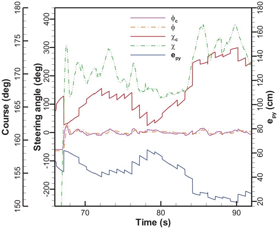
The time response of lateral control in field test by using GPS/AHRS with EKF (zoom in).
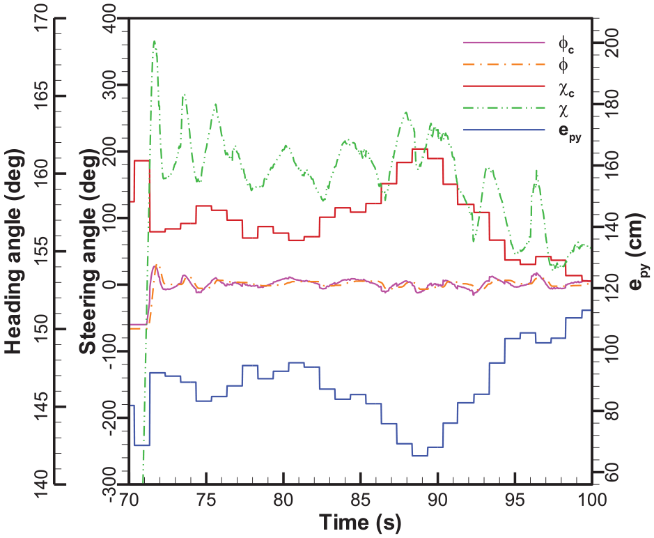
The time response of lateral control in field test by using GPS/AHRS without EKF (zoom in).
Finally, Figure 16 presents the trajectory results obtained by applying GPS/AHRS with EKF, GPS only, and GPS/AHRS independently without EKF in field tests to highlight the superiority of GPS/AHRS with EKF. To sum up, according to the above analysis and comparison, the advantages of GPS/AHRS with EKF is clear for UGV path-following control.
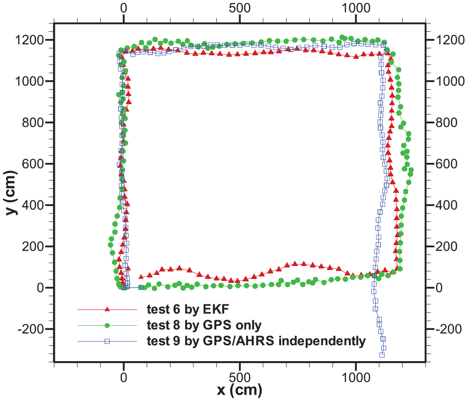
The trajectory comparison of three kinds of design: GPS/AHRS with EKF, GPS only, GPS/AHRS without EKF.
Conclusion
This study presents a complete design of path-following control for a three-wheel car-like-type outdoor UGV. Three major design topics are the lateral-direction control, the vector field-based guidance, and the sensor-fusion. First, the lateral-direction control is developed by using the successive-loop-closure approach, second the vector field-based guidance strategy is designed by applying Lyapunov stability criterion, and third the sensor-fusion of GPS module and orientation sensor is accomplished by using a simple three-state extended Kalman filter. To implement the theoretic design into practice, the fine-tuning of parameters from field test results is necessary. The useful guidelines on the fine-tune of the important design parameters such as bandwidth separation factor in the successive-loop-closure design, the boundary layer width in guidance law, and covariance matrix in EKF are summarized. In addition, the performance of three methods including GPS only, GPS/AHRS without EKF, and GPS/AHRS with EKF are compared in detail to confirm the necessity of multi-sensor fusion and the effectiveness of EKF in UGV path-following control.
Footnotes
Declaration of conflicting interests
The author(s) declared no potential conflicts of interest with respect to the research, authorship, and/or publication of this article.
Funding
The author(s) received no financial support for the research, authorship, and/or publication of this article.